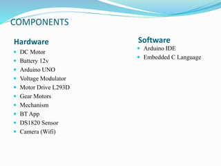
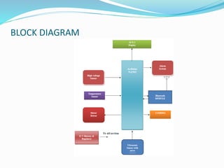
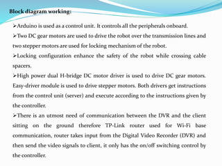
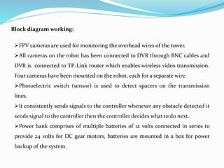
A
PROJECT REPORT
ON
High Voltage Transmission Line Robot
UNDER THE GUIDANCE: SUBMITTED BY:
PROF.SNEHA POOJA(SW18EEE018)
KAVYASHREE(SW18EEE009)
ASHITA(SW18EEE002)
SHIVANI(SW18EEE032)
INTRODUCTION
 Inspection of transmission lines is costly, difficult and a risky job even
for a skilled worker.
 There is a problem of inspecting overhead transmission lines in live
environment.
 In some countries this inspection is carried through aerial inspection
by patrolling helicopter over the transmission lines however this
method is too costly.
 In some regions it can be done manually by the workers but it is also
not the effective way as manual inspection leads to shut down the
power and another most important reason is that there is a human life
at risk while performing this job.
COMPONENTS
 DC Motor
 Battery 12v
 Arduino UNO
 Voltage Modulator
 Motor Drive L293D
 Gear Motors
 Mechanism
 BT App
 DS1820 Sensor
 Camera (Wifi)
 Arduino IDE
 Embedded C Language
Hardware Software
BLOCK DIAGRAM
Block diagram working:
Arduino is used as a control unit. It controls all the peripherals onboard.
Two DC gear motors are used to drive the robot over the transmission lines and
two stepper motors are used for locking mechanism of the robot.
Locking configuration enhance the safety of the robot while crossing cable
spacers.
High power dual H-bridge DC motor driver is used to drive DC gear motors.
Easy-driver module is used to drive stepper motors. Both drivers get instructions
from the control unit (server) and execute according to the instructions given by
the controller.
There is an utmost need of communication between the DVR and the client
sitting on the ground therefore TP-Link router used for Wi-Fi base
communication, router takes input from the Digital Video Recorder (DVR) and
then send the video signals to client, it only has the on/off switching control by
the controller.
Block diagram working:
FPV cameras are used for monitoring the overhead wires of the tower.
All cameras on the robot has been connected to DVR through BNC cables and
DVR is connected to TP-Link router which enables wireless video transmission.
Four cameras have been mounted on the robot, each for a separate wire.
Photoelectric switch (sensor) is used to detect spacers on the transmission
lines.
It consistently sends signals to the controller whenever any obstacle detected it
sends signal to the controller then the controller decides what to do next.
Power bank comprises of multiple batteries of 12 volts connected in series to
provide 24 volts for DC gear motors, batteries are mounted in a box for power
backup of the system.
REAL TIME MODEL
ADVANTAGES
 It assure the safety of human operators.
 Machine body totally on the parallel wires and it would not result in
any harm to the environment and surroundings.
 cost of inspection will get reduce due to use of this robot.
 Moving on the conductor steadily and rapidly.
 Compact construction.
 It saves time and maintenance cost
DISADVANTAGES
 Need to charge battery timely.
 It will monitor the parameters only.
APPLICATIONS
 It is used to detect faults in high voltage transmission
wires
 Tower maintenance
 Line maintenance
 Vegetation control
FUTURE SCOPE
 As the transmission line inspector robot has to pass the obstacles
which is the only drawback thus
 Creates the necessity of installing high end driver motors and well
gripped wheels with accurate balance
 This project can be also modified for inspecting single lines instead of
parallel transmission lines
 To avoid all accident the robot can be thus manipulated and modified
with adding nodes with self
 lifting mechanism with the help of propeller
CONCLUSION
 This project aims at reducing the complexity underlying in inspection
of the overhead high voltage transmission lines by inspecting the main
parameters of the parallel transmission lines by balancing the forward
and reverse moving robot.
 The main aim of the is project is to make an account of the various
parameters timely and then report it to the server or system which is a
computer, it sends the parameters and its values through RF links
through transceivers, as there would be two transceivers, one on the
robot and another on the personal computer which is affixed to a USB
connector which can be inserted into the computer therefore sending
the parameters successfully.
REFERENCE
 [1] Hitachi High-Tech Fine Systems Corporation,’HiBot Corporation
reached the agreement with Hitachi High-Tech Group on the acceleration of
Transmission Line Inspection Business’ January 20, 2014
 [2] Samuel Bouchard, ‘LineScout Robot Climbs on Live Power Lines to
Inspect Them’ 13 August 2010.
 [3] Zheng LI and YI Ruan “Autonomous Inspection Robot for Power
Transmission Line Maintenance While Operating on the Overhead Ground
Wires” Academic press
 [4] Yuvarani C et el. ‘TRANSMISSION LINE INSPECTION ROBOT’.
 [5] Coleman Benson, ‘Drive Motor Sizing Tutorial’ February 1, 2012
 TORKEL DANIELSSON, “Line Inspection Robot”.
THANK YOU

TRANSMISSION LINE ROBOT.pptx

  • 1.
    A PROJECT REPORT ON High VoltageTransmission Line Robot UNDER THE GUIDANCE: SUBMITTED BY: PROF.SNEHA POOJA(SW18EEE018) KAVYASHREE(SW18EEE009) ASHITA(SW18EEE002) SHIVANI(SW18EEE032)
  • 2.
    INTRODUCTION  Inspection oftransmission lines is costly, difficult and a risky job even for a skilled worker.  There is a problem of inspecting overhead transmission lines in live environment.  In some countries this inspection is carried through aerial inspection by patrolling helicopter over the transmission lines however this method is too costly.  In some regions it can be done manually by the workers but it is also not the effective way as manual inspection leads to shut down the power and another most important reason is that there is a human life at risk while performing this job.
  • 3.
    COMPONENTS  DC Motor Battery 12v  Arduino UNO  Voltage Modulator  Motor Drive L293D  Gear Motors  Mechanism  BT App  DS1820 Sensor  Camera (Wifi)  Arduino IDE  Embedded C Language Hardware Software
  • 4.
  • 5.
    Block diagram working: Arduinois used as a control unit. It controls all the peripherals onboard. Two DC gear motors are used to drive the robot over the transmission lines and two stepper motors are used for locking mechanism of the robot. Locking configuration enhance the safety of the robot while crossing cable spacers. High power dual H-bridge DC motor driver is used to drive DC gear motors. Easy-driver module is used to drive stepper motors. Both drivers get instructions from the control unit (server) and execute according to the instructions given by the controller. There is an utmost need of communication between the DVR and the client sitting on the ground therefore TP-Link router used for Wi-Fi base communication, router takes input from the Digital Video Recorder (DVR) and then send the video signals to client, it only has the on/off switching control by the controller.
  • 6.
    Block diagram working: FPVcameras are used for monitoring the overhead wires of the tower. All cameras on the robot has been connected to DVR through BNC cables and DVR is connected to TP-Link router which enables wireless video transmission. Four cameras have been mounted on the robot, each for a separate wire. Photoelectric switch (sensor) is used to detect spacers on the transmission lines. It consistently sends signals to the controller whenever any obstacle detected it sends signal to the controller then the controller decides what to do next. Power bank comprises of multiple batteries of 12 volts connected in series to provide 24 volts for DC gear motors, batteries are mounted in a box for power backup of the system.
  • 7.
  • 8.
    ADVANTAGES  It assurethe safety of human operators.  Machine body totally on the parallel wires and it would not result in any harm to the environment and surroundings.  cost of inspection will get reduce due to use of this robot.  Moving on the conductor steadily and rapidly.  Compact construction.  It saves time and maintenance cost
  • 9.
    DISADVANTAGES  Need tocharge battery timely.  It will monitor the parameters only.
  • 10.
    APPLICATIONS  It isused to detect faults in high voltage transmission wires  Tower maintenance  Line maintenance  Vegetation control
  • 11.
    FUTURE SCOPE  Asthe transmission line inspector robot has to pass the obstacles which is the only drawback thus  Creates the necessity of installing high end driver motors and well gripped wheels with accurate balance  This project can be also modified for inspecting single lines instead of parallel transmission lines  To avoid all accident the robot can be thus manipulated and modified with adding nodes with self  lifting mechanism with the help of propeller
  • 12.
    CONCLUSION  This projectaims at reducing the complexity underlying in inspection of the overhead high voltage transmission lines by inspecting the main parameters of the parallel transmission lines by balancing the forward and reverse moving robot.  The main aim of the is project is to make an account of the various parameters timely and then report it to the server or system which is a computer, it sends the parameters and its values through RF links through transceivers, as there would be two transceivers, one on the robot and another on the personal computer which is affixed to a USB connector which can be inserted into the computer therefore sending the parameters successfully.
  • 13.
    REFERENCE  [1] HitachiHigh-Tech Fine Systems Corporation,’HiBot Corporation reached the agreement with Hitachi High-Tech Group on the acceleration of Transmission Line Inspection Business’ January 20, 2014  [2] Samuel Bouchard, ‘LineScout Robot Climbs on Live Power Lines to Inspect Them’ 13 August 2010.  [3] Zheng LI and YI Ruan “Autonomous Inspection Robot for Power Transmission Line Maintenance While Operating on the Overhead Ground Wires” Academic press  [4] Yuvarani C et el. ‘TRANSMISSION LINE INSPECTION ROBOT’.  [5] Coleman Benson, ‘Drive Motor Sizing Tutorial’ February 1, 2012  TORKEL DANIELSSON, “Line Inspection Robot”.
  • 14.