Download to read offline

![TIP120/TIP121/TIP122 — NPN Epitaxial Darlington Transistor
Typical characteristics
10000
1000
100
VCE = 4V
0.1 1 10
IC[A], COLLECTOR CURRENT
3.5 IC = 250IB
3.0
2.5
2.0
1.5
1.0
0.5
VBE(sat)
VCE(sat)
0.1 1 10
VBE(sat), VCE(sat)[V], SATURATION VOLTAGE
IC[A], COLLECTOR CURRENT
Figure 1. DC current Gain Figure 2. Base-Emitter Saturation Voltage
Collector-Emitter Saturation Voltage
1000
100
10
f=0.1MHz
Cob
Cib
0.1 1 10 100
VCB[V], COLLECTOR-BASE VOLTAGE
VEB[V], EMITTER-BASE VOLTAGE
Figure 3. Output and Input Capacitance
vs. Reverse Voltage
DC
TIP120
TIP121
TIP122
100ms
500ms
1ms
5ms
1 10 100
VCE[V], COLLECTOR-EMITTER VOLTAGE
Figure 4. Safe Operating Area
0 25 50 75 100 125 150 175
TC[oC], CASE TEMPERATURE
Figure 5. Power Derating
hFE, DC CURRENT GAIN
Cob[pF] Cib[pF], CAPACITANCE
10
1
0.1
IC[A], COLLECTOR CURRENT
0.01
80
70
60
50
40
30
20
10
0
PC[W], POWER DISSIPATION
© 2007 Fairchild Semiconductor Corporation www.fairchildsemi.com
TIP120/TIP121/TIP122 Rev. 1.0.0 3](https://image.slidesharecdn.com/tip120-141027005313-conversion-gate01/85/Tip120-datasheet-3-320.jpg)
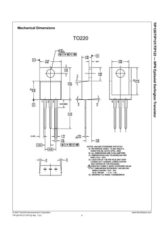

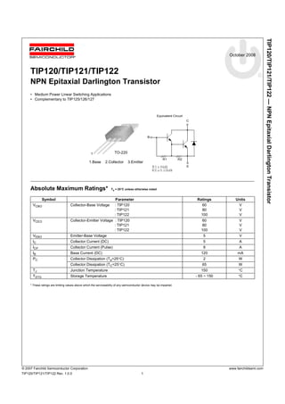
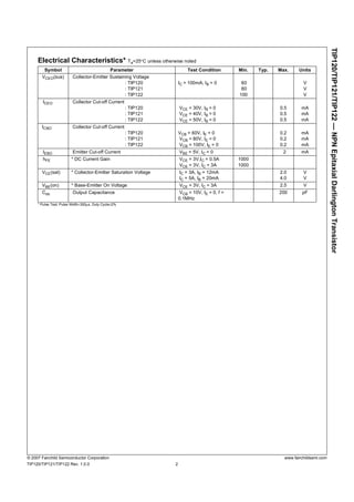
The document describes the TIP120/TIP121/TIP122 NPN Epitaxial Darlington Transistor. It provides specifications for the transistor including maximum ratings, electrical characteristics, typical characteristics, and mechanical dimensions. The transistor is intended for medium power linear and switching applications as a complement to the TIP125/126/127 transistors.


