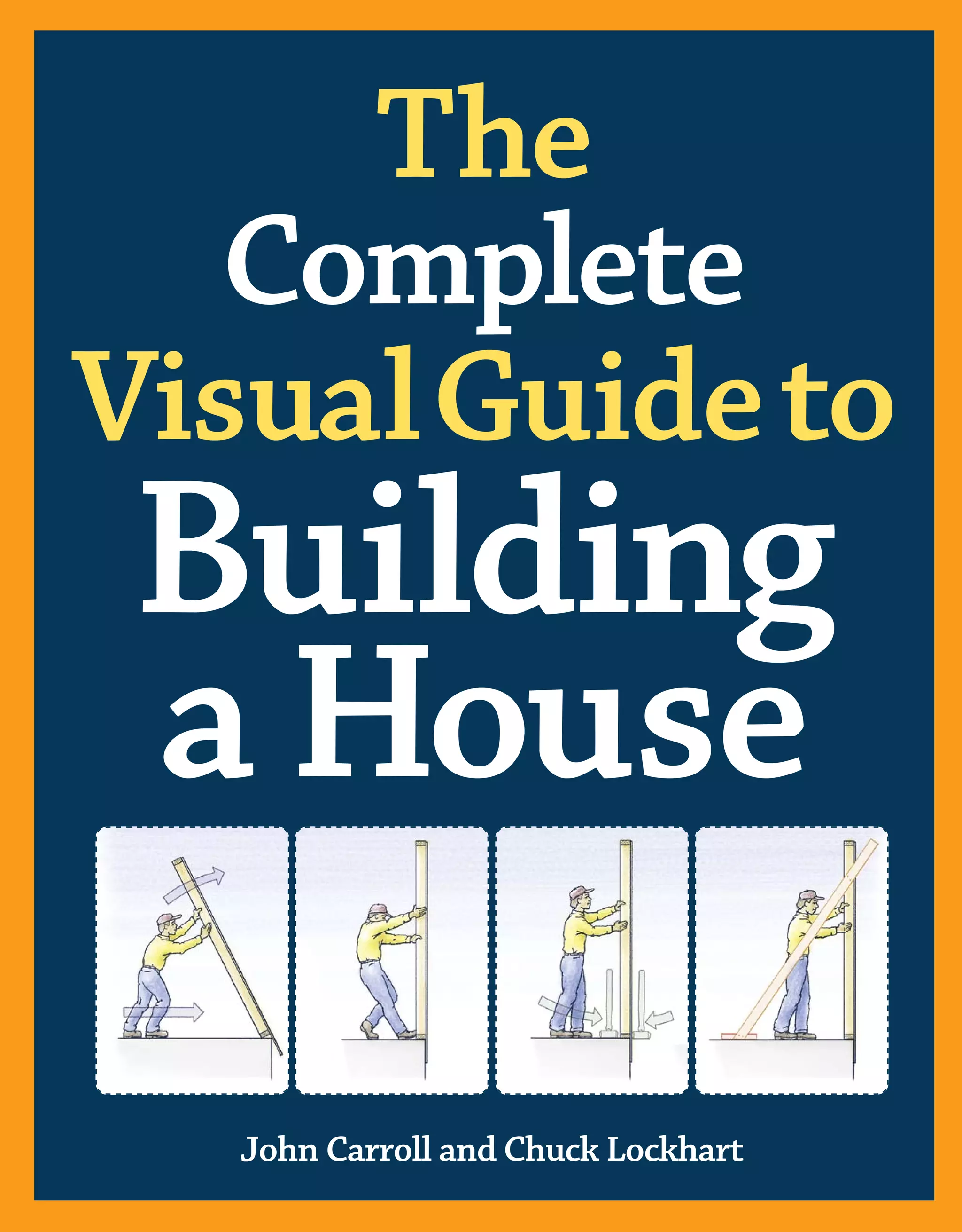
This document provides an introduction to "The Complete Visual Guide to Building a House". It discusses how houses must be built to withstand diverse climates across North America. It also notes that modern homes are expected to maintain comfortable interior environments regardless of outside conditions. The introduction acknowledges the many options in building materials, tools, and systems, and explains that the book will focus primarily on light wood-framed construction since it represents 90% of the housing market. Specific alternative building methods or complex designs are not covered in depth to allow for broader discussion of mainstream construction practices.


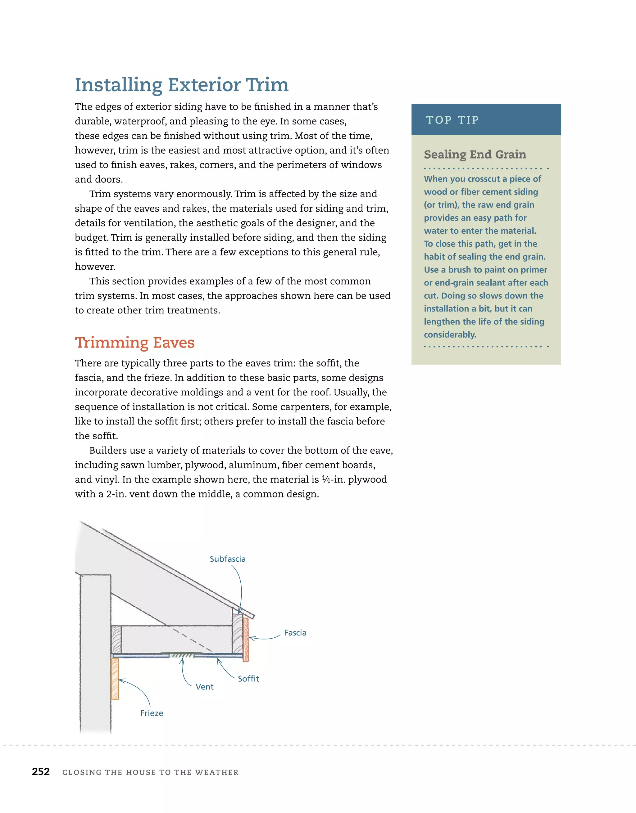

![installing trim and cabinets 401
10
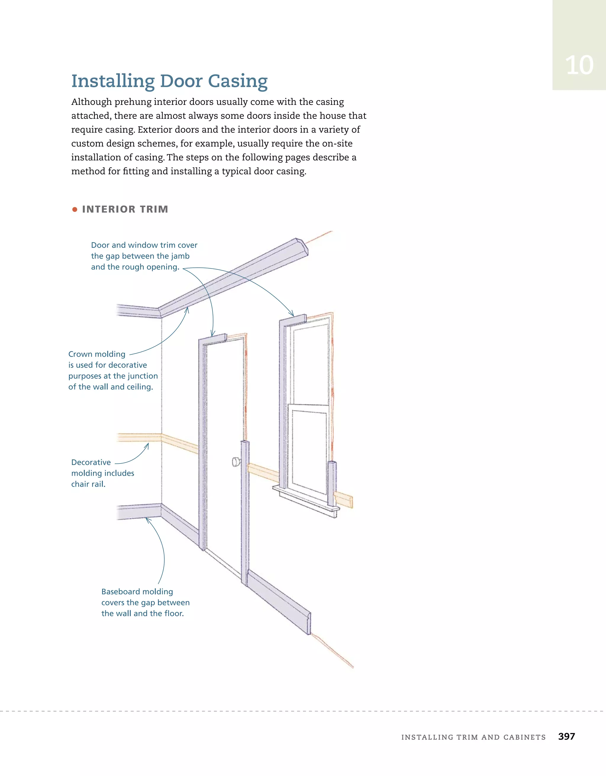
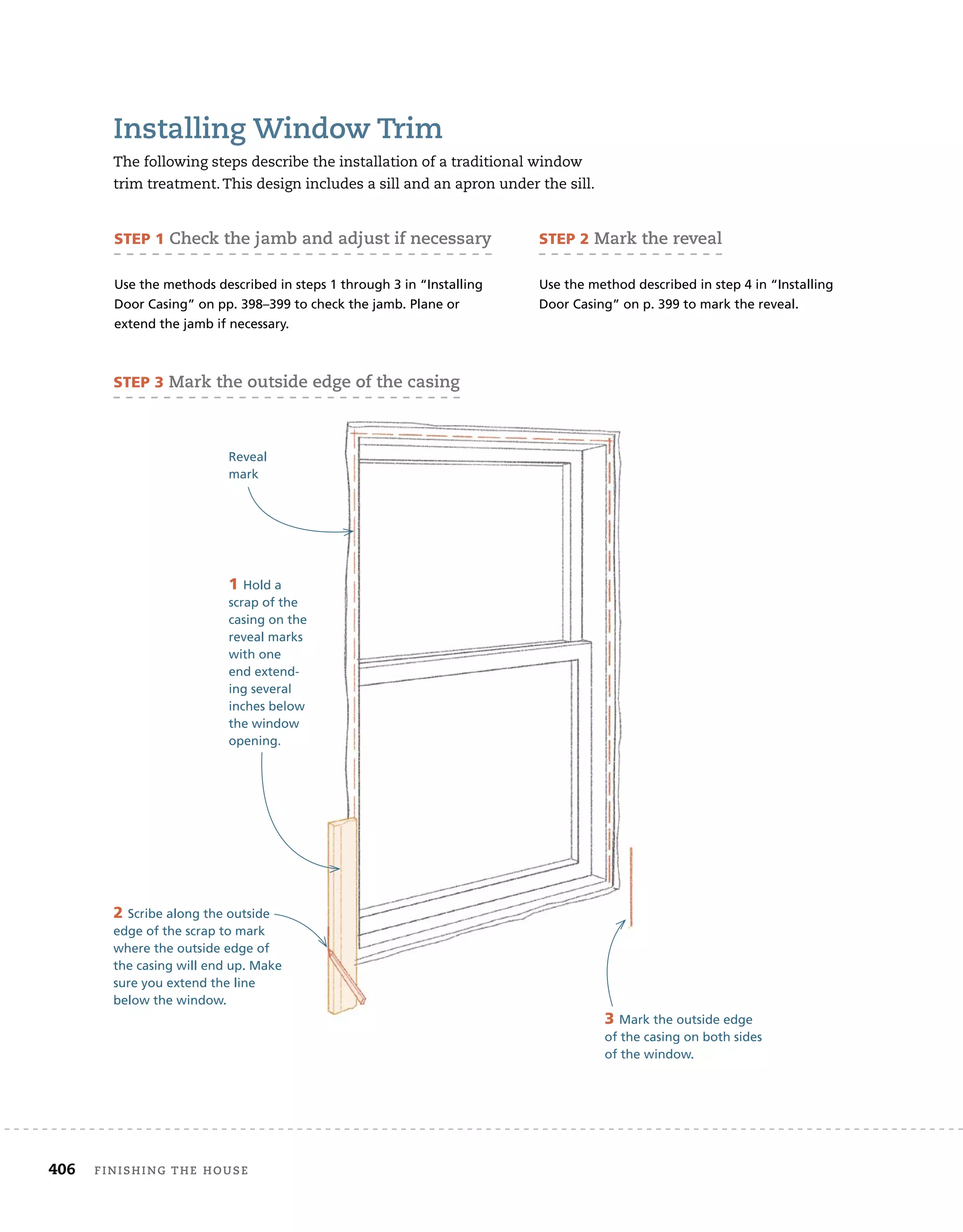
installing Window trim
The following steps describe the installation of a traditional window
trim treatment. This design includes a sill and an apron under the
sill.[Dwgs ch10_18, 19, 20, 21, 22, 23, 24a, 24b, 25,][SB 10-6]
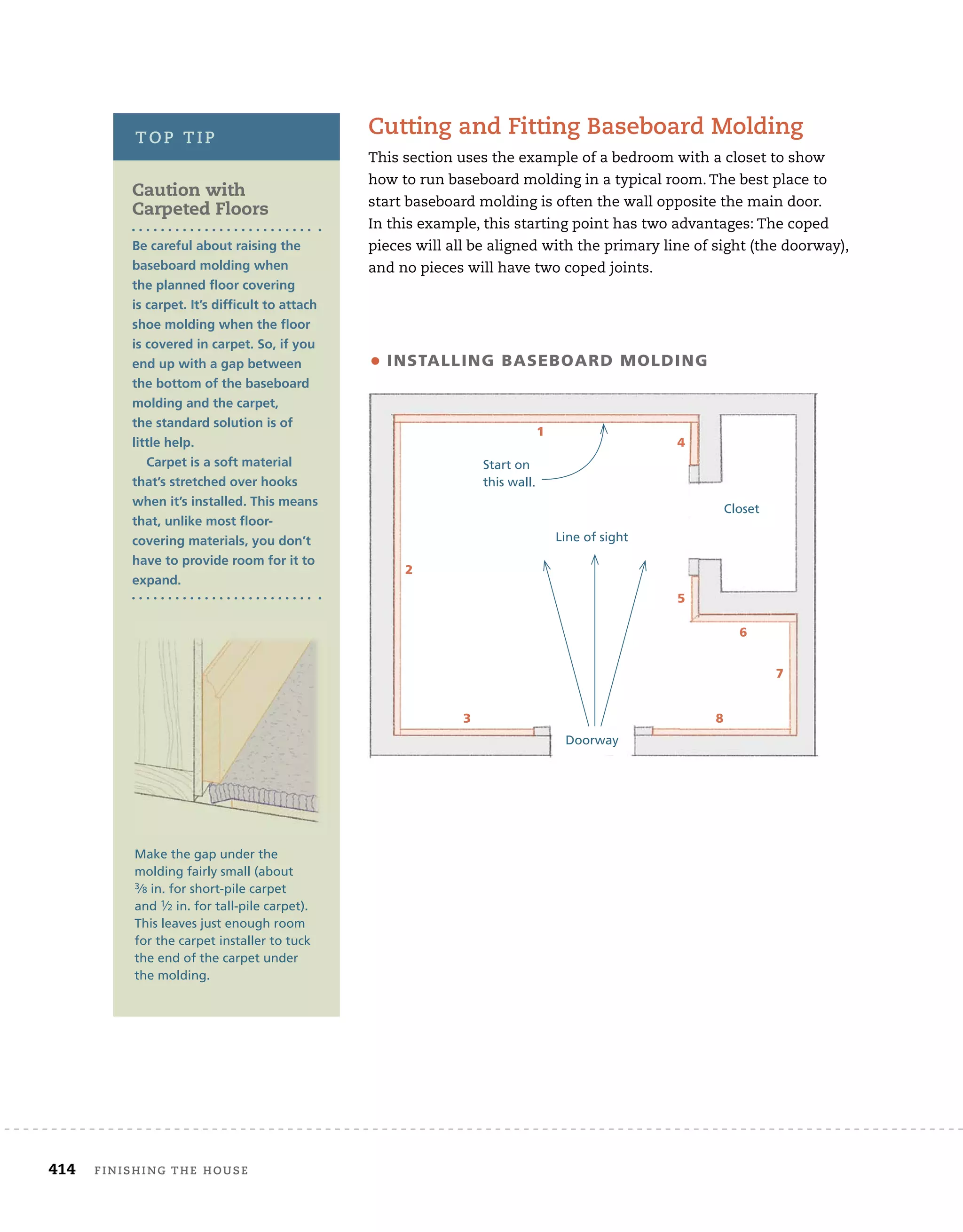
installing baseboard molding
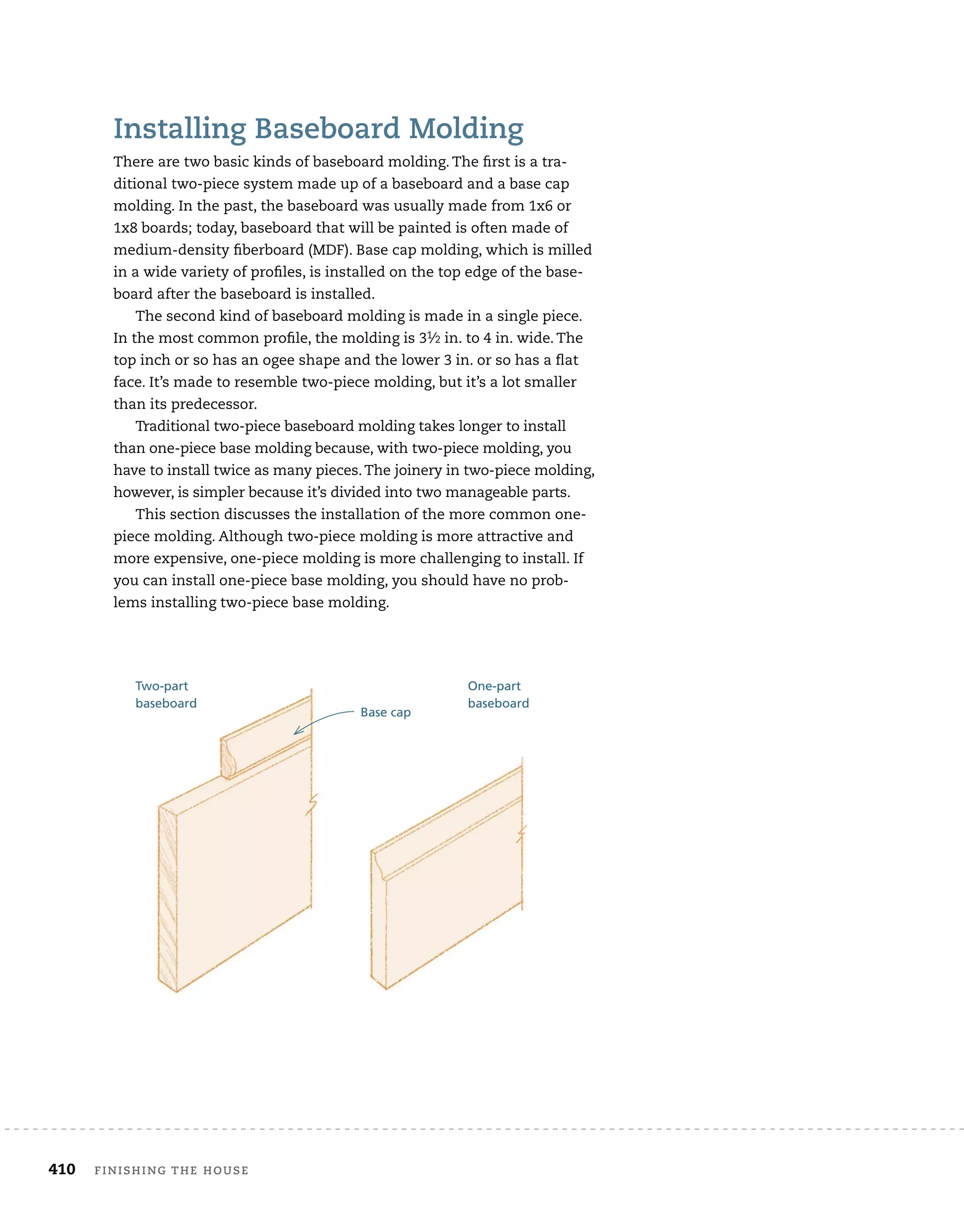
There are two basic kinds of baseboard molding. The fi
rst is a tra-
ditional two-piece system made up of a baseboard and a base cap
molding. In the past, the baseboard was usually made from 1x6 or
1x8 boards; today, baseboard that will be painted is often made of
medium-density fi
berboard (MDF). Base cap molding, which is milled
in a wide variety of profi
les, is installed on the top edge of the base-
board after the baseboard is installed.
The second kind of baseboard molding is made in a single piece.
Other features and considerations
Manufacturers offer a number of other features and
accessories. These include electric brakes, digital
angle readouts, detents and highlighted marks for
common settings, laser lines, dust-collection systems,
work lights, a variety of fence configurations, clamp-
ing systems, and stops. Make sure you consider the
weight of the saw and how much noise it makes. This
information can be found in comparative tool reviews,
tool catalogs, and on Web tool sites. You can also
check the specifications provided online by individual
tool manufacturers.
Sliding compound miter saws
Costing about twice as much as a compound miter saw,
the sliding compound miter saw (SCMS) has a much
larger cutting capacity. On these saws, the motor and
blade assembly is mounted on an arm. By sliding the
assembly along the arm, it’s possible to make very long
yet precise cuts.
Most SCMS are capable of crosscutting boards that
are 12 in. wide. And they’re capable of making compound
miter/bevel cuts at 45°/45° in material that’s 8 in. wide.
Because of its long cutting capacity, the SCMS is also a
great tool for making the compound miter cuts required
for hip and valley roofs.
A 10-in. sliding compound miter saw
can precisely cut just about any base or
crown molding or crosscut shelves
and stair-tread material.
A dual-bevel feature adds to the cost of
the saw, but it’s well worth the money if you
expect to install a lot of crown molding or
build complex roofs.
Dual-bevel feature
By repositioning the motor and handle of their
saws, some manufacturers now offer compound
miter saws and SCMS that can be tilted to the right
or the left.](https://image.slidesharecdn.com/thecompletevisualguidetobuildingahouse-220415183916/75/The-Complete-Visual-Guide-To-Building-A-House-pdf-408-2048.jpg)


![Vibe Coding vs. Spec-Driven Development [Free Meetup]](https://cdn.slidesharecdn.com/ss_thumbnails/vibecodingvsspecdrivendevelopment-251209105622-43f455e7-thumbnail.jpg?width=640&height=640&fit=bounds)

