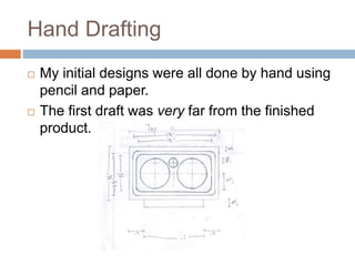
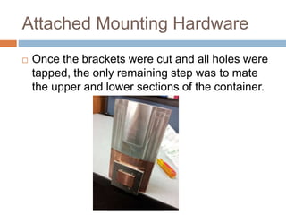
THE CLOVER POT
CUSTOM LIQUID NITROGEN GPU COOLING
CONTAINER
Chance Coats
Personal Introduction
Building Computers
 I assembled my first computer in 2009.
 Incremental upgrades annually since then.
 Saving money lead me to push my
components as far as possible.
 Overclockers.com became my main forum in
early 2009 and I began overclocking.
 After joining the Benchmarking team in 2011,
I have been competing online ever since.
Benchmarking and Extreme
Cooling
 Benchmarking results are tracked on
“HWBot.org”
 Extreme cooling is not required to compete.
 I felt a strong desire to push my hardware
even further past typical limits. Ambient
cooling no longer allowed me to reach my
goals.
 I purchased my first CPU container and used
dry ice.
 After gaining enough experience with dry ice, I
switched to liquid Nitrogen for cooling.
Why use Extreme Cooling ?
 As I pushed my devices further, power
consumption and temperatures quickly got out
of control.
 Sub-ambient cooling methods allow for greater
power dissipation, lower operating voltages,
and most importantly higher clock speeds.
Building my own Container
 CPU containers are extremely useful, but GPU
containers offer increased performance results
for graphics cards when using extreme
cooling.
 Commercially available GPU containers are
expensive and difficult to find in good
condition.
 My advanced drawing class offered me access
to heavy duty machining equipment.
 I enjoy getting my hands dirty and working
through projects.
Clover Pot – Design Process
Hand Drafting
 My initial designs were all done by hand using
pencil and paper.
 The first draft was very far from the finished
product.
CAD Design Process
 My hand sketches went through multiple
revisions as I learned about the machining
process and its limitations.
 After finding a general design, I moved onto
CAD drawing using AutoDesk AutoCAD.
 Once switching to electronic drawing, I was
allowed more freedom to explore base designs
and could visualize the final product in 3D.
Creative Design Process
 Trial, error and testing lead to my final design.
 Early revisions would change as often as
everyday.
The Clover Pot was born
 My final design revision gave me a strong
sense of achievement. I had created a unique
design with strong performance analysis
results.
Intermediate Design Step
 Because school gave me access to a 3D printer,
I was able to take my design process one step
further after finalizing. The design was created
at half scale using extruded ABS plastic.
Design Choices
 A two-piece design was chosen for cost
reasons.
 Copper was used as the base material to offer
superior thermal conductivity near the GPU
core. The increased specific heat of Copper
also offered better load handling properties.
 Aluminum was used for the top of the
container. Lower cost allowed the container to
have a 2-3 fold increase in volume with a slight
increase in cost.
Machining Process
Materials and Tools
 After finalizing my design, I purchased the raw
materials and specialized tools necessary to
machine my design.
Design Specifications and
Precision
 I set lofty goals for myself when machining this
project. Having no prior experience using a 3-
axis mill, I knew the learning curve would be
steep.
 I set a goal of ±0.01’’ tolerances for my general
machining, and ±0.005’’ tolerances for the
mating surfaces between the halves of the
container.
 I met my goal for most of the project, but
unfortunately did not meet these specifications
for all cuts. In the end I was very happy with
The Container Top
 For reasons including material cost, material
hardness and design complexity, I chose to
start with the top half of the container.
 The general process of machining includes
facing and squaring materials before any cuts
are made.
 Raw materials are often close to square, but
not close enough for precise machining.
 All materials were faced to remove major
surface imperfections and squared for precise
machining.
Container Top Machining
 The top half of the container is essentially a
hollow metal tube made to mate with the base
of the container.
Base Machining
 After successfully completing the top half of
the container and meeting nearly 100 percent
of my specifications, I moved on to machine
the copper base.
 This half of the container was considerably
more complex and required finer
measurements as well as nearly three times
as long to machine.
GPU Core Contact Patch
 A key aspect of the base was the section designed to
make contact with the GPU core when in use. This
section required a very smooth finish to provide optimal
heat exchange, but was left rough for the better part of
the machining process.
Internal Base Design
Challenges
 During the design and revision process, I
decided on a relatively complex base design.
This offered superior surface area while still
maintaining a large amount of mass near the
core contact patch.
 Due to time and machine constraints, the
design was simplified during the process.
 Testing after completing the project has shown
the container still offers strong performance
and load handling characteristics.
Internal Machining
 Once the outside of the container was completed, I
began machining the internal surfaces and the surfaces
used for mating with the top half of the container.
Final Internal Machining
 Seen below is the base just after internal machining was
completed.
 Visible in the holes is the cutting oil used throughout the
process to ensure smooth cutting and proper cutting
head cooling.
Completed Internal Surfaces
 After many hours revising the original design
and machining the new features, I had nearly
completed the base of the container.
 The final steps of the base included drilling
and tapping holes used to attach mounting
brackets.
 These brackets were designed for smaller
aluminum plates and cut using a CNC
machine.
Attached Mounting Hardware
 Once the brackets were cut and all holes were
tapped, the only remaining step was to mate
the upper and lower sections of the container.
Clover Pot Results
Benchmark Testing
 After spending approximately 4 months on this
project split between design and machining, I
was itching to test the finished container in the
real world.
 In the world of benchmarking, there are
programs to test nearly all aspects of a
computer. From CPU and memory to GPU and
overall system performance, the list of
benchmarks is incredibly long.
Aquamark3
 Aquamark3 is a GPU specific benchmark
created in 2003 to test the rendering power of
high powered graphics cards.
 Despite its age, world records in this
benchmark are still fought over.
 After hours of pre-testing, I was ready to
freeze one of the graphics cards I had
purchased specifically for benchmarking.
Number 69 in the World
Really Cool Pictures
Hardware Setup Used
 I’ve always been fascinated by pushing
computer hardware to the limits. Results and
pictures of my sessions provide a view into the
insane world of competitive overclocking.
 The hardware used for the previous results
include:
 Intel Core i7 processor and High Performance
DDR3
 Asus Motherboard and Nvidia Graphics Card
Mid Session
Aftermath
Thank you very much for this opportunity to tell
you about myself.
Questions?
Thank you!

Texas Instruments Interview Presentation

  • 1.
    THE CLOVER POT CUSTOMLIQUID NITROGEN GPU COOLING CONTAINER Chance Coats
  • 2.
  • 3.
    Building Computers  Iassembled my first computer in 2009.  Incremental upgrades annually since then.  Saving money lead me to push my components as far as possible.  Overclockers.com became my main forum in early 2009 and I began overclocking.  After joining the Benchmarking team in 2011, I have been competing online ever since.
  • 4.
    Benchmarking and Extreme Cooling Benchmarking results are tracked on “HWBot.org”  Extreme cooling is not required to compete.  I felt a strong desire to push my hardware even further past typical limits. Ambient cooling no longer allowed me to reach my goals.  I purchased my first CPU container and used dry ice.  After gaining enough experience with dry ice, I switched to liquid Nitrogen for cooling.
  • 5.
    Why use ExtremeCooling ?  As I pushed my devices further, power consumption and temperatures quickly got out of control.  Sub-ambient cooling methods allow for greater power dissipation, lower operating voltages, and most importantly higher clock speeds.
  • 6.
    Building my ownContainer  CPU containers are extremely useful, but GPU containers offer increased performance results for graphics cards when using extreme cooling.  Commercially available GPU containers are expensive and difficult to find in good condition.  My advanced drawing class offered me access to heavy duty machining equipment.  I enjoy getting my hands dirty and working through projects.
  • 7.
    Clover Pot –Design Process
  • 8.
    Hand Drafting  Myinitial designs were all done by hand using pencil and paper.  The first draft was very far from the finished product.
  • 9.
    CAD Design Process My hand sketches went through multiple revisions as I learned about the machining process and its limitations.  After finding a general design, I moved onto CAD drawing using AutoDesk AutoCAD.  Once switching to electronic drawing, I was allowed more freedom to explore base designs and could visualize the final product in 3D.
  • 10.
    Creative Design Process Trial, error and testing lead to my final design.  Early revisions would change as often as everyday.
  • 11.
    The Clover Potwas born  My final design revision gave me a strong sense of achievement. I had created a unique design with strong performance analysis results.
  • 12.
    Intermediate Design Step Because school gave me access to a 3D printer, I was able to take my design process one step further after finalizing. The design was created at half scale using extruded ABS plastic.
  • 13.
    Design Choices  Atwo-piece design was chosen for cost reasons.  Copper was used as the base material to offer superior thermal conductivity near the GPU core. The increased specific heat of Copper also offered better load handling properties.  Aluminum was used for the top of the container. Lower cost allowed the container to have a 2-3 fold increase in volume with a slight increase in cost.
  • 14.
  • 15.
    Materials and Tools After finalizing my design, I purchased the raw materials and specialized tools necessary to machine my design.
  • 16.
    Design Specifications and Precision I set lofty goals for myself when machining this project. Having no prior experience using a 3- axis mill, I knew the learning curve would be steep.  I set a goal of ±0.01’’ tolerances for my general machining, and ±0.005’’ tolerances for the mating surfaces between the halves of the container.  I met my goal for most of the project, but unfortunately did not meet these specifications for all cuts. In the end I was very happy with
  • 17.
    The Container Top For reasons including material cost, material hardness and design complexity, I chose to start with the top half of the container.  The general process of machining includes facing and squaring materials before any cuts are made.  Raw materials are often close to square, but not close enough for precise machining.  All materials were faced to remove major surface imperfections and squared for precise machining.
  • 18.
    Container Top Machining The top half of the container is essentially a hollow metal tube made to mate with the base of the container.
  • 19.
    Base Machining  Aftersuccessfully completing the top half of the container and meeting nearly 100 percent of my specifications, I moved on to machine the copper base.  This half of the container was considerably more complex and required finer measurements as well as nearly three times as long to machine.
  • 20.
    GPU Core ContactPatch  A key aspect of the base was the section designed to make contact with the GPU core when in use. This section required a very smooth finish to provide optimal heat exchange, but was left rough for the better part of the machining process.
  • 21.
    Internal Base Design Challenges During the design and revision process, I decided on a relatively complex base design. This offered superior surface area while still maintaining a large amount of mass near the core contact patch.  Due to time and machine constraints, the design was simplified during the process.  Testing after completing the project has shown the container still offers strong performance and load handling characteristics.
  • 22.
    Internal Machining  Oncethe outside of the container was completed, I began machining the internal surfaces and the surfaces used for mating with the top half of the container.
  • 23.
    Final Internal Machining Seen below is the base just after internal machining was completed.  Visible in the holes is the cutting oil used throughout the process to ensure smooth cutting and proper cutting head cooling.
  • 24.
    Completed Internal Surfaces After many hours revising the original design and machining the new features, I had nearly completed the base of the container.  The final steps of the base included drilling and tapping holes used to attach mounting brackets.  These brackets were designed for smaller aluminum plates and cut using a CNC machine.
  • 25.
    Attached Mounting Hardware Once the brackets were cut and all holes were tapped, the only remaining step was to mate the upper and lower sections of the container.
  • 26.
  • 27.
    Benchmark Testing  Afterspending approximately 4 months on this project split between design and machining, I was itching to test the finished container in the real world.  In the world of benchmarking, there are programs to test nearly all aspects of a computer. From CPU and memory to GPU and overall system performance, the list of benchmarks is incredibly long.
  • 28.
    Aquamark3  Aquamark3 isa GPU specific benchmark created in 2003 to test the rendering power of high powered graphics cards.  Despite its age, world records in this benchmark are still fought over.  After hours of pre-testing, I was ready to freeze one of the graphics cards I had purchased specifically for benchmarking.
  • 29.
    Number 69 inthe World
  • 30.
  • 31.
    Hardware Setup Used I’ve always been fascinated by pushing computer hardware to the limits. Results and pictures of my sessions provide a view into the insane world of competitive overclocking.  The hardware used for the previous results include:  Intel Core i7 processor and High Performance DDR3  Asus Motherboard and Nvidia Graphics Card
  • 32.
  • 33.
  • 34.
    Thank you verymuch for this opportunity to tell you about myself. Questions? Thank you!