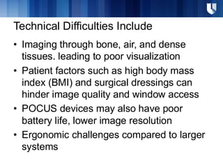
Technical Difficulties Include
•Imaging through bone, air, and dense
tissues. leading to poor visualization
• Patient factors such as high body mass
index (BMI) and surgical dressings can
hinder image quality and window access
• POCUS devices may also have poor
battery life, lower image resolution
• Ergonomic challenges compared to larger
systems
4.
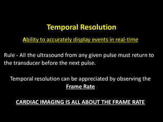
Temporal Resolution
Ability toaccurately display events in real-time
Rule - All the ultrasound from any given pulse must return to
the transducer before the next pulse.
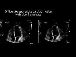
Temporal resolution can be appreciated by observing the
Frame Rate
CARDIAC IMAGING IS ALL ABOUT THE FRAME RATE
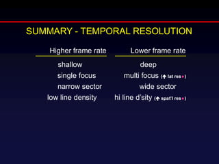
Higher frame rateLower frame rate
shallow deep
single focus multi focus ( lat res)
narrow sector wide sector
low line density hi line d’sity ( spat’l res)
SUMMARY - TEMPORAL RESOLUTION
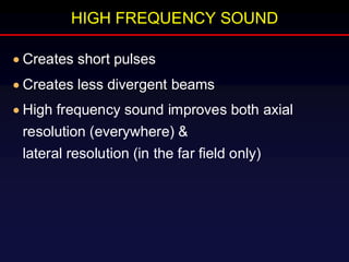
HIGH FREQUENCY SOUND
•Creates short pulses
• Creates less divergent beams
• High frequency sound improves both axial
resolution (everywhere) &
lateral resolution (in the far field only)
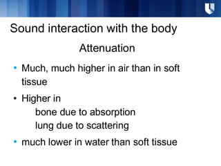
Attenuation
• Much, muchhigher in air than in soft
tissue
• Higher in
bone due to absorption
lung due to scattering
• much lower in water than soft tissue
Sound interaction with the body
11.
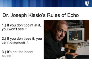
Dr. Joseph Kisslo’sRules of Echo
1.) If you don’t point at it,
you won’t see it
2.) If you don’t see it, you
can’t diagnosis it
3.) It’s not the heart
stupid !
12.
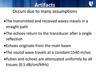
Artifacts
Occurs due tomany assumptions
•The transmitted and received waves travels in a
straight path
•The echoes return to the transducer after a single
reflection
•Echoes originate from the main beam
•The sound wave travels at a constant 1540 m/sec
•Pulses and echoes are attenuated uniformly by all
tissues (0.5 dB/cm/MHz)
13.
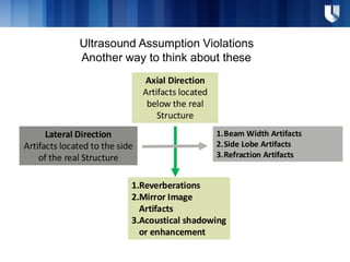
Ultrasound Assumption Violations
Anotherway to think about these
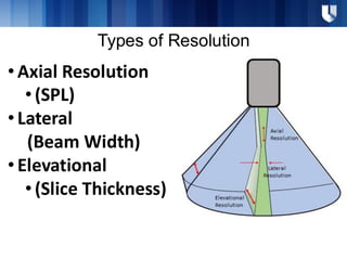
Axial Direction
Artifacts located
below the real
Structure
Lateral Direction
Artifacts located to the side
of the real Structure
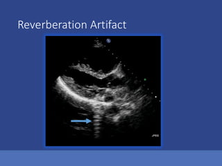
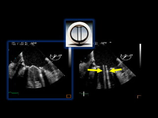
1.Reverberations
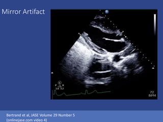
2.Mirror Image
Artifacts
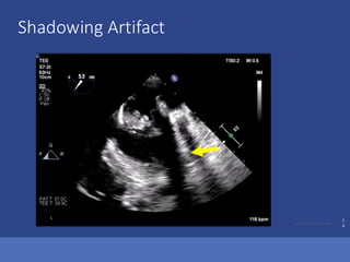
3.Acoustical shadowing
or enhancement
1.Beam Width Artifacts
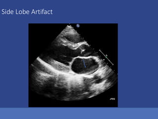
2.Side Lobe Artifacts
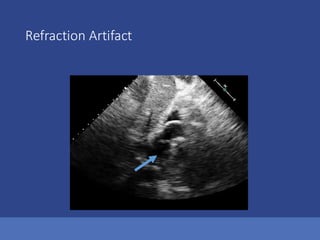
3.Refraction Artifacts
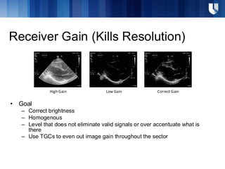
Receiver Gain (KillsResolution)
• Goal
– Correct brightness
– Homogenous
– Level that does not eliminate valid signals or over accentuate what is
there
– Use TGCs to even out image gain throughout the sector
High Gain Low Gain Correct Gain


![CASE_PRESENTATION_ON_subdural_hematoma(SDH)[1 FINAL PPT]-1.pptx](https://cdn.slidesharecdn.com/ss_thumbnails/casepresentationonsubduralhematomasdh1finalppt-1-260129172522-d405d375-thumbnail.jpg?width=640&height=640&fit=bounds)


