A synchronous motor is an AC motor in which the rotor rotates at the same speed as the stator's magnetic field (synchronous speed). It differs from an induction motor, where the rotor lags slightly behind the stator field.
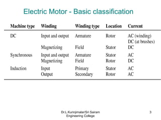
Electric Motor -Basic classification
3
Dr.L.Kurinjimalar/Sri Sairam
Engineering College
4.
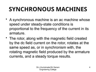
SYNCHRONOUS MACHINES
• Asynchronous machine is an ac machine whose
speed under steady-state conditions is
proportional to the frequency of the current in its
armature.
• The rotor, along with the magnetic field created
by the dc field current on the rotor, rotates at the
same speed as, or in synchronism with, the
rotating magnetic field produced by the armature
currents, and a steady torque results.
4
Dr.L.Kurinjimalar/Sri Sairam
Engineering College
5.
Generation of electricalenergy by utility companies
is done almost exclusively with synchronous
machines.
Assuming a constant frequency source, the speed
of a synchronous motor does not vary with load.
The stator windings of a synchronous machine are
basically the same as those of an induction
machine.
5
Dr.L.Kurinjimalar/Sri Sairam
Engineering College
6.
• Synchronous machines:
•Armature winding: on the stator, alternating
current.
• Field winding: on the rotor, dc power supplied by
the excitation system.
– Cylindrical rotor: for two- and four-pole turbine
generators.
– Salient-pole rotor: for multipolar, slow-speed,
hydroelectric generators and for most synchronous
motors.
• Acting as a voltage source:
– Frequency determined by the speed of its mechanical
drive (or prime mover).
– The amplitude of the generated voltage is proportional
to the frequency and the field current
6
Dr.L.Kurinjimalar/Sri Sairam
Engineering College
7.
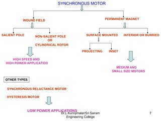
SYNCHRONOUS MOTOR
WOUND FIELDPERMANENT MAGNET
SYNCHRONOUS RELUCTANCE MOTOR
HYSTERESIS MOTOR
SALIENT POLE NON-SALIENT POLE
OR
CYLINDRICAL ROTOR
HIGH SPEED AND
HIGH POWER APPLICATIOS
SURFACE MOUNTED INTERIOR OR BURRIED
PROJECTING INSET
MEDIUM AND
SMALL SIZE MOTORS
OTHER TYPES
LOW POWER APPLICATIONS
7
Dr.L.Kurinjimalar/Sri Sairam
Engineering College
8.
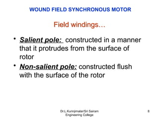
Field windings…
• Salientpole: constructed in a manner
that it protrudes from the surface of
rotor
• Non-salient pole: constructed flush
with the surface of the rotor
WOUND FIELD SYNCHRONOUS MOTOR
8
Dr.L.Kurinjimalar/Sri Sairam
Engineering College
9.
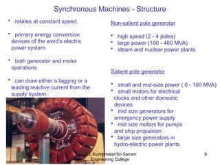
Synchronous Machines -Structure
Non-salient pole generator
• high speed (2 - 4 poles)
• large power (100 - 400 MVA)
• steam and nuclear power plants
Salient pole generator
• small and mid-size power ( 0 - 100 MVA)
• small motors for electrical
clocks and other domestic
devices
• mid size generators for
emergency power supply
• mid size motors for pumps
and ship propulsion
• large size generators in
hydro-electric power plants
• rotates at constant speed.
• primary energy conversion
devices of the word’s electric
power system.
• both generator and motor
operations
• can draw either a lagging or a
leading reactive current from the
supply system.
9
Dr.L.Kurinjimalar/Sri Sairam
Engineering College
10.
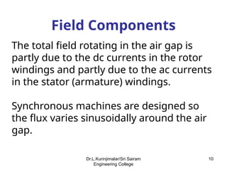
Field Components
The totalfield rotating in the air gap is
partly due to the dc currents in the rotor
windings and partly due to the ac currents
in the stator (armature) windings.
Synchronous machines are designed so
the flux varies sinusoidally around the air
gap.
10
Dr.L.Kurinjimalar/Sri Sairam
Engineering College
11.
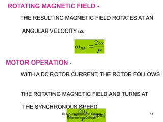
ROTATING MAGNETIC FIELD-
THE RESULTING MAGNETIC FIELD ROTATES AT AN
ANGULAR VELOCITY ω.
MOTOR OPERATION -
WITH A DC ROTOR CURRENT, THE ROTOR FOLLOWS
THE ROTATING MAGNETIC FIELD AND TURNS AT
THE SYNCHRONOUS SPEED
P
M
2
)
rpm
(
120
P
f
nS 11
Dr.L.Kurinjimalar/Sri Sairam
Engineering College
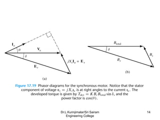
12.
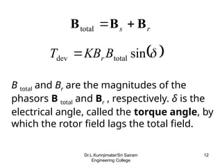
r
s B
B
B
total
sin
total
dev B
KB
T r
B total and Br are the magnitudes of the
phasors B total and Br , respectively. δ is the
electrical angle, called the torque angle, by
which the rotor field lags the total field.
12
Dr.L.Kurinjimalar/Sri Sairam
Engineering College
13.
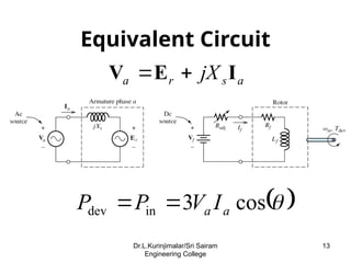
Equivalent Circuit
a
s
r
a jXI
E
V
cos
3
in
dev a
a I
V
P
P
13
Dr.L.Kurinjimalar/Sri Sairam
Engineering College
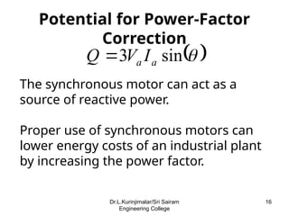
Potential for Power-Factor
Correction
sin
3 a
a I
V
Q
The synchronous motor can act as a
source of reactive power.
Proper use of synchronous motors can
lower energy costs of an industrial plant
by increasing the power factor.
16
Dr.L.Kurinjimalar/Sri Sairam
Engineering College
17.
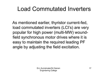
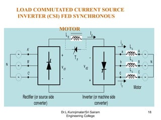
Load Commutated Inverters
Asmentioned earlier, thyristor current-fed,
load commutated inverters (LCI’s) are very
popular for high power (multi-MW) wound-
field synchronous motor drives where it is
easy to maintain the required leading PF
angle by adjusting the field excitation.
17
Dr.L.Kurinjimalar/Sri Sairam
Engineering College
18.
~ ~
~
~ ~
~
A
B
C
a
b
c
A'
B'
C'
N
N
Lc
Lc
Lc
Id
Rectifier(or source side
converter)
Inverter (or machine side
converter)
+
-
-
+
vd1
vd2
Ld
TF
ic
ia
Motor
LOAD COMMUTATED CURRENT SOURCE
INVERTER (CSI) FED SYNCHRONOUS
MOTOR
18
Dr.L.Kurinjimalar/Sri Sairam
Engineering College
19.
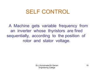
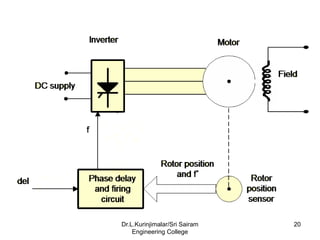
SELF CONTROL
A Machinegets variable frequency from
an inverter whose thyristors are fired
sequentially, according to the position of
rotor and stator voltage.
19
Dr.L.Kurinjimalar/Sri Sairam
Engineering College
DISADVANTAGES
• SPARKING
• MAINTENANCEAND RELIABILITY
PROBLEMS
• EMI PROBLEM
• LIMITATIONS IN SPEED AND POWER
RATING
• DIFFICULTY IN OPERATING IN
CORROSIVE AND EXPLOSIVE
ENVIRONMENT
22
Dr.L.Kurinjimalar/Sri Sairam
Engineering College
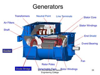
Generators
Exciter
D-end Bearing
Diode Bridge
EndShield
Rotor Poles
Transformers Line Terminals
Shaft
Stator Core
Fan
Stator Windings
Neutral Point
Detachable Feet
Air Filters
Rotor Windings 24
Dr.L.Kurinjimalar/Sri Sairam
Engineering College
25.
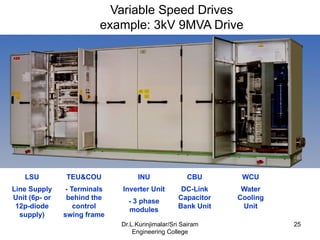
Variable Speed Drives
example:3kV 9MVA Drive
LSU
Line Supply
Unit (6p- or
12p-diode
supply)
TEU&COU
- Terminals
behind the
control
swing frame
INU
Inverter Unit
- 3 phase
modules
CBU
DC-Link
Capacitor
Bank Unit
WCU
Water
Cooling
Unit
25
Dr.L.Kurinjimalar/Sri Sairam
Engineering College
26.
APPLICATIONS
• FIBER SPINNINGMILLS
• ROLLING MILLS CEMENT MILLS
• SHIP PROPULSION
• CEMENT MILLS
• ELECTRIC VEHICLES
• SERVO AND ROBOTIC DEVICES
• MAGLEV-LINEAR SYNCHRONOUS MOTOR
PROPULSION
• STARTERS/GENERATORS FOR AIRCRAFT ENGINES
26
Dr.L.Kurinjimalar/Sri Sairam
Engineering College
27.
REFERENCES
• BIMAL.K.BOSE,”MODERN POWERELECTRONICSAND AC
DRVES”,PEARSON EDUCATION ASIA 2002.
• VEDAM SUBRAMANIAM,”ELECTRIC DRIVES- CONCEPTS AND
APPLICATIONS”,TATA MC GRAW HILL,1994
• HANDBOOK OF AUTOMATIVE POWER ELECTRONICS AND
DRIVES BY
ALI EMADI
• http//:uenics.evansville.edu
• www.toolingu.com
• www.ece.vill.edu
• www.uwindsor.ca
• www.basler.com
27
Dr.L.Kurinjimalar/Sri Sairam
Engineering College