Häny grouting equipment - General informationMladen Zahariev
The INJECTO-COMPACT (IC) grout plants consist of an HCM mixer, an HRW agitator and a ZMP grout pump. All components are functionally arranged on a common base with a central lifting point. The use of the INJECTO-COMPACT grout plants reduce considerably the installation time on site and minimises operating
personnel. The INJECTO-COMPACT (IC) 310/325 are suitable for grouting tie- back anchors, rock bolts, soil nails, tension cables as well as for tube-à-manchette and rock grouting. In microtunnelling, these compact plants are used to mix and inject bentonite suspensions.
JCB 8032Z MINI EXCAVATOR Service Repair Manual SN899000 Onwardsjknjekmds
This is the Highly Detailed factory service repair manual for theJCB 8032Z MINI EXCAVATOR, this Service Manual has detailed illustrations as well as step by step instructions,It is 100 percents complete and intact. they are specifically written for the do-it-yourself-er as well as the experienced mechanic.JCB 8032Z MINI EXCAVATOR Service Repair Workshop Manual provides step-by-step instructions based on the complete dis-assembly of the machine. It is this level of detail, along with hundreds of photos and illustrations, that guide the reader through each service and repair procedure. Complete download comes in pdf format which can work under all PC based windows operating system and Mac also, All pages are printable. Using this repair manual is an inexpensive way to keep your vehicle working properly.
Service Repair Manual Covers:
General Information
Care and Safety
Routine Maintenance
Optional Equipment
Body and Framework
Electrics
Controls
Hydraulics
Transmission
Track and Running Gear
Engine
File Format: PDF
Compatible: All Versions of Windows & Mac
Language: English
Requirements: Adobe PDF Reader
NO waiting, Buy from responsible seller and get INSTANT DOWNLOAD, Without wasting your hard-owned money on uncertainty or surprise! All pages are is great to haveJCB 8032Z MINI EXCAVATOR Service Repair Workshop Manual.
Looking for some other Service Repair Manual,please check:
https://www.aservicemanualpdf.com/
Thanks for visiting!
8
Jys casting for metso hp200 cone crusher partsTomas Chien
We design and metso hp200 cone crusher parts castings for mining, crushing, grinding, shredding, and custom applications for industrial clients worldwide.
12 tic insert liners double the service lifeFernando Zhang
Why is TIC Liner more wearable?
A. The structure and properties of the matrix of the parts have changed. We have increased the content of Mn, Mo, and rare earth.
Therefore, the metallographic grain size of Hadfield steel is refined and the strength is enhanced.
B. The hardness of TIC Insert exceeds HRC60, and the hardness is about 3 times that of Hadfield steel!
The arrangement of Fine Chamber is almost the same as that of rough Chamber. According to the structure of the casting, Feed Size, make some small adjustments, there is no major change.
C. TIC Insert is a mesh-like structure, which is divided into points on the wear part, so as to achieve the purpose of improving the wear resistance of the part as a whole.
For TIC design, our engineers once again improved the design based on the wear curve of the parts you provided.
The size of the ore entering the Fine Chamber is very small, so we reduced the diameter and arrangement spacing of the TIC in order to obtain the best wear effect.
I share these ideas with you to let you fully understand the in-depth research we have done in this project.
Every new project is full of challenges and unknowns, but we are willing to challenge some interesting & valuable projects together with new customer.
How to solve the problem of excessive wear on both ends of Jaw liners? This is a classic case
One of our customers is in Shandong Province, China, and they have 2 crushers to crush iron ore.
One is 36X48 Jaw Crusher
One is 42X54 Jaw Crusher
We are told by customers that when they use OEM Liners, both ends of the Liners wear out very quickly! So productivity quickly dropped.
We filled the two ends of the teeth for our customers, and inlaid a lot of TIC Inserts at both ends.
The service life of the improved Liners is 3.68 times that of OEM Liners!
The customer was very satisfied with this and gave BOGVIK all their orders for Liners from dozens of sites in China
Study of amendments were done to analyze the interpretation of new clauses and implications of the same on the existing products/scope of new projects or products
This short summary lists the requirements for relief system related PSI and how other PSM elements tie into relief systems documentation. This short paper is meant to provide insight into how Smith & Burgess LLC approach relief systems documentation work. We satisfy the listed regulatory requirements; while leaving a system, which can be maintained by a knowledgeable process engineer.
Neuro-symbolic is not enough, we need neuro-*semantic*Frank van Harmelen
Neuro-symbolic (NeSy) AI is on the rise. However, simply machine learning on just any symbolic structure is not sufficient to really harvest the gains of NeSy. These will only be gained when the symbolic structures have an actual semantics. I give an operational definition of semantics as “predictable inference”.
All of this illustrated with link prediction over knowledge graphs, but the argument is general.
Dev Dives: Train smarter, not harder – active learning and UiPath LLMs for do...UiPathCommunity
💥 Speed, accuracy, and scaling – discover the superpowers of GenAI in action with UiPath Document Understanding and Communications Mining™:
See how to accelerate model training and optimize model performance with active learning
Learn about the latest enhancements to out-of-the-box document processing – with little to no training required
Get an exclusive demo of the new family of UiPath LLMs – GenAI models specialized for processing different types of documents and messages
This is a hands-on session specifically designed for automation developers and AI enthusiasts seeking to enhance their knowledge in leveraging the latest intelligent document processing capabilities offered by UiPath.
Speakers:
👨🏫 Andras Palfi, Senior Product Manager, UiPath
👩🏫 Lenka Dulovicova, Product Program Manager, UiPath
PHP Frameworks: I want to break free (IPC Berlin 2024)Ralf Eggert
In this presentation, we examine the challenges and limitations of relying too heavily on PHP frameworks in web development. We discuss the history of PHP and its frameworks to understand how this dependence has evolved. The focus will be on providing concrete tips and strategies to reduce reliance on these frameworks, based on real-world examples and practical considerations. The goal is to equip developers with the skills and knowledge to create more flexible and future-proof web applications. We'll explore the importance of maintaining autonomy in a rapidly changing tech landscape and how to make informed decisions in PHP development.
This talk is aimed at encouraging a more independent approach to using PHP frameworks, moving towards a more flexible and future-proof approach to PHP development.
Builder.ai Founder Sachin Dev Duggal's Strategic Approach to Create an Innova...Ramesh Iyer
In today's fast-changing business world, Companies that adapt and embrace new ideas often need help to keep up with the competition. However, fostering a culture of innovation takes much work. It takes vision, leadership and willingness to take risks in the right proportion. Sachin Dev Duggal, co-founder of Builder.ai, has perfected the art of this balance, creating a company culture where creativity and growth are nurtured at each stage.
Kubernetes & AI - Beauty and the Beast !?! @KCD Istanbul 2024Tobias Schneck
As AI technology is pushing into IT I was wondering myself, as an “infrastructure container kubernetes guy”, how get this fancy AI technology get managed from an infrastructure operational view? Is it possible to apply our lovely cloud native principals as well? What benefit’s both technologies could bring to each other?
Let me take this questions and provide you a short journey through existing deployment models and use cases for AI software. On practical examples, we discuss what cloud/on-premise strategy we may need for applying it to our own infrastructure to get it to work from an enterprise perspective. I want to give an overview about infrastructure requirements and technologies, what could be beneficial or limiting your AI use cases in an enterprise environment. An interactive Demo will give you some insides, what approaches I got already working for real.
Transcript: Selling digital books in 2024: Insights from industry leaders - T...BookNet Canada
The publishing industry has been selling digital audiobooks and ebooks for over a decade and has found its groove. What’s changed? What has stayed the same? Where do we go from here? Join a group of leading sales peers from across the industry for a conversation about the lessons learned since the popularization of digital books, best practices, digital book supply chain management, and more.
Link to video recording: https://bnctechforum.ca/sessions/selling-digital-books-in-2024-insights-from-industry-leaders/
Presented by BookNet Canada on May 28, 2024, with support from the Department of Canadian Heritage.
Key Trends Shaping the Future of Infrastructure.pdfCheryl Hung
Keynote at DIGIT West Expo, Glasgow on 29 May 2024.
Cheryl Hung, ochery.com
Sr Director, Infrastructure Ecosystem, Arm.
The key trends across hardware, cloud and open-source; exploring how these areas are likely to mature and develop over the short and long-term, and then considering how organisations can position themselves to adapt and thrive.
Smart TV Buyer Insights Survey 2024 by 91mobiles.pdf91mobiles
91mobiles recently conducted a Smart TV Buyer Insights Survey in which we asked over 3,000 respondents about the TV they own, aspects they look at on a new TV, and their TV buying preferences.
Connector Corner: Automate dynamic content and events by pushing a buttonDianaGray10
Here is something new! In our next Connector Corner webinar, we will demonstrate how you can use a single workflow to:
Create a campaign using Mailchimp with merge tags/fields
Send an interactive Slack channel message (using buttons)
Have the message received by managers and peers along with a test email for review
But there’s more:
In a second workflow supporting the same use case, you’ll see:
Your campaign sent to target colleagues for approval
If the “Approve” button is clicked, a Jira/Zendesk ticket is created for the marketing design team
But—if the “Reject” button is pushed, colleagues will be alerted via Slack message
Join us to learn more about this new, human-in-the-loop capability, brought to you by Integration Service connectors.
And...
Speakers:
Akshay Agnihotri, Product Manager
Charlie Greenberg, Host
State of ICS and IoT Cyber Threat Landscape Report 2024 previewPrayukth K V
The IoT and OT threat landscape report has been prepared by the Threat Research Team at Sectrio using data from Sectrio, cyber threat intelligence farming facilities spread across over 85 cities around the world. In addition, Sectrio also runs AI-based advanced threat and payload engagement facilities that serve as sinks to attract and engage sophisticated threat actors, and newer malware including new variants and latent threats that are at an earlier stage of development.
The latest edition of the OT/ICS and IoT security Threat Landscape Report 2024 also covers:
State of global ICS asset and network exposure
Sectoral targets and attacks as well as the cost of ransom
Global APT activity, AI usage, actor and tactic profiles, and implications
Rise in volumes of AI-powered cyberattacks
Major cyber events in 2024
Malware and malicious payload trends
Cyberattack types and targets
Vulnerability exploit attempts on CVEs
Attacks on counties – USA
Expansion of bot farms – how, where, and why
In-depth analysis of the cyber threat landscape across North America, South America, Europe, APAC, and the Middle East
Why are attacks on smart factories rising?
Cyber risk predictions
Axis of attacks – Europe
Systemic attacks in the Middle East
Download the full report from here:
https://sectrio.com/resources/ot-threat-landscape-reports/sectrio-releases-ot-ics-and-iot-security-threat-landscape-report-2024/
Essentials of Automations: Optimizing FME Workflows with ParametersSafe Software
Are you looking to streamline your workflows and boost your projects’ efficiency? Do you find yourself searching for ways to add flexibility and control over your FME workflows? If so, you’re in the right place.
Join us for an insightful dive into the world of FME parameters, a critical element in optimizing workflow efficiency. This webinar marks the beginning of our three-part “Essentials of Automation” series. This first webinar is designed to equip you with the knowledge and skills to utilize parameters effectively: enhancing the flexibility, maintainability, and user control of your FME projects.
Here’s what you’ll gain:
- Essentials of FME Parameters: Understand the pivotal role of parameters, including Reader/Writer, Transformer, User, and FME Flow categories. Discover how they are the key to unlocking automation and optimization within your workflows.
- Practical Applications in FME Form: Delve into key user parameter types including choice, connections, and file URLs. Allow users to control how a workflow runs, making your workflows more reusable. Learn to import values and deliver the best user experience for your workflows while enhancing accuracy.
- Optimization Strategies in FME Flow: Explore the creation and strategic deployment of parameters in FME Flow, including the use of deployment and geometry parameters, to maximize workflow efficiency.
- Pro Tips for Success: Gain insights on parameterizing connections and leveraging new features like Conditional Visibility for clarity and simplicity.
We’ll wrap up with a glimpse into future webinars, followed by a Q&A session to address your specific questions surrounding this topic.
Don’t miss this opportunity to elevate your FME expertise and drive your projects to new heights of efficiency.
The Art of the Pitch: WordPress Relationships and SalesLaura Byrne
Clients don’t know what they don’t know. What web solutions are right for them? How does WordPress come into the picture? How do you make sure you understand scope and timeline? What do you do if sometime changes?
All these questions and more will be explored as we talk about matching clients’ needs with what your agency offers without pulling teeth or pulling your hair out. Practical tips, and strategies for successful relationship building that leads to closing the deal.
The Art of the Pitch: WordPress Relationships and Sales
Svr part 4_e
1. P a r t 4 : V e s s e l S y s t e m s a n d M a c h i n e r y
RULES FOR BUILDING AND CLASSING
STEEL VESSELS
2016
PART 4
VESSEL SYSTEMS AND MACHINERY
American Bureau of Shipping
Incorporated by Act of Legislature of
the State of New York 1862
Copyright 2015
American Bureau of Shipping
ABS Plaza
16855 Northchase Drive
Houston, TX 77060 USA
2. R u l e C h a n g e N o t i c e ( 2 0 1 6 )
Rule Change Notice (2016)
The effective date of each technical change since 1993 is shown in parenthesis at the end of the
subsection/paragraph titles within the text of each Part. Unless a particular date and month are shown, the
years in parentheses refer to the following effective dates:
(2000) and after 1 January 2000 (and subsequent years) (1996) 9 May 1996
(1999) 12 May 1999 (1995) 15 May 1995
(1998) 13 May 1998 (1994) 9 May 1994
(1997) 19 May 1997 (1993) 11 May 1993
Listing by Effective Dates of Changes from the 2015 Rules
Notice No. 1 (effective on 1 February 2015) to the 2015 Rules, which is incorporated in the 2016 Rules, is summarized
below.
EFFECTIVE DATE 1 February 2015 – shown as (1 February 2015)
(based on the contract date for new construction between builder and Owner)
Part/Para. No. Title/Subject Status/Remarks
4-6-2/3.5 Other Materials To align the requirements with IACS UR F2. (Incorporates Notice
No. 1)
Notice No. 2 (effective on 1 July 2015) to the 2015 Rules, which is incorporated in the 2016 Rules, is summarized
below.
EFFECTIVE DATE 1 July 2015 – shown as (1 July 2015)
(based on the contract date for new construction between builder and Owner)
Part/Para. No. Title/Subject Status/Remarks
4-7-2/1.11.2 Fixed Local Application Fire-fighting
Systems
To delete the reference to the vessel's main propulsion and power
generation, in line with IMO MSC.338(91). (Incorporates Notice No.
2)
EFFECTIVE DATE 1 January 2016 – shown as (2016)
(based on the contract date for new construction between builder and Owner)
Part/Para. No. Title/Subject Status/Remarks
4-1-1/Table 2 Certification Details – Propulsion,
Maneuvering and Mooring
Machinery
To address the certification requirement for the podded propulsion
units
4-1-1/Table 3 Certification Details – Electrical and
Control Equipment
To provide the option of Tier 4 certification.
4-3-2/7.3.2(c) Hull Deflections NOT Accounted for
in the Analysis
To provide for an additional safety margin for the cases where hull
deflections have not been considered in the analyses.
4-3-2/11.1.2(e)iv) <No Title> To provide for an additional safety margin for the cases where hull
deflections have not been considered in the analyses.
4-3-4/7.7.2 Keyless Coupling To align the requirements with industry practice.
4-3-7/1.7.4 Ambient Conditions To align the requirements with 4-1-1/7.11 and 4-1-1/Table 8 of the
Steel Vessel Rules.
4-3-7/5.1 Plans to be Submitted To relocate plans/documents related to the machinery equipment and
systems to from 3-2-14/25.5 to 4-3-7/5.1 or 4-3-7/5.3 and plans/
documents related to the structures from 4-3-7/5.1 or 4-3-7/5.3 to
3-2-14/25.5.
ii ABS RULES FOR BUILDING AND CLASSING STEEL VESSELS .2016
3. Part/Para. No. Title/Subject Status/Remarks
4-3-7/5.3 Information to be Submitted To relocate plans/documents related to the machinery equipment and
systems to from 3-2-14/25.5 to 4-3-7/5.1 or 4-3-7/5.3 and plans/
documents related to the structures from 4-3-7/5.1 or 4-3-7/5.3 to
3-2-14/25.5.
4-3-7/11.5 Pod Shaft Bearing To align the requirements with ISO 281. To extend the application of
the requirement to all bearings. To introduce the modified rating life,
L10mh. To provide a reasonable alleviation for the requirement of
65,000 hours bearing lifetime subject to the requirement of minimum
lifetime exceeding the 5-years time between surveys.
4-3-7/11.7 Lubricating System To introduce the oil-debris monitoring system (metal scan) to detect
the passage of metallic particles in the bearing lubricating oil lines as
an effective way to detect early sign of bearing deterioration.
4-3-7/11.11 Ventilation and Cooling To specify the requirements for the passive cooling case.
4-3-7/15.9.2 Shaft Bearing Monitoring To introduce the oil-debris monitoring system (metal scan) to detect
the passage of metallic particles in the bearing lubricating oil lines as
an effective way to detect early sign of bearing deterioration. To
revise title to cover both acceptable monitoring systems.
4-3-7/Table 1 Podded Propulsion Instrumentation To clarify that for podded propulsion units not provided with a
pressurized lubricating oil system and/or an air cooling system, the
relevant instrumentation is not required. To align with the change to
4-3-7/15.9.2.
4-6-2/9.13.1 General To include the fact that rescue boats can also be affected by the
discharge water from the shell.
4-6-3/5.13.2 Multi-core Metallic Tubes Sheathed
by Plastic Materials
To align the requirements with the latest IEC requirements.
4-6-4/5.5.5(b) Emergency Bilge Suction To specify an adequate flow to the emergency bilge pump to maintain
its discharge capacity.
4-6-4/13.5.3(b) Remote Means of Closure To align the requirements with the latest IEC requirements.
4-6-4/Table 4 Pipe Joint Limitations for Fuel Oil
Piping
To provide requirements for limitations of Type G flanges.
4-6-5/Table 3 Pipe Joint Limitations for Cooling
Water Systems
To provide requirements for limitations of Type G flanges.
4-6-5/Table 5 Pipe Joint Limitations for Starting Air
Systems
To provide requirements for limitations of Type G flanges.
4-6-6/Table 1 Joint Limitations for Steam Piping
Systems
To provide requirements for limitations of Type G flanges. To make
the relationship between 4-6-6/Table 1 and 4-6-2/Table 7 for slip-on
flange Type B.
4-6-6/Table 2 Pipe Joint Limitations for Feed Water
Systems
To provide requirements for limitations of Type G flanges.
4-6-7/Table 2 Pipe Joint Limitations for Pneumatic
Systems
To provide requirements for limitations of Type G flanges.
4-7-3/11.3.3(c) Cables To align the requirements with the latest IEC requirements.
4-7-3/15.5.1(b) Breathing Apparatus To require an audible alarm and a visual or other device to remind the
crew about the low volume of the air in the cylinder.
4-8-1/7.1 General To align the requirements with the latest IEC requirements.
4-8-1/7.3.1 Low Voltage To align the requirements with the latest IEC requirements.
4-8-2/9.11.2 Short-circuit Protection To specify that if generators are fitted with differential protection
systems, then they need not simultaneously have a separate
instantaneous trip function.
4-8-3/3.15.9 Dielectric Strength Test To align the requirements with the latest IEC requirements.
4-8-3/5.11.3 Dielectric Strength Test To align the requirements with the latest IEC requirements.
ABS RULES FOR BUILDING AND CLASSING STEEL VESSELS .2016 iii
4. Part/Para. No. Title/Subject Status/Remarks
4-8-3/8.5.10 Electrical Protection To clarify overvoltage, overcurrent and short circuit protection
requirements of the semiconductor converter and the semiconductor
devices associated with or contained within. To reduce the proscribed
protection requirements is to allow equipment makers to provide
protection for their semiconductor converters and semiconductor
devices that is appropriate to the semiconductor technology that they
utilize. To consolidate alarm annunciation requirements upon
operation of the protection scheme. To remove the requirement for
the provision of an individual semiconductor fuse for each
semiconductor device.
4-8-3/8.7 Inspection and Testing To align the requirements with the latest IEC requirements.
4-8-3/9.1 Standard of Compliance To align the requirements with the latest IEC requirements.
4-8-3/9.5 Flame Retardant Standard To align the requirements with the latest IEC requirements.
4-8-3/9.7 Fire Resistant Standard To align the requirements with the latest IEC requirements.
4-8-3/13.1 General To align the requirements with the latest IEC requirements.
4-8-3/13.3 Acceptable Types of Certified Safe
Equipment
To align the requirements with the latest IEC requirements.
4-8-3/Table 1B Degree of Protection of Electrical
Equipment (Second IP Numeral)
To include degree of protection “IP X9”, in line with the latest IEC
requirements.
4-8-4/11.5 Lighting Distribution Boards To define “boundary wall”.
4-8-4/27.5.1 General To align the requirements with the latest IEC requirements.
4-8-4/27.5.2 Paint Stores To align the requirements with the latest IEC requirements.
4-8-4/27.5.3 Battery Room To align the requirements with the latest IEC requirements.
4-8-4/27.5.4 Oxygen-acetylene Storage Room To align the requirements with the latest IEC requirements.
4-8-4/27.5.5 Helicopter Refueling Facilities To align the requirements with the latest IEC requirements.
4-8-4A1/7.1 Flame Retardant Test To align the requirements with the latest IEC requirements.
4-8-5/3.7.4(a) Mechanical Construction and
Configuration
To align the requirements with the latest IEC requirements.
4-8-5/5.3.1 General To remove the option for a single electrical propulsion motor with two
sets of windings.
4-8-5/5.7.5
(Deleted)
Semiconductor Converters To remove redundant requirements.
4-9-8/Table 1 Type Tests for Control, Monitoring
and Safety Equipment
To align the requirements with IACS UR E10.
4-9-8/Table 2 Tests for Unit Certification of
Control, Monitoring and Safety
Equipment
To align the requirements with IACS UR E10.
iv ABS RULES FOR BUILDING AND CLASSING STEEL VESSELS .2016
5. P A R T T a b l e o f C o n t e n t s
4
Vessel Systems and Machinery
CONTENTS
CHAPTER 1 General.................................................................................................... 1
Section 1 Classification of Machinery....................................................2
CHAPTER 2 Prime Movers........................................................................................ 18
Section 1 Diesel Engines.....................................................................24
Appendix 1 – Plans and Data for Diesel Engines ...............65
Appendix 2 – Definition of Stress Concentration Factors
in Crankshaft Fillets.......................................72
Appendix 3 – Stress Concentration Factors and Stress
Distribution at the Edge of Oil Drillings .........74
Appendix 4 – Guidance for Spare Parts .............................76
Appendix 5 – Type Testing Procedure for Crankcase
Explosion Relief Valves ................................79
Appendix 6 – Type Testing Procedure for Crankcase
Oil Mist Detection/Monitoring and Alarm
Arrangements................................................85
Appendix 7 – Alternative Method for Calculation of
Stress Concentration Factors in the
Web Fillet Radii of Crankshafts by
Utilizing Finite Element Method ....................89
Section 2 Turbochargers......................................................................96
Section 3 Gas Turbines .....................................................................102
Appendix 1 – Plans and Data for Gas Turbines................112
Section 4 Steam Turbines..................................................................114
Appendix 1 – Guidance for Spare Parts ...........................125
CHAPTER 3 Propulsion and Maneuvering Machinery ......................................... 126
Section 1 Gears .................................................................................135
Appendix 1 – Rating of Cylindrical and Bevel Gears ........145
Appendix 2 – Guidance for Spare Parts ...........................202
Appendix 3 – Gear Parameters.........................................203
Section 2 Propulsion Shafting............................................................212
Section 3 Propellers...........................................................................233
Section 4 Steering Gears...................................................................247
Section 5 Thrusters............................................................................265
Section 6 Propulsion Redundancy.....................................................274
Section 7 Podded Propulsion Units ...................................................282
Section 8 Contra-Rotating Propellers ................................................289
ABS RULES FOR BUILDING AND CLASSING STEEL VESSELS .2016 v
6. CHAPTER 4 Boilers, Pressure Vessels and Fired Equipment ............................. 293
Section 1 Boilers and Pressure Vessels and Fired Equipment .........296
Appendix 1 – Rules for Design..........................................317
CHAPTER 5 Deck and Other Machinery ................................................................ 347
Section 1 Anchor Windlass................................................................348
CHAPTER 6 Piping Systems................................................................................... 352
Section 1 General Provisions.............................................................360
Section 2 Metallic Piping....................................................................368
Section 3 Plastic Piping .....................................................................403
Section 4 Ship Piping Systems and Tanks........................................419
Section 5 Piping Systems for Internal Combustion Engines .............455
Section 6 Piping Systems for Steam Plants ......................................469
Section 7 Other Piping Systems ........................................................483
CHAPTER 7 Fire Safety Systems ........................................................................... 492
Section 1 General Provisions.............................................................498
Section 2 Provisions for Specific Spaces ..........................................503
Section 3 Fire-extinguishing Systems and Equipment ......................522
Appendix 1 – IMO MSC.1/Circ.1271.................................522
Appendix 2 – IMO MSC/Circ.1165....................................572
Appendix 3 – IMO Resolution A.800(19), as Amended
by MSC.265(84)..........................................603
Appendix 4 – IMO MSC/Circ.1388....................................643
CHAPTER 8 Electrical Systems.............................................................................. 645
Section 1 General Provisions.............................................................652
Section 2 System Design...................................................................660
Section 3 Electrical Equipment ..........................................................686
Section 4 Shipboard Installation and Tests .......................................725
Appendix 1 – Type Test Procedure for Plastic Cable
Tray and Protective Casing.........................746
Section 5 Special Systems ................................................................750
CHAPTER 9 Automation ......................................................................................... 772
Section 1 General Provisions.............................................................779
Section 2 Essential Features Requirements......................................786
Section 3 Computer-based Systems .................................................796
Appendix 1 – Definitions and Notes Relating to SDLC
and Hardware Test and Evidence
Documentation in 4-9-3/Tables
2 and 3 ........................................................807
Section 4 Integrated Automation System ..........................................812
Section 5 ACC Notation.....................................................................813
Section 6 ACCU Notation ..................................................................821
vi ABS RULES FOR BUILDING AND CLASSING STEEL VESSELS .2016
7. Section 7 Special Systems ................................................................842
Section 8 Equipment..........................................................................846
Section 9 Installation, Tests and Trials ..............................................858
ABS RULES FOR BUILDING AND CLASSING STEEL VESSELS .2016 vii
9. P A R T C h a p t e r 1 : G e n e r a l
4
C H A P T E R 1 General
CONTENTS
SECTION 1 Classification of Machinery................................................................... 2
1 General ...............................................................................................2
1.1 Organization of Part 4 .....................................................................2
1.3 Requirements for Classification.......................................................2
1.5 Classification Notations ...................................................................3
1.7 Alternative Standards ......................................................................4
1.9 Definitions........................................................................................4
3 Certification of Machinery ...................................................................5
3.1 Basic Requirements ........................................................................5
3.3 Type Approval Program...................................................................5
3.5 Non-mass Produced Machinery ......................................................6
3.7 Details of Certification of Some Representative Products ...............6
5 Machinery Plans .................................................................................6
5.1 Submission of Plans........................................................................6
5.3 Plans ...............................................................................................6
7 Miscellaneous Requirements for Machinery.......................................6
7.1 Construction Survey Notification .....................................................6
7.3 Machinery Equations.......................................................................7
7.5 Astern Propulsion Power.................................................................7
7.7 Dead Ship Start...............................................................................7
7.9 Inclinations ......................................................................................7
7.11 Ambient Temperature......................................................................7
7.13 Machinery Space Ventilation...........................................................7
7.15 Materials Containing Asbestos........................................................7
9 Sea Trials............................................................................................8
TABLE 1 Certification Details – Prime Movers.........................................9
TABLE 2 Certification Details – Propulsion, Maneuvering and
Mooring Machinery .................................................................10
TABLE 3 Certification Details – Electrical and Control Equipment ........11
TABLE 4 Certification Details – Fire Safety Equipment .........................13
TABLE 5 Certification Details – Boilers, Pressure Vessels and Fired
Equipment...............................................................................14
TABLE 6 Certification Details – Piping System Components ................15
TABLE 7 Design Angles of Inclination....................................................16
TABLE 8 Ambient Temperatures for Unrestricted Service.....................17
FIGURE 1 Organization of Part 4 ...............................................................2
ABS RULES FOR BUILDING AND CLASSING STEEL VESSELS . 2016 1
10. P A R T S e c t i o n 1 : C l a s s i f i c a t i o n o f M a c h i n e r y
4
C H A P T E R 1 General
S E C T I O N 1 Classification of Machinery
1 General
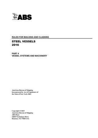
1.1 Organization of Part 4
Part 4 contains classification requirements for machinery. These requirements are organized in two broad
segments: that specific to equipment, and that specific to systems. 4-1-1/Figure 1 shows the overall organization
of Part 4.
FIGURE 1
Organization of Part 4
PART 4
RULES FOR MACHINERY
Chapter 1
CLASSIFICATION OF
MACHINERY
EQUIPMENT
REQUIREMENTS
SYSTEM
REQUIREMENTS
Chapter 2
PRIME
MOVERS
Chapter 4
BOILERS,
PRESSURE VESSELS
& FIRED EQUIPMENT
Chapter 3
PROPULSION &
MANEUVERING
MACHINERY
Chapter 5
DECK AND OTHER
MACHINERY
Chapter 6
PIPING
SYSTEMS
Chapter 8
ELECTRICAL
SYSTEMS
Chapter 7
FIRE SAFETY
SYSTEMS
Chapter 9
AUTOMATION
1.3 Requirements for Classification
1.3.1 Scopes of Part 4 and Part 5C
Part 4 provides the minimum requirements for machinery of self-propelled vessels of 90 meters in
length and over. Compliance with Part 4 is a condition for classification of all such vessels, and
for assigning the appropriate machinery class notations indicated in 4-1-1/1.5. Additional requirements
for machinery, which are specific for each vessel type, are provided in Part 5C. Compliance with
the provisions of Part 5C is a condition for assigning the vessel type class notation specified
therein, such as Oil Carrier, Passenger Vessel, Liquefied Gas Carrier, etc.
2 ABS RULES FOR BUILDING AND CLASSING STEEL VESSELS . 2016
11. Part 4 Vessel Systems and Machinery
Chapter 1 General
Section 1 Classification of Machinery 4-1-1
1.3.2 Fundamental Intent of Machinery Rules
1.3.2(a) Propulsion and maneuvering capability. Part 4 of the Rules is intended to assure the
propulsion and maneuvering capability of the vessel through specification of pertinent design,
testing and certification requirements for propulsion, maneuvering and other equipment and their
associated systems. See 4-1-1/Figure 1 for equipment and systems included in the scope.
1.3.2(b) Machinery hazards. Part 4 of the Rules is also intended to identify and address hazards
associated with machinery aboard a vessel, particularly those hazards which are capable of
causing personal injury, flooding, fire or pollution.
1.3.2(c) Cargo hazards. Hazards associated with cargoes carried (such as oil, dangerous goods,
etc.) or to the specialized operations of the vessel (such as navigating in ice) are addressed in Part 5C.
1.3.3 Application
Requirements in Part 4 are intended for vessels under construction; but they are to be applied to
alterations made to existing vessels, as far as practicable.
1.5 Classification Notations
Classification notations are assigned to a vessel to indicate compliance with particular portions of the
Rules. The following classification notations define compliance with specific requirements of the Rules for
machinery:
AMS indicates that a vessel complies with all machinery requirements in Part 4, other than the requirements
associated with the other classification notations below. AMS is mandatory for all self-propelled vessels.
ACC indicates that in a self-propelled vessel, in lieu of manning the propulsion machinery space locally, it
is intended to monitor the propulsion machinery space and to control and monitor the propulsion and
auxiliary machinery from a continuously manned centralized control station. Where such a centralized
control station is installed, the provisions of Section 4-9-5 are to be complied with. Upon verification of
compliance, ACC will be assigned.
ACCU indicates that a self-propelled vessel is fitted with various degrees of automation and with remote
monitoring and control systems to enable the propulsion machinery space to be periodically unattended
and the propulsion control to be effected primarily from the navigation bridge. Where periodically
unattended propulsion machinery space is intended, the provisions of Section 4-9-6 are to be complied
with. Upon verification of compliance, ACCU will be assigned.
APS indicates that a self-propelled vessel is fitted with athwartship thrusters. APS is optional for all self-
propelled vessels fitted with such thrusters and signifies compliance with applicable requirements of
Section 4-3-5.
PAS indicates that a non-self-propelled vessel is fitted with thrusters for the purpose of assisting the
movement or maneuvering. PAS is only assigned when requested by the Owner and signifies compliance
with applicable requirements of Section 4-3-5.
DPS-0, -1, -2, or -3 indicates that a vessel, self-propelled or non-self-propelled, is fitted with a dynamic
positioning system. The numerals (-0, -1, -2 or -3) indicates the degree of redundancy in the dynamic
positioning system. DPS is assigned only when requested by the owners and signifies compliance with the
ABS Guide for Dynamic Positioning Systems.
The above class notations, where preceded by the symbol À (Maltese cross; e.g., À AMS), signify that
compliance with these Rules was verified by ABS during construction of the vessel. This includes survey
of the machinery at the manufacturer’s plant (where required), during installation on board the vessel and
during trials.
Where an existing vessel, not previously classed by ABS, is accepted for class, these class notations are
assigned without À.
ABS RULES FOR BUILDING AND CLASSING STEEL VESSELS . 2016 3
12. Part 4 Vessel Systems and Machinery
Chapter 1 General
Section 1 Classification of Machinery 4-1-1
1.7 Alternative Standards
Equipment, components and systems for which there are specific requirements in Part 4 may comply with
requirements of an alternative standard, in lieu of the requirements in the Rules. This, however, is subject
to such standards being determined by ABS as being not less effective than the Rules. Where applicable,
requirements may be imposed by ABS in addition to those contained in the alternative standard to assure
that the intent of the Rules is met. In all cases, the equipment, component or system is subject to design
review, survey during construction, tests and trials, as applicable, by ABS for purposes of verification of
its compliance with the alternative standard. The verification process is to be to the extent as intended by
the Rules. See also 1-1-1/1.
1.9 Definitions
Definitions of terms used are defined in the chapter, sections or subsections where they appear. The
following are terms that are used throughout Part 4.
1.9.1 Control Station
A location where controllers or actuator are fitted, with monitoring devices, as appropriate, for
purposes of effecting desired operation of specific machinery.
Control Station is defined exclusively for purposes of Part 4, Chapter 7 “Fire Safety Systems,” as
intended by SOLAS, in 4-7-1/11.21.
Centralized Control Station is used in Part 4, Chapter 9 “Automation” to refer to the space or the
location where the following functions are centralized:
• Controlling propulsion and auxiliary machinery,
• Monitoring propulsion and auxiliary machinery, and
• Monitoring the propulsion machinery space.
1.9.2 Machinery Space
Machinery Space is any space that contains propulsion machinery, boilers, oil fuel units, steam
and internal combustion engines, generators and major electrical machinery, oil filling stations, air
conditioning and ventilation machinery, refrigerating machinery, stabilizing machinery or other
similar machinery, including the trunks to the space. Machinery space is to include “machinery
space of category A”, which, as defined in 4-7-1/11.15, is a space and trunks to that space which
contains:
• Internal combustion machinery used for main propulsion; or
• Internal combustion machinery used for purposes other than main propulsion where such
machinery has in the aggregate a total power output of not less than 375 kW (500 hp); or
• Any oil-fired boiler (including similar oil-fired equipment such as inert gas generators,
incinerators, waste disposal units, etc.) or oil fuel unit (see definition in 4-7-1/11.19).
1.9.3 Essential Services (2004)
For definition of essential services, see 4-8-1/7.3.3.
1.9.4 Hazardous Area
Areas where flammable or explosive gases, vapors or dust are normally present or likely to be
present are known as hazardous areas. Hazardous areas are, however, more specifically defined
for certain machinery installations, storage spaces and cargo spaces that present such hazard, e.g.:
• Helicopter refueling facilities, see 4-8-4/27.3.3;
• Paint stores, see 4-8-4/27.3.3;
• Cargo oil tanks and other spaces of oil carriers; see 5C-1-7/31.5;
• Ro-ro cargo spaces; see 5C-10-4/3.7.2.
4 ABS RULES FOR BUILDING AND CLASSING STEEL VESSELS . 2016
13. Part 4 Vessel Systems and Machinery
Chapter 1 General
Section 1 Classification of Machinery 4-1-1
1.9.5 Toxic or Corrosive Substances
Toxic Substances (solid, liquid or gas) are those that possess the common property of being liable
to cause death or serious injury or to harm human health if swallowed or inhaled, or by skin
contact.
Corrosive Substances (solid or liquid) are those, excluding saltwater, that possess in their original
stage the common property of being able through chemical action to cause damage by coming into
contact with living tissues, the vessel or its cargoes, when escaped from their containment.
1.9.6 Dead Ship Condition (2004)
Dead ship condition means a condition under which:
i) The main propulsion plant, boilers and auxiliary machinery are not in operation due to the
loss of the main source of electrical power, and
ii) In restoring propulsion, the stored energy for starting the propulsion plant, the main source
of electrical power and other essential auxiliary machinery is assumed to not be available.
1.9.7 Blackout (2004)
Blackout situation means the loss of the main source of electrical power resulting in the main and
auxiliary machinery to be out of operation.
3 Certification of Machinery
3.1 Basic Requirements
The Rules define, to varying degrees, the extent of evaluation required for products, machinery, equipment
and their components based on the level of criticality of each of those items. There are three basic
evaluation constituents:
• Design review; type/prototype testing, as applicable;
• Survey during construction and testing at the plant of manufacture; and
• Survey during installation on board the vessel and at trials.
Where design review is required by the Rules, a letter will be issued by ABS upon satisfactory review of
the plans to evidence the acceptance of the design. In addition to, or independent of, design review, ABS
may require survey and testing of forgings, castings and component parts at the various manufacturers’
plants, as well as survey and testing of the finished product. A certificate or report will be issued upon
satisfactory completion of each survey to evidence acceptance of the forging, casting, component or
finished product. Design review, survey and the issuance of reports or certificates constitute the
certification of machinery.
Based on the intended service and application, some products do not require certification because they are
not directly related to the scope of classification or because normal practices for their construction within
the industry are considered adequate. Such products may be accepted based on the manufacturers’
documentation on design and quality.
In general, surveys during installation on board the vessel and at trials are required for all items of
machinery. This is not considered a part of the product certification process. There may be instances,
however, where letters or certificates issued for items of machinery contain conditions which must be
verified during installation, tests or trials.
3.3 Type Approval Program (2003)
Products that can be consistently manufactured to the same design and specification may be Type
Approved under the ABS Type Approval Program. The ABS Type Approval Program is a voluntary
option for the demonstration of the compliance of a product with the Rules or other recognized standards.
It may be applied for at the request of the designer or manufacturer. . The ABS Type Approval Program
generally covers Product Type Approval (1-1-4/7.7.3), but is also applicable for a more expeditious
procedure towards Unit-Certification, as specified in 1-1-4/7.7.2.
See the “ABS Type Approval Program” in Appendix 1-1-A3.
ABS RULES FOR BUILDING AND CLASSING STEEL VESSELS . 2016 5
14. Part 4 Vessel Systems and Machinery
Chapter 1 General
Section 1 Classification of Machinery 4-1-1
3.5 Non-mass Produced Machinery (2003)
Non-mass produced critical machinery, such as propulsion boilers, slow speed diesel engines, turbines,
steering gears, and similar critical items are to be individually unit certified in accordance with the
procedure described in 4-1-1/3.1. However, consideration will be given to granting Type Approval to such
machinery in the category of Recognized Quality System (RQS). The category of Product Quality
Assurance (PQA) will not normally be available for all products, and such limitations will be indicated in
4-1-1/Table 1 through 4-1-1/Table 6. In each instance where Type Approval is granted, in addition to
quality assurance and quality control assessment of the manufacturing facilities, ABS will require some
degree of product specific survey during manufacture.
3.7 Details of Certification of Some Representative Products
4-1-1/Table 1 through 4-1-1/Table 6 provide abbreviated certification requirements of representative
machinery based on the basic requirements of the Rules for machinery. The tables also provide the
applicability of the Type Approval Program for each of these machinery items.
For easy reference, the tables contain six product categories as follows:
• Prime movers
• Propulsion, maneuvering and mooring machinery
• Electrical and control equipment
• Fire safety equipment
• Boilers, pressure vessels, fired equipment
• Piping system components
5 Machinery Plans
5.1 Submission of Plans (2011)
Machinery and systems plans required by the Rules are generally to be submitted electronically by the
manufacturer, designer or shipbuilder to ABS. However, hard copies will also be accepted. After review
and approval of the plans, one copy will be returned to the submitter, one copy will be retained for the use
of the ABS Surveyor, and one copy will be retained by ABS for record. Where so stated in the
shipbuilding contract, the Owner may require the builder to provide copies of approved plans and related
correspondence. A fee will be charged for the review of plans which are not covered by a contract of
classification with the shipbuilder.
In general, all plans are to be submitted and approved before proceeding with the work.
5.3 Plans
Machinery plans required to be submitted for review and approval by ABS are listed in each of the
sections in Part 4. In general, equipment plans are to contain performance data and operational particulars;
standard of compliance where standards are used in addition to, or in lieu of, the Rules; construction
details such as dimensions, tolerances, welding details, welding procedures, material specifications, etc.;
and engineering calculations or analyses in support of the design. System plans are to contain a bill of
material with material specifications or particulars, a legend of symbols used, system design parameters,
and are to be in a schematic format. Booklets containing standard shipyard practices of piping and
electrical installations are generally required to supplement schematic system plans.
7 Miscellaneous Requirements for Machinery
7.1 Construction Survey Notification
Before proceeding with the manufacture of machinery requiring test and inspection, ABS is to be notified
that survey is desired during construction. Such notice is to contain all of the necessary information for the
identification of the items to be surveyed.
6 ABS RULES FOR BUILDING AND CLASSING STEEL VESSELS . 2016
15. Part 4 Vessel Systems and Machinery
Chapter 1 General
Section 1 Classification of Machinery 4-1-1
7.3 Machinery Equations
The equations for rotating parts of the machinery in Part 4 of the Rules are based upon strength considerations
only and their application does not relieve the manufacturer from responsibility for the presence of dangerous
vibrations and other considerations in the installation at speeds within the operating range.
7.5 Astern Propulsion Power (2005)
7.5.1 General
Sufficient power for going astern is to be provided to secure proper control of the vessel in all
normal circumstances. The astern power of the main propelling machinery is to be capable of
maintaining in free route astern at least 70% of the ahead rpm corresponding to the maximum
continuous ahead power. For main propulsion systems with reversing gears, controllable pitch
propellers or electric propulsion drive, running astern is not to lead to overload of the propulsion
machinery. The ability of the machinery to reverse the direction of thrust of the propeller in
sufficient time, and so to bring the vessel to rest within a reasonable distance from maximum
ahead service speed, is to be demonstrated and recorded during trials.
7.5.2 Steam Turbine Propulsion
Where steam turbines are used for main propulsion, they are to be capable of maintaining in free
route astern at least 70% of the ahead revolutions for a period of at least 15 minutes. The astern
trial is to be limited to 30 minutes or is to be in accordance with manufacturer’s recommendation
to avoid overheating of the turbine due to the effects of “windage” and friction.
7.7 Dead Ship Start (2005)
Means are to be provided to bring the machinery into operation from a “dead ship” condition, as defined in
4-1-1/1.9.6. See 4-8-2/3.1.3 and 4-8-4/1.13 for the required starting arrangements.
7.9 Inclinations
Machinery installations are to be designed to ensure proper operations under the conditions as shown in
4-1-1/Table 7.
7.11 Ambient Temperature
For vessels of unrestricted service, ambient temperature, as indicated in 4-1-1/Table 8, is to be considered
in the selection and installation of machinery, equipment and appliances. For vessels of restricted or
special service, the ambient temperature appropriate to the special nature is to be considered.
7.13 Machinery Space Ventilation (2002)
Suitable ventilation is to be provided for machinery spaces so as to simultaneously allow for crew attendance
and for engines, boilers and other machinery to operate at rated power in all weather conditions, including
heavy weather. The main propulsion machinery space is to be provided with mechanical means of ventilation.
The supply of air is to be provided through ventilators which can be used in all weather conditions. In
general, ventilators necessary to continuously supply the main propulsion machinery space and the
immediate supply to the emergency generator room are to have coamings of sufficient height to eliminate
the need to have closing arrangements. See 3-2-17/9.3.
However, where due to the vessel size and arrangement this is not practicable, lesser heights for machinery
space and emergency generator room ventilator coamings may be accepted with provision of weathertight
closing appliances in accordance with 3-2-17/9.3.3 in combination with other suitable arrangements to ensure
an uninterrupted and adequate supply of ventilation to these spaces. See also 4-7-2/1.9.5 and 4-7-2/1.9.7.
7.15 Materials Containing Asbestos (2011)
Installation of materials which contain asbestos is prohibited.
ABS RULES FOR BUILDING AND CLASSING STEEL VESSELS . 2016 7
16. Part 4 Vessel Systems and Machinery
Chapter 1 General
Section 1 Classification of Machinery 4-1-1
9 Sea Trials
A final underway trial is to be made of all machinery, steering gear, anchor windlass, stopping and maneuvering
capability, including supplementary means for maneuvering, if any. Insofar as practicable, the vessel is to
be ballasted or otherwise arranged to simulate fully laden condition so as to allow propulsion machinery to
discharge its rated power. The entire machinery installation is to be operated in the presence of the
Surveyor in order to demonstrate its reliability and sufficiency to function satisfactorily under operating
conditions and its freedom from dangerous vibration and other detrimental operating phenomena at speeds
within the operating range. All automatic controls, including tripping of all safety protective devices that
affect the vessel’s propulsion system, are to be tested under way or alongside the pier, to the satisfaction of
the Surveyor. References are also to be made to the following for more detailed requirements:
• Steering gear trial: 4-3-4/21.7
• Anchor windlass trial: 4-5-1/9
• Remote propulsion control and automation trial: 4-9-9/5
• Shipboard trials for diesel engines: 4-2-1/15
The viscosity of the fuel used on the sea trial will be entered in the classification report.
Based on the sea trials, the following information is to be provided on board:
• Stopping time (see also 4-1-1/7.5),
• Vessel headings and distances recorded on sea trials, and
• For vessels with multiple propellers, ability to navigate and maneuver with one or more propellers
inoperative.
Reference may be made to IMO Resolution A.209(VII) Recommendation on Information to be Included in
the Maneuvering Booklet and IMO Resolution A.601(15) Recommendation on the Provision and the
Display of Maneuvering Information on board ships.
8 ABS RULES FOR BUILDING AND CLASSING STEEL VESSELS . 2016
17. Part 4 Vessel Systems and Machinery
Chapter 1 General
Section 1 Classification of Machinery 4-1-1
TABLE 1
Certification Details – Prime Movers (2014)
Prime Movers
ABS
Type Approval
Tier
Rule Reference
Section 1: Diesel Engines
1. Diesel engines ≥ 100 kW (135 hp), intended for propulsion and aux.
services essential for propulsion, maneuvering and safety of the
vessel
5
4-2-1/1.1, 4-2-1/13.1–13.9,
4-2-1/13.13, 4-2-1/15
2. Diesel engines that are mass produced per 4-2-1/13.11 4 4-2-1/13.11, 4-2-1/13.13, 4-2-1/15
3. Diesel engines < 100 kW (135 hp) 1 4-2-1/1.1
4. Diesel engines ≥ 100 kW (135 hp), intended for services not essential
for propulsion and aux. services for propulsion, maneuvering and
safety of the vessel
2 4-2-1/1.1, 4-2-1/7
Section 2: Turbochargers
5. Turbochargers for engines ≥100 kW (135 hp), intended for propulsion
and aux. services essential for propulsion, maneuvering and safety of
the vessel
5
4-2-2/1.1, 4-2-2/5.3.3,
4-2-2/11.1-11.5
6. Turbocharges that are mass produced per 4-2-2/11.3.2(b) 4 4-2-2/5.3.3, 4-2-2/11.1–11.5
7. Turbochargers for engines < 100 kW (135 hp) 1 4-2-2/1.1
Section 3: Gas Turbines
8. Gas turbines ≥ 100 kW (135 hp), intended for propulsion and aux.
services essential for propulsion, maneuvering and safety of the
vessel
5 4-2-3/1.1, 4-2-3/5.7, 4-2-3/13.1–13.5
9. Gas turbines that are mass produced per 4-2-3/13.3.2(b) 4 4-2-3/5.7, 4-2-3/13.1–13.5
10. Gas turbines < 100 kW (135 hp) 1 4-2-3/1.1
11. Gas turbines ≥ 100 kW (135 hp), intended for services not essential
for propulsion and aux. services for propulsion, maneuvering and
safety of the vessel
1/2 4-2-3/1.1, 4-2-3/7
Section 4: Steam Turbines
12. Steam turbines ≥ 100 kW (135 hp), intended for propulsion and aux.
services essential for propulsion, maneuvering and safety of the vessel
5 4-2-4/1.1, 4-2-4/13.1–13.5
13. Steam turbines that are mass produced per 4-2-4/13.3.2(b) 4 4-2-4/13.1–13.5
14. Steam turbines < 100 kW (135 hp) 1 4-2-4/1.1
15. Steam turbines ≥ 100 kW (135 hp), intended for services not
essential for propulsion and aux. services for propulsion,
maneuvering and safety of the vessel
1/2 4-2-4/1.1, 4-2-4/7
ABS RULES FOR BUILDING AND CLASSING STEEL VESSELS . 2016 9
18. Part 4 Vessel Systems and Machinery
Chapter 1 General
Section 1 Classification of Machinery 4-1-1
TABLE 2
Certification Details – Propulsion, Maneuvering and Mooring Machinery (2016)
Propulsion, Maneuvering and Mooring Machinery
ABS
Type Approval
Tier
Rule Reference
Section 1: Propulsion Shafting
1. Propulsion shafts 5 4-3-2/3.1–3.7
2. Couplings, coupling bolts 5 4-3-2/5.19
3. Cardan shafts 4/5 4-3-2/5.21
4. Couplings and coupling bolts built to a recognized standard 2 4-3-2/5.19
Section 2: Gears and Clutches
5. Gears and clutches ≥ 5590 kW (7500 hp) 5 4-3-1/9.7.1
6. Gears and clutches ≥ 100 kW (135 hp) 4/5 4-3-1/1.1, 4-3-1/9.7.2(c)
7. Gears and clutches < 100 kW (135 hp) 1 4-3-1/9.7.2(d)
Section 3: Propellers
8. Propellers, fixed and controllable pitch 5 4-3-3/7.3
9. Propulsion thrusters 5 4-3-5
10. (2016) Podded propulsion units 5 4-3-7 and 3-2-14/25
Section 4: Steering
11. Steering gears 5 4-3-4/19.1–19.7
12. Thrusters with APS or PAS notation 5 4-3-5/1.3 and 4-3-5/13
13. Dynamic positioning thrusters with DPS notation 5 DPS Guide
14. Other thrusters 375 kW (500 hp) or less 1 4-3-5/3.3.2
Section 5: Anchoring and Mooring
15. Anchor windlass 5 4-5-1/7
16. Mooring winches 1 4-5-1/1.3
10 ABS RULES FOR BUILDING AND CLASSING STEEL VESSELS . 2016
19. Part 4 Vessel Systems and Machinery
Chapter 1 General
Section 1 Classification of Machinery 4-1-1
ABS RULES FOR BUILDING AND CLASSING STEEL VESSELS . 2016 11
TABLE 3
Certification Details – Electrical and Control Equipment (2016)
Electrical and Control Equipment
ABS
Type Approval
Tier
Rule Reference
1. Generators and motors for essential services 100 kW (135 hp) 4/5 4-8-3/3, 4-8-5/3.13.1 (high voltage)
2. Motors 100 kW (135 hp) for LNG cargo or vapor handling services.
(See 5C-8-10/2.12)
4/5 5C-8-10/2.12, 4-8-3/3.17
3. Generators and motors for essential services < 100 kW (135 hp) 2 4-8-3/3.1
4. Motors < 100 kW (135 hp) for LNG cargo or vapor handling services.
(See 5C-8-10/2.12)
1 4-8-3/3
5. Propulsion generators and motors
5
4-8-3/3, 4-8-5/5.17.5, 4-8-5/3.13.1
(high voltage)
6. Switchboards (propulsion, main and emergency)
5
4-8-3/5.11.1, 4-8-5/3.13.2 (high
voltage)
7. Motor controllers for essential services (See 4-8-1/7.3.3) 100 kW
(135 hp) and for services indicated in 4-8-3/Table 7 100 kW (135 hp)
4/5 4-8-3/5.11.1
8. Motor controllers 100 kW (135 hp) for LNG cargo or vapor
handling services. (See 5C-8-10/2.12)
4/5 5C-8-10/2.12
9. Motor control centers including motor controller for essential services
(See 4-8-1/7.3.3) 100 kW (135 hp) and for services indicated in
4-8-3/Table 7 of aggregate load 100 kW (135 hp)
5 4-8-3/5.11.1
10. Motor controllers for steering gear (See 4-3-4/1.11) 5 4-8-3/5.11.1
11. Motor control centers 100 kW (135 hp) for LNG cargo or vapor
handling services. (See 5C-8-10/2.12)
4/5 4-8-3/5.11.1
12. Battery charger units of 25 kW and over, and discharging boards for
essential services (see 4-8-1/7.3.3), emergency and transitional source
of power (See 4-8-3/5.9)
4/5 4-8-3/5.11.1
13. Uninterruptible power system (UPS) units of 50 kVA and over for
essential services (see 4-8-1/7.3.3), and for services indicated in
4-8-3/Table 7, emergency source or transitional source of power
4/5 4-8-3/5.11.1
14. Distribution boards associated with the charging or discharging of the
battery system for emergency source and transitional source of power
4/5 4-8-3/5.11.1
15. Distribution boards associated with the uninterruptible power system
(UPS) units of 50 kVA and over for essential services (see 4-8-1/7.3.3),
for services indicated in 4-8-3/Table 7 and emergency source or
transitional source of power
4/5 4-8-3/5.11.1
16. Power transformers and converters of low voltage 2 4-8-3/7, 4-8-3/8
17. Non-sparking fans (See 4-8-3/11) 2 4-8-3/11
18. Plastic Cable Tray and Protective Casing (See 4-8-4/21.9.4 and
Appendix 4-8-4A1)
3 4-8-4/21.9.4, 4-8-4A1
19. Power transformers and converters for high voltage systems
exceeding 100 kVA
5 4-8-5/3.7.5(e)
20. Cables
1/3
4-8-5/3.13.3 (high voltage),
4-8-3/9.17
21. (2016) Propulsion cables 4/5 4-8-5/5.17.2
22. Circuit breakers and fuses 1 4-8-3/5.3.3, 4-8-3/5.3.4
23. Certified safe equipment 1/3 4-8-3/13.1
24. Governors 3 4-2-1/7.3.3iii), 4-9-8/13
25. Cable penetration devices 3 4-8-1/5.3.1
26. Semiconductor converters for propulsion 5 4-8-5/5.17.8
27. Generator prime mover remote control system 4/5 4-9-8/13
20. Part 4 Vessel Systems and Machinery
Chapter 1 General
Section 1 Classification of Machinery 4-1-1
TABLE 3 (continued)
Certification Details – Electrical and Control Equipment (2016)
Electrical and Control Equipment
ABS
Type Approval
Tier
Rule Reference
28. Remote auxiliary machinery control system 4/5 4-9-8/13
29. Centralized control and monitoring console 4/5 4-9-8/13
30. Control, monitoring and safety system devices, including computers,
programmable logic controllers, etc., for DPS, ACC and ACCU
notations
4/5 4-9-3/9.3.4, 4-9-3/11.9, 4-9-8/13.1
31. Complete assembly or subassembly units for DPS, ACC and ACCU
notations
4/5 4-9-3/9.3.4, 4-9-3/11.9, 4-9-8/13.1
32. Steering control system 5 4-3-4/13, 4-9-3/9.3.4, 4-9-3/11.9
33. Boiler control system (4-9-1/7.3) 5 4-4-1/11.5, 4-9-3/9.3.4, 4-9-3/11.9
34. CPP control system 5 4-9-3/9.3.4, 4-9-3/11.9
35. Computer-based System (Cat. II or III) for other than DPS, ACC or
ACCU notation
5 4-9-3/9.3.4, 4-9-3/11.9
12 ABS RULES FOR BUILDING AND CLASSING STEEL VESSELS . 2016
21. Part 4 Vessel Systems and Machinery
Chapter 1 General
Section 1 Classification of Machinery 4-1-1
TABLE 4
Certification Details – Fire Safety Equipment (2014)
Fire Safety Equipment
ABS
Type Approval
Tier(1)
Rule Reference
Section 1: Fire Detection and Alarm System Components
1. Fire detection and alarm system components 4 4-7-3/11
Section 2: Fixed Fire Extinguishing System Components
2. Fixed fire extinguishing system components 4 4-7-3/3
3. Fixed gas systems 4 4-7-3/3
4. Fixed foam systems 4 4-7-3/5 (IMO MSC/circ. 1165R)
5. Fixed water spray and water-mist systems 4 4-7-3/7
Section 3: Fireman’s Outfit, Hoses, and Portable Extinguishers
6. Fireman’s outfit 3 4-7-3/15.5
7. Fire hoses 3 4-7-3/1.13
8. Portable fire extinguishers 3 4-7-3/15.1
Note:
1 Type approval by flag Administration is acceptable in lieu of ABS Tier requirements.
ABS RULES FOR BUILDING AND CLASSING STEEL VESSELS . 2016 13
22. Part 4 Vessel Systems and Machinery
Chapter 1 General
Section 1 Classification of Machinery 4-1-1
TABLE 5
Certification Details – Boilers, Pressure Vessels and Fired Equipment (2014)
Boilers, Pressure Vessels and Fired Equipment
ABS
Type Approval
Tier
Rule Reference
Section 1: Group I
1. Group I boilers and pressure vessels 5 4-4-1/7
Section 2: Group II
2. Fired Pressure Vessels 5 4-4-1/7
3. Non-fired pressure vessels 4/5 4-4-1/7
4. Special Cases/Mass Produced 3/4 4-4-1/1
Section 3: Inert Gas Generators & Incinerators
5. Inert gas generators, incinerators 3 4-4-1/1
14 ABS RULES FOR BUILDING AND CLASSING STEEL VESSELS . 2016
23. Part 4 Vessel Systems and Machinery
Chapter 1 General
Section 1 Classification of Machinery 4-1-1
TABLE 6
Certification Details – Piping System Components (2014)
Piping System Components
ABS
Type Approval
Tier
Rule Reference
1. Pumps related to propulsion diesel engines (bore >300 mm) (11.8 in.)
and gas turbines and gears—fuel, cooling water, lube. Oil services
4/5 4-6-1/7.3.1, 4-6-1/7.5.3
2. Pumps related to propulsion steam plant and gears—fuel oil, lube.
Oil, condensate, main circulating, feed water services, vacuum pumps
for main condenser
4/5 4-6-1/7.3.1, 4-6-1/7.5.3
3. Hydraulic pumps of steering gears, controllable pitch propellers,
anchor windlass
4/5 4-6-1/7.3.1, 4-6-1/7.5.3
4. Pumps for fire main, emergency fire pumps, other fire service (fixed
water-based, sprinkler, foam), ballast, bilge, liquid cargoes, pumps
associated with inert gas
4/5 4-6-1/7.3.1, 4-6-1/7.5.3
5. Air compressors, cargo vapor compressors associated with LNG
carriers
4/5 4-6-1/7.3.1, 4-6-1/7.5.3
6. Steel pipes, classes I and II (except hydraulic piping) 4 4-6-1/7.5.1
7. Steel pipes, class III 3 4-6-1/7.5.1
8. Pipe fittings—flanges, elbows, tees, flexible joints, etc., and valves;
classes I & II designed to a recognized standard
3 4-6-1/7.5.2
9. Pipe fittings—flanges, elbows, tees, flexible joints, etc., and valves;
class III
2 4-6-1/7.5.2
10. Level 1 and 2 Plastic pipes and pipe joints with ISO9001 certifications 4 4-6-3/9, IACS UR P4
11. Level 1 and 2 Plastic pipes and pipe joints w/o ISO9001 certifications 5 4-6-3/9, IACS UR P4
12. Level 3 Plastic pipes and pipe joints 1 4-6-3/9, IACS UR P4
13. Hoses (Does not cover fire hoses. For fire hoses, see 4-1-1/Table 4) 2 4-6-2/5.7
14. Vent heads, pressure vacuum valves 2 4-6-2/7
15. Gauges, detectors and transmitters 2 4-6-2/9.11
16. Fluid power cylinders and systems, including valve actuators,
excluding steering actuators
2 4-6-7/3.5
ABS RULES FOR BUILDING AND CLASSING STEEL VESSELS . 2016 15
24. Part 4 Vessel Systems and Machinery
Chapter 1 General
Section 1 Classification of Machinery 4-1-1
TABLE 7
Design Angles of Inclination
Angle of Inclination, degrees (1)
Athwartship Fore-and-Aft
Installations, components Static Dynamic Static Dynamic
Propulsion and auxiliary machinery 15 22.5 5 (4)
7.5
Safety equipment
Emergency power installation (3) 22.5 22.5 10 10
Emergency fire pumps and their drives 22.5 22.5 10 10
Switchgear
Electrical and electronic appliances and control systems 22.5 (2)
22.5 (2)
10 10
Notes
1 Athwartship and fore-and-aft inclinations occur simultaneously.
2 Up to an angle of inclination of 45 degrees, switches and controls are to remain in their last set position.
3 In vessels designed for carriage of liquefied gases and of chemicals, the emergency power installation is to remain
operable with the vessel flooded to its permissible athwartship inclination up to a maximum of 30 degrees.
4 (2004) Where the length of the vessel exceeds 100 m (328 ft), the fore-and-aft static angle of inclination may be
taken as 500/L degrees, where L is the length of the vessel in meters (1640/L degrees, where L is the length of the
vessel in feet), as defined in 3-1-1/3.1.
16 ABS RULES FOR BUILDING AND CLASSING STEEL VESSELS . 2016
25. Part 4 Vessel Systems and Machinery
Chapter 1 General
Section 1 Classification of Machinery 4-1-1
TABLE 8
Ambient Temperatures for Unrestricted Service (2014)
Air
Installations,
Components
Location,
Arrangement (1, 2)
Temperature Range (°C)
Machinery and
electrical
installations
Enclosed Spaces – General 0 to +45
Components mounted on machinery
associated with high temperature
According to specific machinery and
installation
In spaces subject to higher
temperature (details to be submitted)
According to the actual maximum
ambient temperature
In spaces with temperature lower than
+45°C (details to be submitted)
According to the actual ambient
temperature subject to minimum +40
Open Deck −25 to +45
Water
Coolant Temperature (°C)
Seawater +32
Notes:
1 Electronic equipment is to be suitable for operations up to 55°C.
2 (2014) For environmentally controlled spaces, see 4-8-3/1.17.2.
ABS RULES FOR BUILDING AND CLASSING STEEL VESSELS . 2016 17
26. P A R T C h a p t e r 2 : P r i m e M o v e r s
4
C H A P T E R 2 Prime Movers
CONTENTS
SECTION 1 Diesel Engines...................................................................................... 24
1 General .............................................................................................24
1.1 Application .....................................................................................24
1.3 Definitions......................................................................................24
1.5 Increased Power Rating ................................................................24
1.7 Ambient Reference Conditions ......................................................25
1.9 Plans and Particulars to be Submitted...........................................25
3 Materials............................................................................................28
3.1 Material Specifications and Tests ..................................................28
3.3 Alternative Materials and Tests .....................................................28
5 Design...............................................................................................28
5.1 Bedplate/Crankcase ......................................................................28
5.3 Crankcase Doors...........................................................................28
5.5 Cylinders and Covers, Liners and Pistons.....................................28
5.7 Securing of Nuts ............................................................................29
5.9 Crankshafts ...................................................................................29
5.11 Shaft Couplings and Clutches .......................................................44
7 Engine Appurtenances......................................................................44
7.1 Explosion Relief Valves .................................................................44
7.2 Protection Against Crankcase Explosions .....................................46
7.3 Governors and Overspeed Protection ...........................................48
7.5 Governors and Overspeed Protection for Engines Driving
Generators.....................................................................................48
7.7 Materials, Fuel and Lube Oil Filters ...............................................50
7.9 Auxiliary Blowers ...........................................................................50
7.11 Fire Extinguishing System for Scavenge Manifold.........................50
7.13 Warning Notices ............................................................................50
7.15 Jacket Drain and Overpressure Protection....................................50
7.17 Monitoring......................................................................................50
7.19 Engine Turning Gear .....................................................................51
9 Piping Systems for Diesel Engines...................................................51
11 Installation of Diesel Engines............................................................51
11.1 Seating Arrangements for Diesel Engines .....................................51
11.3 Metal Chocks.................................................................................51
11.5 Cast Resin Chocks ........................................................................51
11.7 Resilient Mountings .......................................................................51
11.9 Hot Surfaces..................................................................................51
18 ABS RULES FOR BUILDING AND CLASSING STEEL VESSELS . 2016
27. 13 Testing, Inspection and Certification of Diesel Engines ...................52
13.1 Material and Nondestructive Tests................................................52
13.3 Hydrostatic Tests of Diesel Engine Components ..........................52
13.5 Relief and Safety Valves ...............................................................52
13.6 Manufacturer’s Quality Control......................................................52
13.7 Type Tests of Diesel Engines........................................................54
13.9 Shop Tests of Each Produced Diesel Engine................................58
13.11 Type Tests of Mass-produced Diesel Engines ..............................59
13.13 Certification of Diesel Engine ........................................................61
15 Shipboard Trials of Diesel Engines...................................................61
15.1 Engines Driving Fixed Pitch Propellers .........................................61
15.3 Engines Driving Controllable Pitch Propellers ...............................62
15.5 Engines Driving Propulsion Generators ........................................62
15.7 Engines Driving Generators or Essential Auxiliaries .....................62
15.9 Engines Burning Residual Fuel Oil................................................62
15.11 Torsional Vibration Barred Speed Range......................................62
TABLE 1 Required Material and Nondestructive Tests of Diesel
Engine Parts............................................................................63
TABLE 2 Test Pressures for Parts of Internal-combustion Engines ......64
FIGURE 1 Crank Throw for In Line Engine ..............................................30
FIGURE 2 Crank Throw for Vee Engine with 2 Adjacent
Connecting-Rods ....................................................................30
FIGURE 3 Reference Area of Crank Web Cross Section ........................31
FIGURE 4 Crankpin Section Through the Oil Bore..................................32
FIGURE 5 Crank Dimensions...................................................................37
FIGURE 6 Crank Throw of Semi-built Crankshaft....................................42
FIGURE 7 Limiting Curves for Loading 4-stroke Diesel Engines Step
by Step from No-load to Rated Power as Function of the
Brake Mean Effective Pressure ..............................................49
FIGURE 8 Type Test Power/Speed Diagram...........................................57
SECTION 1 Appendix 1 – Plans and Data for Diesel Engines .............................. 65
SECTION 1 Appendix 2 – Definition of Stress Concentration Factors in
Crankshaft Fillets ................................................................................. 72
SECTION 1 Appendix 3 –Stress Concentration Factors and Stress
Distribution at the Edge of Oil Drillings ............................................. 74
SECTION 1 Appendix 4 – Guidance for Spare Parts............................................. 76
1 General .............................................................................................76
3 Spare Parts for Main Propulsion Diesel Engines..............................76
5 Spare Parts for Auxiliary Diesel Engines..........................................77
ABS RULES FOR BUILDING AND CLASSING STEEL VESSELS . 2016 19
28. SECTION 1 Appendix 5 – Type Testing Procedure for Crankcase Explosion
Relief Valves ......................................................................................... 79
1 Scope................................................................................................79
3 Recognized Standards......................................................................79
5 Purpose.............................................................................................79
7 Test Facilities ....................................................................................79
9 Explosion Test Process ....................................................................80
11 Valves to be Tested ..........................................................................81
13 Method ..............................................................................................81
13.1 General Requirements...................................................................81
13.3 Stages of Testing...........................................................................81
15 Assessment and Records.................................................................82
17 Design Series Qualification...............................................................83
17.1 General..........................................................................................83
17.3 Flame Arrester...............................................................................83
17.5 Valves of Larger Sizes than Have Been Satisfactorily Tested .......83
17.7 Valves of Smaller Sizes than Have Been Satisfactorily Tested .....83
19 Reporting...........................................................................................84
21 Acceptance .......................................................................................84
SECTION 1 Appendix 6 – Type Testing Procedure for Crankcase Oil Mist
Detection and Alarm Equipment ......................................................... 85
1 Scope................................................................................................85
3 Recognized Environmental Test Standards .....................................85
5 Purpose.............................................................................................85
7 Test Facilities ....................................................................................85
9 Equipment Testing............................................................................86
9.1 For the Alarm/Monitoring Panel .....................................................86
9.3 For the Detectors...........................................................................86
11 Functional Tests................................................................................86
13 Detectors and Alarm Equipment to be Tested..................................87
15 Method ..............................................................................................87
17 Assessment.......................................................................................88
19 Design Series Qualification...............................................................88
21 Reporting...........................................................................................88
23 Acceptance .......................................................................................88
SECTION 1 Appendix 7 – Alternative Method for Calculation of Stress
Concentration Factors in the Web Fillet Radii of
Crankshafts by Utilizing Finite Element Method................................ 89
1 General .............................................................................................89
3 Model Requirements.........................................................................89
3.1 Element Mesh Recommendations.................................................89
3.3 Materials ........................................................................................90
3.5 Element Mesh Quality Criteria .......................................................91
20 ABS RULES FOR BUILDING AND CLASSING STEEL VESSELS . 2016
29. 5 Load Cases.......................................................................................91
5.1 Torsion ..........................................................................................91
5.3 Pure Bending (4 Point Bending)....................................................92
5.5 Bending With Shear Force (3 Point Bending)................................93
FIGURE 1 Oil Bore Proximity to Fillet.......................................................90
FIGURE 2 Boundary and Load Conditions for the Torsion Load Case....92
FIGURE 3 Boundary and Load Conditions for the Pure Bending
Load Case...............................................................................93
FIGURE 4 Boundary and Load Conditions for the 3-Point Bending
Load Case of an Inline Engine................................................94
FIGURE 5 Load Applications for In-line and V-type Engines...................95
SECTION 2 Turbochargers...................................................................................... 96
1 General .............................................................................................96
1.1 Application.....................................................................................96
1.3 Definitions......................................................................................96
1.5 Plans and Particulars to be Submitted ..........................................96
3 Materials............................................................................................97
3.1 Material Specifications and Purchase Orders................................97
3.3 Engines with Cylinder Bore ≤ 300 mm (11.8 in.) ...........................97
3.5 Engines with Cylinder Bore > 300 mm (11.8 in.) ...........................98
3.7 Alternative Material Test Requirements.........................................98
5 Design...............................................................................................98
5.1 Engines with Cylinder Bores ≤ 300 mm (11.8 in.)..........................98
5.3 Engines with Cylinder Bores > 300 mm (11.8 in.)..........................98
7 Piping Systems for Turbochargers ...................................................99
9 Installation of Turbochargers ............................................................99
9.1 Air Inlet ..........................................................................................99
9.3 Hot Surfaces..................................................................................99
9.5 Pipe and Duct Connections...........................................................99
11 Testing, Inspection and Certification of Turbochargers....................99
11.1 Shop Inspection and Tests............................................................99
11.3 Certification of Turbochargers .....................................................100
11.5 Engine and Shipboard Trials .......................................................101
13 Spare Parts .....................................................................................101
SECTION 3 Gas Turbines ...................................................................................... 102
1 General ...........................................................................................102
1.1 Application...................................................................................102
1.3 Definitions....................................................................................102
1.5 Plans and Particulars to be Submitted ........................................102
3 Materials..........................................................................................104
3.1 Material Specifications and Tests................................................104
3.3 Alternative Materials and Tests ...................................................104
ABS RULES FOR BUILDING AND CLASSING STEEL VESSELS . 2016 21
30. 5 Design.............................................................................................105
5.1 Rotors and Blades .......................................................................105
5.3 Operation Above the Rated Speed and Power............................105
5.5 Overhaul Interval .........................................................................105
5.7 Type Test Data ............................................................................105
5.9 Casing .........................................................................................105
7 Gas Turbine Appurtenances...........................................................106
7.1 Overspeed Protective Devices ....................................................106
7.3 Operating Governors for Propulsion Gas Turbines......................106
7.5 Operating Governors for Turbines Driving Electric
Generators...................................................................................106
7.7 Safety Systems and Devices .......................................................107
7.9 Hand Trip Gear............................................................................108
7.11 Air-intake Filters and Anti-icing ....................................................108
7.13 Silencers......................................................................................108
9 Piping and Electrical Systems for Gas Turbines.............................109
11 Installation of Gas Turbines ............................................................109
11.1 Pipe and Duct Connections .........................................................109
11.3 Intake and Exhaust......................................................................109
11.5 Hot Surfaces................................................................................109
13 Testing, Inspection and Certification of Gas Turbines....................109
13.1 Shop Inspection and Tests ..........................................................109
13.3 Certification of Gas Turbines .......................................................110
13.5 Shipboard Trials...........................................................................111
15 Spare Parts .....................................................................................111
TABLE 1 List of Alarms and Shutdowns ..............................................108
SECTION 3 Appendix 1 – Plans and Data for Gas Turbines............................... 112
SECTION 4 Steam Turbines .................................................................................. 114
1 General ...........................................................................................114
1.1 Application ...................................................................................114
1.3 Definitions....................................................................................114
1.5 Plans and Particulars to be Submitted.........................................115
3 Materials..........................................................................................116
3.1 Material Specifications and Tests ................................................116
3.3 Alternative Materials and Tests ...................................................116
5 Design.............................................................................................116
5.1 Casings........................................................................................116
5.3 Rotor Shafts.................................................................................117
5.5 Blades..........................................................................................117
5.7 Discs or Drums ............................................................................118
7 Steam Turbine Appurtenances .......................................................120
7.1 Overspeed Protective Devices ....................................................120
7.3 Operating Governors for Propulsion Turbines .............................120
22 ABS RULES FOR BUILDING AND CLASSING STEEL VESSELS . 2016
31. 7.5 Operating Governors for Turbines Driving Electric
Generators ..................................................................................120
7.7 Hand and Automatic Tripping......................................................121
7.9 Shaft Turning Gear......................................................................121
7.11 Overpressure Protection..............................................................121
9 Piping Systems for Steam Turbines ...............................................122
11 Installation of Steam Turbines ........................................................122
11.1 Exhaust Steam to Turbine...........................................................122
11.3 Extraction of Steam .....................................................................122
11.5 Pipe and Duct Connections.........................................................122
11.7 Hot Surfaces................................................................................122
13 Testing, Inspection and Certification of Steam Turbines................122
13.1 Shop Inspection and Tests..........................................................122
13.3 Certification of Steam Turbines ...................................................123
13.5 Shipboard Trials ..........................................................................124
SECTION 4 Appendix 1 – Guidance for Spare Parts........................................... 125
1 General ...........................................................................................125
3 Spare Parts for Propulsion Steam Turbines ...................................125
5 Spare Parts for Steam Turbines Driving Electric Generators.........125
ABS RULES FOR BUILDING AND CLASSING STEEL VESSELS . 2016 23
32. P A R T S e c t i o n 1 : D i e s e l E n g i n e s
4
C H A P T E R 2 Prime Movers
S E C T I O N 1 Diesel Engines
1 General
1.1 Application
Diesel engines having a rated power of 100 kW (135 hp) and over, intended for propulsion and for
auxiliary services essential for propulsion, maneuvering and safety (see 4-1-1/1.3) of the vessel, are to be
designed, constructed, tested, certified and installed in accordance with the requirements of this section.
Diesel engines having a rated power of less than 100 kW (135 hp) are not required to comply with the
provisions of this section but are to be designed, constructed and equipped in accordance with good
commercial and marine practice. Acceptance of such engines will be based on manufacturer’s affidavit,
verification of engine nameplate data, and subject to a satisfactory performance test after installation
conducted in the presence of the Surveyor.
Diesel engines having a rated power of 100 kW (135 hp) and over, intended for services considered not
essential for propulsion, maneuvering and safety, are not required to be designed, constructed and certified
by ABS in accordance with the requirements of this section. They are to comply with safety features, such
as crankcase explosion relief valve, overspeed protection, etc., as provided in 4-2-1/7, as applicable. After
installation, they are subject to a satisfactory performance test conducted in the presence of the Surveyor.
Piping systems serving diesel engines, such as fuel oil, lubricating oil, cooling water, starting air, crankcase
ventilation and exhaust gas systems are addressed in Section 4-6-5; hydraulic and pneumatic systems are
addressed in Section 4-6-7.
Requirements for turbochargers are provided in Section 4-2-2.
1.3 Definitions
For the purpose of this section, the following definitions apply:
1.3.1 Slow-, Medium-, High-speed Diesel Engines (2015)
Slow-Speed Engines means crosshead type diesel engines having a rated speed of less than 300 rpm.
Medium-Speed Engines means trunk piston type diesel engines having a rated speed of 300 rpm
and above, but less than 1400 rpm.
High-Speed Engines means trunk piston type diesel engines having a rated speed of 1400 rpm or
above.
1.3.2 Rated Power
The Rated Power is the maximum power output at which the engine is designed to run continuously
at its rated speed between the normal maintenance intervals recommended by the manufacturer.
1.5 Increased Power Rating
The rated power of an engine, which has been type tested as specified in 4-2-1/13.7 or 4-2-1/13.11 and
which has proven reliable in service, may be increased by not more than 10% of the type tested power
rating without performing any new type test, subject to prior approval of relevant plans and particulars.
24 ABS RULES FOR BUILDING AND CLASSING STEEL VESSELS . 2016
33. Part 4 Vessel Systems and Machinery
Chapter 2 Prime Movers
Section 1 Diesel Engines 4-2-1
1.7 Ambient Reference Conditions
The following ambient reference conditions are to be applied by the engine manufacturer for the purpose
of determining the rated power of diesel engines used on vessels with unrestricted service. However, the
engine manufacturer is not expected to provide simulated ambient reference conditions at any test.
Barometric pressure: 1 bar (1 kgf/cm2
, 15 psi)
Air temperature: 45°C (113°F)
Relative air humidity: 60%
Seawater Temperature (Charging air coolant inlet): 32°C (90°F)
1.9 Plans and Particulars to be Submitted
For a tabulated listing, see Appendix 4-2-A1.
1.9.1 Engine Construction
Engine transverse cross-section
Engine longitudinal section
Bedplate with welding details and procedures; frame/column with welding details and procedures;
crankcase with welding details and procedures
Structural supporting and seating arrangements
Arrangement of foundation bolts (for main engines only)
Thrust bearing assembly
Thrust bearing bedplate
Tie rod
Cylinder cover, assembly or cylinder head
Cylinder jacket or engine block
Cylinder liner
Crankshaft, details
Crankshaft, assembly
Thrust shaft or intermediate shaft (if integral with engine)
Coupling bolts
Counterweights (if not integral with crankshaft)
Connecting rod
Connecting rod, assembly and details
Crosshead, assembly and details
Piston rod, assembly and details
Piston, assembly and details
Camshaft drive, assembly
Arrangement of crankcase explosion relief valve and breather arrangement (only for engines having
a cylinder bore of 200 mm (8 in.) and above)
ABS RULES FOR BUILDING AND CLASSING STEEL VESSELS . 2016 25
34. Part 4 Vessel Systems and Machinery
Chapter 2 Prime Movers
Section 1 Diesel Engines 4-2-1
1.9.2 Engine Systems and Appurtenances (2001)
Starting air system
Fuel oil system
Lubricating oil system
Cooling water system
Governor arrangements
Schematic diagram of the engine control and safety system
Shielding and insulation of exhaust pipes, assembly
Shielding of high pressure fuel pipes, assembly as applicable
Turbochargers and superchargers, see 4-2-2/1.5
Couplings and clutches
Vibration damper assembly
Tuning wheel assembly, if fitted
Engine driven pump assembly
Scavenging pump and blower assemblies
1.9.3 Data
Type designation of engine and combustion cycle
Number of cylinders
Rated power, kW (PS, hp)
Rated engine speed, (rpm)
Sense of rotation (clockwise/counter-clockwise)
Firing order with the respective ignition intervals and, where necessary, V-angle, αv
Cylinder diameter, mm (in.)
Stroke, mm (in.)
Maximum cylinder pressure pmax, bar (kgf/mm2
, psi)
Mean effective pressure, bar (kgf/mm2
, psi)
Mean indicated pressure, bar (kgf/mm2
, psi)
Charge air pressure, bar (kgf/mm2
, psi), (before inlet valves or scavenge ports, whichever applies)
Nominal compression ratio
Connecting rod length LH, mm (in.)
Oscillating mass of one crank gear, kg (lb.), (in case of V-type engines, where necessary, also for
the cylinder unit with master and articulated type connecting rod or forked and inner connecting rod)
Mass of reciprocating parts, kg (lb.)
Digitalized gas pressure curve presented at equidistant intervals, bar (kgf/mm2
, psi) versus crank
angle, (intervals equidistant and integrally divisible by the V-angle, but not more than 5 degrees CA)
26 ABS RULES FOR BUILDING AND CLASSING STEEL VESSELS . 2016
35. Part 4 Vessel Systems and Machinery
Chapter 2 Prime Movers
Section 1 Diesel Engines 4-2-1
For engines with articulated-type connecting rod:
• Distance to link point LA, mm (in.)
• Link angle αN (degree)
• Connecting rod length (between bearing centers) LN, mm (in.)
• Tightening torques for pretensioned bolts and studs for reciprocating parts.
• Mass and diameter of flywheel and flywheel effect on engine
(2005) Operation and service manuals, including maintenance requirements for servicing and
repair and details of any special tools and gauges that are to be used with their fittings/settings,
together with any test requirements on completion of the maintenance (see also 4-6-2/9.6).
1.9.4 Materials
Crankshaft material:
• Material designation
• Mechanical properties of material (tensile strength, yield strength, elongation (with length of
specimen), reduction of area, impact energy)
• Type of forging (open die forged (free form), continuous grain flow forged, close die forged
(drop-forged), etc., with description of the forging process)
Crankshaft heat treatment
Crankshaft surface treatment
• Surface treatment of fillets, journals and pins (induction hardened, flame hardened, nitrided,
rolled, shot peened, etc., with full details concerning hardening)
• Hardness at surface
• Hardness as a function of depth, mm (in.)
• Extension of surface hardening
Material specifications of other main parts
1.9.5 Calculations and Analyses (2001)
Strength analysis for crankshaft and other reciprocating parts
Strength analysis for engine supports and seating arrangements
Torsional vibration analysis for propulsion shafting systems for all modes of operation including
the condition of one cylinder misfiring
Calculation demonstrating the adequacy of the bolting arrangement attaching tuning wheels or
vibration dampers to the propulsion system to withstand all anticipated torsional vibration and
operating loads
1.9.6 Submittals by Licensee
1.9.6(a) Plans lists. For each diesel engine manufactured under license, the licensee is to submit
two listings of plans and data to be used in the construction of the engine:
• One list is to contain drawing numbers and titles (including revision status) of the licenser’s
plans and data of the engine as approved by ABS (including approval information such as
location and date at which they are approved); and
• A second list, which is to contain the drawing numbers and titles (including revision status) of
the licensee’s plans and data, insofar as they are relevant to the construction of the engine. In
the event that construction is based solely on the licenser’s plans, this list will not be required.
ABS RULES FOR BUILDING AND CLASSING STEEL VESSELS . 2016 27
36. Part 4 Vessel Systems and Machinery
Chapter 2 Prime Movers
Section 1 Diesel Engines 4-2-1
1.9.6(b) Plans for approval. Any design change made by the licensee is to be documented, and
relevant plans and data are to be submitted by the licensee for approval or for information, as
appropriate. The licenser’s statement of acceptance of the modifications is to be included in the
submittal.
1.9.6(c) Plans for surveyor. A complete set of the licenser’s or the licensee’s plans and data, as
approved by ABS, is to be made available to the Surveyor attending the licensee’s plant.
3 Materials
3.1 Material Specifications and Tests
Material specifications are to be in accordance with that in Part 2, Chapter 3 or other specifications approved
under 4-2-1/3.3.1. Except as noted in 4-2-1/3.3, materials intended for engines required to be constructed
under survey are to be tested and inspected in accordance with 4-2-1/Table 1. The material tests, where so
indicated in the table, are to be witnessed by the Surveyor. Nondestructive tests in 4-2-1/Table 1 are to be
carried out by the manufacturer whose test records may be accepted by ABS.
Copies of material specifications or purchase orders are to be submitted to the Surveyor for information.
3.3 Alternative Materials and Tests
3.3.1 Alternative Specifications
Material manufactured to specifications other than those given in Part 2, Chapter 3 may be accepted,
provided that such specifications are approved in connection with the design and that they are
verified or tested in the presence of a Surveyor, as applicable, as complying with the specifications.
3.3.2 Steel-bar Stock
Hot-rolled steel bars up to 305 mm (12 in.) in diameter may be used when approved for any of the
items indicated in 4-2-1/Table 1, subject to the conditions specified in Section 2-3-8
3.3.3 Material for Engines of 375 kW (500 hp) Rated Power or Less
Material for engines having a rated power of 375 kW (500 hp) or less, including shafting,
couplings, and coupling bolts will be accepted on the basis of the material manufacturer’s certified
test reports and a satisfactory surface inspection and hardness check witnessed by the Surveyor.
Coupling bolts manufactured to a recognized bolt standard will not require material testing.
3.3.4 Engines Certified Under Quality Assurance Approval
For diesel engines certified under quality assurance assessment as provided for in 4-2-1/13.13.2(b),
material tests required by 4-2-1/3.1 need not be witnessed by the Surveyor; such tests are to be
conducted by the engine manufacturer whose certified test reports may be accepted instead.
5 Design
5.1 Bedplate/Crankcase
The bedplate or crankcase is to be of rigid construction, oiltight, and provided with a sufficient number of
bolts to secure the same to the vessel’s structure. See also 4-2-1/11.1 for seating of diesel engines.
5.3 Crankcase Doors (2006)
Crankcase construction and crankcase doors are to be of sufficient strength to withstand anticipated
crankcase pressures that may arise during a crankcase explosion taking into account the installation of
explosion relief valves required by 4-2-1/7.1. Crankcase doors are to be fastened and secured so that they
will not be readily displaced by a crankcase explosion.
5.5 Cylinders and Covers, Liners and Pistons
Cylinders, liners, cylinder covers and pistons, which are subjected to high temperatures or pressures, are to
be of materials suitable for the stresses and temperatures to which they are exposed.
28 ABS RULES FOR BUILDING AND CLASSING STEEL VESSELS . 2016
37. Part 4 Vessel Systems and Machinery
Chapter 2 Prime Movers
Section 1 Diesel Engines 4-2-1
5.7 Securing of Nuts
All nuts of main bearings and of connecting-rod bolts and all other moving parts are to be secured by split
pins or other effective locking means.
5.9 Crankshafts (2007)
5.9.1 General
5.9.1(a) Scope. These Rules for the design of crankshafts are to be applied to diesel engines for
propulsion and auxiliary purposes, where the engines are being so designed as to be capable of
continuous operation at their rated power when running at rated speed.
Where a crankshaft design involves the use of surface treated fillets, when fatigue testing is
conducted, or when direct stress (strain) measurements are taken, the relevant documents with
calculations/analysis and reliability data are to be submitted in order to substantiate the design.
5.9.1(b) Field of application. These Rules apply only to solid-forged and semi-built crankshafts
of forged or cast steel, with one crank throw between main bearings.
5.9.1(c) Principles of calculation. The design of crankshafts is based on an evaluation of safety
against fatigue in the highly stressed areas.
The calculation is also based on the assumption that the areas exposed to highest stresses are:
• Fillet transitions between the crankpin and web as well as between the journal and web,
• Outlets of crankpin oil bores.
When journal diameter is equal or larger than the crankpin diameter, the outlets of main journal oil
bores are to be formed in a similar way to the crankpin oil bores, otherwise separate
documentation of fatigue safety may be required.
Calculation of crankshaft strength consists of determining the nominal alternating bending (see
4-2-1/5.9.2) and nominal alternating torsional stresses (see 4-2-1/5.9.3) which, multiplied by the
appropriate stress concentration factors (see 4-2-1/5.9.4), result in an equivalent alternating stress
(uni-axial stress) (see 4-2-1/5.9.6). This equivalent alternating stress is then compared with the
fatigue strength of the selected crankshaft material (see 4-2-1/5.9.7). This comparison will show
whether or not the crankshaft concerned is dimensioned adequately (see 4-2-1/5.9.8).
5.9.2 Calculation of Alternating Stresses Due to Bending Moments and Radial Forces
5.9.2(a) Assumptions. The calculations are based on a quasi-static model where the steady
alternating loads are combined in a statically determined system. The statically determined system
is composed of a single crank throw supported in the center of adjacent main journals and subject
to gas and inertia forces. The bending length is taken as the length between the two main bearing
midpoints (distance L3, as per 4-2-1/Figure 1 and 4-2-1/Figure 2).
The bending moments MBR and MBT are calculated in the relevant section based on triangular
bending moment diagrams due to the radial component FR and tangential component FT of the
connecting-rod force, respectively (see 4-2-1/Figure 1).
For crank throws with two connecting-rods acting upon one crankpin the relevant bending
moments are obtained by superposition of the two triangular bending moment diagrams according
to phase (see 4-2-1/Figure 2).
i) Bending moments and radial forces acting in web. The bending moment MBRF and the
radial force QRF are taken as acting in the center of the solid web (distance L1) and are
derived from the radial component of the connecting-rod force.
The alternating bending and compressive stresses due to bending moments and radial
forces are to be related to the cross-section of the crank web. This reference section results
from the web thickness W and the web width B (see 4-2-1/Figure 3). Mean stresses are
neglected.
ABS RULES FOR BUILDING AND CLASSING STEEL VESSELS . 2016 29
38. Part 4 Vessel Systems and Machinery
Chapter 2 Prime Movers
Section 1 Diesel Engines 4-2-1
FIGURE 1
Crank Throw for In Line
Engine (2007)
FIGURE 2
Crank Throw for Vee Engine with
2 Adjacent Connecting-Rods (2007)
L1
L2
L3
// //
Centerlineof
ConnectingRod
L1
L2
L3
// //
L2
L1
Centerlines of
Connecting Rod
Connecting-rod
acting component forces
(FR
or FT)
Radial shear force diagrams
(QR
)
Bending moment diagrams
(MBR
or MBT
)
L1 = Distance between main journal centerline and crank web center
(see also 4-2-1/Figure 3 for crankshaft without overlap)
L2 = Distance between main journal centerline and connecting-rod center
L3 = Distance between two adjacent main journal centerlines
30 ABS RULES FOR BUILDING AND CLASSING STEEL VESSELS . 2016
39. Part 4 Vessel Systems and Machinery
Chapter 2 Prime Movers
Section 1 Diesel Engines 4-2-1
ABS RULES FOR BUILDING AND CLASSING STEEL VESSELS . 2016 31
FIGURE 3
Reference Area of Crank Web Cross Section (2007)
W
DG
E
DGS
2
B
Overlapped crankshaft
w
BL1
RH
Th
Wred
// //
Crankshaft without overlap
40. Part 4 Vessel Systems and Machinery
Chapter 2 Prime Movers
Section 1 Diesel Engines 4-2-1
32 ABS RULES FOR BUILDING AND CLASSING STEEL VESSELS . 2016
ii) Bending acting in outlet of crankpin oil bore. The two relevant bending moments are
taken in the crankpin cross-section through the oil bore.
The alternating stresses due to these bending moments are to be related to the cross-
sectional area of the axially bored crankpin.
Mean bending stresses are neglected.
FIGURE 4
Crankpin Section Through the Oil Bore (2007)
FR
FT
MBTO
MBRO
MBRO
is the bending moment of the radial
component of the connecting-rod force
MBTO is the bending moment of the tangential
component of the connecting-rod force
5.9.2(b) Calculation of nominal alternating bending and compressive stresses in web. The radial
and tangential forces due to gas and inertia loads acting upon the crankpin at each connecting-rod
position will be calculated over one working cycle.
Using the forces calculated over one working cycle and taking into account the distance from the
main bearing midpoint, the time curve of the bending moments MBRF, MBRO , MBTO and radial
forces QRF, as defined in 4-2-1/5.9.2(a)i) and 4-2-1/5.9.2(a)ii) will then be calculated.
In case of V-type engines, the bending moments – progressively calculated from the gas and
inertia forces – of the two cylinders acting on one crank throw are superposed according to phase.
Different designs (forked connecting-rod, articulated-type connecting-rod or adjacent connecting-
rods) are to be taken into account.
Where there are cranks of different geometrical configurations in one crankshaft, the calculation is
to cover all crank variants.
The decisive alternating values will then be calculated according to:
XN = minmax
2
1
XX
where
XN = considered as alternating force, moment or stress
Xmax = maximum value within one working cycle
Xmin = minimum value within one working cycle
41. Part 4 Vessel Systems and Machinery
Chapter 2 Prime Movers
Section 1 Diesel Engines 4-2-1
i) Nominal alternating bending and compressive stresses in web cross section. The calculation
of the nominal alternating bending and compressive stresses is as follows:
σBFN = e
eqw
BRFN
K
W
M 3
10
σQFN = e
RFN
K
F
Q
where
σBFN = nominal alternating bending stress related to the web, in N/mm2
MBRFN = alternating bending moment related to the center of the web, in N-m
(see 4-2-1/Figure 1 and 4-2-1/Figure 2)
= [ ]minmax
2
1
BFNBFN MM −
Weqw = section modulus related to cross-section of web, in mm3
=
6
2
WB •
Ke empirical factor considering to some extent the influence of adjacent
crank and bearing restraint
= 0.8 for 2-stroke engines
= 1.0 for 4-stroke engines
σQFN = nominal alternating compressive stress due to radial force related to
the web, in N/mm2
QRFN = alternating radial force related to the web, in N (see 4-2-1/Figure 1
and 4-2-1/Figure 2)
= [ ]minmax
2
1
RFRF QQ −
F = area related to cross-section of web, in mm2
= B • W
ii) Nominal alternating bending stress in outlet of crankpin oil bore. The calculation of nominal
alternating bending stress is as follows:
σBON = 3
10
e
BON
W
M
where
σBON = nominal alternating bending stress related to the crank pin diameter,
in N/mm2
MBON = alternating bending moment calculated at the outlet of crankpin oil
bore, in N-m
= [ ]minmax
2
1
BOBO MM −
MBO = (MBTO • cos ψ + MBRO • sin ψ)
ψ = angular position, in degrees (see 4-2-1/Figure 4)
ABS RULES FOR BUILDING AND CLASSING STEEL VESSELS . 2016 33
42. Part 4 Vessel Systems and Machinery
Chapter 2 Prime Movers
Section 1 Diesel Engines 4-2-1
We = section modulus related to cross-section of axially bored crankpin,
in mm3
=
−
D
DD BH
44
32
π
5.9.2(c) Calculation of alternating bending stresses in fillets. The calculation of stresses is to be
carried out for the crankpin fillet as well as for the journal fillet.
• For the crankpin fillet :
σBH = (αBσBFN)
where
σBH = alternating bending stress in crankpin fillet, in N/mm2
αB = stress concentration factor for bending in crankpin fillet (see 4-2-1/5.9.4)
• For the journal fillet (not applicable to semi-built crankshaft):
σBG = (βBσBFN + βQσQFN)
where
σBG = alternating bending stress in journal fillet, in N/mm2
βB = stress concentration factor for bending in journal fillet (see 4-2-1/5.9.4)
βQ = stress concentration factor for compression due to radial force in journal
fillet (determination as per 4-2-1/5.9.4)
5.9.2(d) Calculation of alternating bending stresses in outlet of crankpin oil bore.
σBO = (γBσBON)
where
σBO = alternating bending stress in outlet of crankpin oil bore, in N/mm2
γB = stress concentration factor for bending in crankpin oil bore (determination as
per 4-2-1/5.9.4)
5.9.3 Calculation of Alternating Torsional Stresses
5.9.3(a) General. The alternating torsional stresses that are to be used in determining the
equivalent alternating stress in the crankshaft are to be provided by the engine manufacturer, and
substantiated either by appropriate calculations, or by crankshaft fatigue testing.
Where applicable, the calculation for nominal alternating torsional stresses is to be undertaken by
the engine manufacturer according to the information contained in 4-2-1/5.9.3(b). In either case
supporting documentation is to be submitted for review.
5.9.3(b) Calculation of nominal alternating torsional stresses. The maximum and minimum
torques are to be ascertained for every mass point of the complete dynamic system and for the
entire speed range by means of a harmonic synthesis of the forced vibrations from the 1st order up
to and including the 15th
order for 2-stroke cycle engines and from the 0.5th
order up to and
including the 12th
order for 4-stroke cycle engines. Allowance must be made for the damping that
exists in the system and for unfavorable conditions (misfiring [*] in one of the cylinders). The
speed step calculation is to be selected in such a way that any resonance found in the operational
speed range of the engine is to be detected.
* Note: Misfiring is defined as cylinder condition when no combustion occurs but only a compression cycle.
34 ABS RULES FOR BUILDING AND CLASSING STEEL VESSELS . 2016