ABB WBT Indoor Fuses IEC Standard 1.9kV-4kV - ABB Medium Voltage Indoor Railway DC Fuses
•
1 like•955 views

This document provides information on 36 Fuses Indoor Railway DC Fuses type WBT, including: - An overview of the features, applications, climatic working conditions, designations, versions, technical data, compliance with standards, ordering process, and examples. - Tables listing the fuse link types and their applications, compliance with standards, and suitable fuse base types. - Sections on general technical data for fuse links and fuse boards, including highest operating voltage, rated current, switching overvoltage, rated breaking current, weight, and resistance. - Appendices with diagrams showing cut-off current characteristics and time-current characteristics for various fuse link types.

Recommended
Recommended
More Related Content
What's hot
What's hot (20)
Similar to ABB WBT Indoor Fuses IEC Standard 1.9kV-4kV - ABB Medium Voltage Indoor Railway DC Fuses
Similar to ABB WBT Indoor Fuses IEC Standard 1.9kV-4kV - ABB Medium Voltage Indoor Railway DC Fuses (20)
More from Thorne & Derrick International
More from Thorne & Derrick International (20)
Recently uploaded
Recently uploaded (20)
ABB WBT Indoor Fuses IEC Standard 1.9kV-4kV - ABB Medium Voltage Indoor Railway DC Fuses
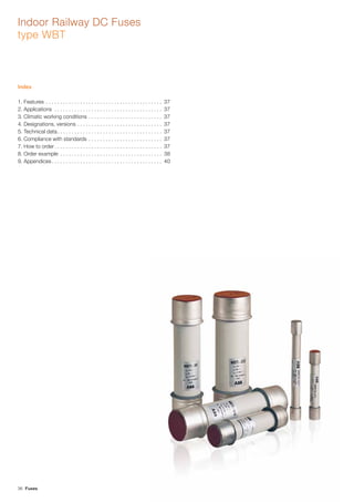
- 1. 36 Fuses Indoor Railway DC Fuses type WBT Index 1. Features . . . . . . . . . . . . . . . . . . . . . . . . . . . . . . . . . . . . . . . . . 37 2. Applications . . . . . . . . . . . . . . . . . . . . . . . . . . . . . . . . . . . . . . 37 3. Climatic working conditions . . . . . . . . . . . . . . . . . . . . . . . . . . 37 4. Designations, versions . . . . . . . . . . . . . . . . . . . . . . . . . . . . . . 37 5. Technical data. . . . . . . . . . . . . . . . . . . . . . . . . . . . . . . . . . . . . 37 6. Compliance with standards . . . . . . . . . . . . . . . . . . . . . . . . . . 37 7. How to order . . . . . . . . . . . . . . . . . . . . . . . . . . . . . . . . . . . . . . 37 8. Order example . . . . . . . . . . . . . . . . . . . . . . . . . . . . . . . . . . . . 38 9. Appendices. . . . . . . . . . . . . . . . . . . . . . . . . . . . . . . . . . . . . . . 40
- 2. Fuses 37 1. Features – simple design, – high rupturing capacity, – short circuit current limiting, – low switching voltages, – R1, P1 fire-protection grade for the materials used – in accordance with PN-84/K-02500. 2. Applications The fuse links for traction applications are used to protect traction substation and electric traction rolling stock equipment against the effects of overloads greater than 2 x I and of short-circuits at voltages of 1.9 kV DC and 4 kV DC. Please refer to Table 1 for application details for particular product types. 3. Climatic working conditions Fuse base type PBWMI can be operated indoors at ambient temper- atures ranging from -5°C to +50°C. Other parameters are presented below. The fuse links and fuse boards can be operated indoors or in sealed boxes secured under the railway car under the following environmental conditions: – at ambient temperatures ranging from -30°C to +50°C, – in ambient air with are relative humidity of 95% at a temperature of +20°C, – at an altitude of 1 200 m. All other operating conditions first require approval from the manufacturer. 4. Designations, versions 4.1 Marking system The marking system for particular fuse link, fuse base or fuse board has three alphanumerical sections as shown in the following diagram. WBTI - 3 / 3 Fuse link type Rated voltage Rated current TBT2 - 3 / 20 Fuse board Rated voltage Rated current base type current 5. Technical data The general technical data of the fuse links are presented in Table 3. The general technical data of the fuse boards are presented in Table 4. 6. Compliance with standards Fuse links for traction applications meet the requirements specified in Table 2. 7. How to order Order by specifying the following: – product name, – type symbol, – rated voltage, – rated current, – quantity. All additional requirements not listed in this catalogue should be agreed with the manufacturer.
- 3. 38 Fuses 8. Order example 1. Type WBTI-3/30 fuse link for traction applications with a rated voltage of 4kV, rated current of 20 A – 20 pcs. 2. Type TBT2-3/20 fuse board for traction applications with a rated voltage of 4 kV, rated current of 20 A – 20 pcs. Table 1. Fuse link type Applications WBTI-3/3 to 20 WBTI-3/25 to 50 WBTI-3/80 Protection against the effects of short-circuits and overloads in the electric circuits of railway traction substation equipment. WBTI-3/3 to 20 WBTI-3/25 to 50 Protection against the effects of short circuits and overload in the electric circuits of traction vehicles, railcoach space- -heating equipment and electric locomotive. WBTG-3/3; 4; 6 WBTG-3/3-I Protection against the effects of short circuits and overloads in electric single and multi-voltage circuits of rail coach space- -heating equipment. WBTGI-3/10; 16; 20 Protection against the effect of short-circuits and overloads in the electric single- and multi- voltage circuits of rail-coach space-heating equipment as well as other d.c. circuits at traction vehicles. The dimension of these fuse- links meet the requirements of German Standards DIN 43625. WBTS-3/0,6; 1 Protection against the effects of short-circuits and overloads in the voltage measurement circuits and special electric equipment in traction vehicles, if the nominal loads are lower than 1 A. WBT-1,5/3; 15; 40 Protection against the effects of short circuits and overloads in electric circuits of traction substation equipment and vehicles operating at a rated voltage not greater than 1 900 V DC. Table 2. Product type Compilance with Standards WBTI-3/3 to 80 PN-69/E-06120 in scope of environmental requirements and vibration and shock resistance. General Requirements according to PN-E-06172:1999, IEC Publ. 77 of 1968 as well as UIC 552VSheets, VII edition. WBTG-3/3 to 6 WBTG-3/3-I PN-69/E-06120 in scope of environmental requirements and vibration and shock resistance. General Requirements according to PN-E-06172:1999, IEC Publ. 77 of 1968 as well as UIC 552VSheets of 1993. WBTGI-3/10 to 20 VII edition PN-69/E-06120 in scope of environmental requirements and vibration and shock resistance. DIN 43625 in scope of dimensional requirements General Requirements according to PN-E-06172:1999-14, IEC Publ. 77 of 1968 as well as UIC 552VSheets. WBTS-3/0,6; 1 PN-69/E-06120 in scope of environmental requirements and vibration and shock resistance. General Requirements acc. PN-E-06172:1999-14 IEC Publ. 77 of 1968. WBT-1,5/3; 15; 40 PBT-1,5/40 WTO-67/ZPM Technical Requirements and AE/A10-15004. The fuse boards for traction applications meet the requirements of the following Standards: PN-E-06172 in the scope specifi ed above. Fuse type Fuse base type suitable for selected fuse types WBTI-3/3; WBTI-3/6; WBTI-3/10; WBTI-3/16; WBTI-3/20 PBWMI-6/20, TBT2-3/20 i 50,TBTS2-3/20 i 50, TBTS 2-3/20,TBT2-3/20 WBTI-3/25; WBTI-3/32; WBTI-3/40 PBWMI-6/40,TBT2-3/20 i 50,TBTS2-3/20 i 50,TBT2-3/50 WBTI-3/50 TBT2-3/20 i 50,TBTS2-3/20 i 50,TBT2-3/53 WBTI-3/80 PBWMI-10/100-1 WBTGI-3/10; WBTGI-3/16; WBTGI-3/20 TBTG1A-3/15 WBTG-3/3-I PBPM-6 WBTG-3/3; WBTG-3/4; WBTG-3/6 TBTG1-3/6 WBTS-3/0,6; WBTS-3/1 TBTS1-3/1 WBT-1,5/3; WBT-1,5/15; WBT-1,5/40 PBT-1,5/40 Other configurations should be agreed with manufacturer.
- 4. Fuses 39 General technical data of fuse links for traction applications Table 3. Fuse link type Highest ope- rating voltage Rated current Switching overvolt. Rated breaking current Weight Resistance acc PN-E- 06172:1999-14 acc UIC-552 Un In In UTRV I1 Min. Max [kV] DC [A] DC [A] DC [kV] [kA] [kg] [mΩ] [mΩ] WBTI-3/3 3.7501) 3 3.5 <12 31.5 1.5 516.6 631.4 WBTI-3/6 6 7 189 231 WBTI-3/10 10 10 130.5 159.5 WBTI-3/16 16 16 64.8 79.2 WBTI-3/20 20 20 41.4 50.6 WBTI-3/25 25 25 2.3 33.3 40.7 WBTI-3/32 32 32 28.8 35.2 WBTI-3/40 40 36 20.7 25.3 WBTI-3/50 50 48 15.8 19.25 WBTI-3/80 80 - 4.6 8.73 10.67 1) While testing the breaking capacity, satisfactory results were found for the short-circuit range at recovery voltage of 4 000 V DC. For the overload currents at a recovery voltage of between 3 800-4 000 V DC, various values for particular fuse were obtained. The resistances are me- asured using either an electrical bridge method or a measuring instrument with an accuracy class not worse that 0.5% at an ambient temperature of t = 20°C ± 2°C. Fuse link type Highest operating voltage Rated current Switching overvolt. Rated breaking current Weight Resistance acc PN-E- 06172:1999 acc UIC-552 Un In In UTRV I1 Min. Max. [kV] DC [A] DC [A] DC [kV] [kA] [kg] [mΩ] [mΩ] WBTGI-3/10 3.750 10 10 <12 31.5 0.65 137.7 168.3 WBTGI-3/16 16 16 69.3 84.7 WBTGI-3/20 20 20 45.1 55.3 WBTG-3/3-I 4 3 3 <12 40 0.13 569.7 696.3 WBTG-3/3 4 3 3 <12 40 0.22 569.7 696.3 WBTG-3/4 3.5 4 459 561 WBTG-3/6 6 6 300.6 367.4 WBTS-3/0.6 4 0.6 - <12 40 0.08 42(Ω) 51.3(Ω) WBTS-3/1 1 - 1710 2090 WBT-1.5/3 1950 3 - <6 50 0.5 234 316 WBT-1.5/15 15 - 28.2 38.2 WBT-1.5/40 40 - 1.25 11.3 15.3 General technical data of fuse boards Table 4. Fuse board type; Fuse base type Rated voltage Rated current Rated test voltage at 50 Hz Number of poles Weight Un In Ut [kV] DC [A] DC [kV] [pcs] [kg] PBWMI-6/20 7.2 20 351) 1 4.9 PBWMI-6/50 40 5 TBT2-3/20 4 20 10 2 5.5 TBT2-3/20 & 502) 20&50 5.65 TBT2-3/50 50 5.8 TBTS2-3/20 20 7.0 TBTS2-3/20 & 50 20&50 2 7.3 TBTG1A-3/15 20 1 1.15 TBTG1-3/6 6 0.85 TBTS1-3/1 4 1 10 1 0.35 PBT-1.5/40 1.9 40 271) 353) 1 3.6 PBWMI-10/100-1 12 100 - 1 5.6 Note: Due to the introduction of improvements, we reserve the right to modify the products. 1) AC contact-to-contact insulation test voltage. 2) One pole is designed for fixing the type WBTI-3/3 to 20 fuse link and the second one for WBTI-3/25 to 50 fuse link. 3) AC earth insulation test voltage.
- 5. 40 Fuses 10 1 0.2 0.2 1 10 40 80A 32A 40A 25A 20A 16A 10A 6A 9. Appendices Fig.1 Cut-off current characteristics for fuse link types WBTI-3... Fig. 2 Time-current characteristics for fuse link types WBTI-3 ... Current value deviations for any average pre-arcing period value as read from the diagram are presented within ±20% Ipeak[kA] Ip [kA] 6A 10A 16A 20A 25A 32A 40A 80A 1000 100 10 1 0.1 0.01 10 100 1000 3000 Prospective current [A] Pre-arcingtime[s]
- 6. Fuses 41 Fig. 3 Cut-off current characteristics fuse link types WBTGI-3 ... Fig. 4 Time-current characteristics for fuse link types WBTGI-3 ... Current value deviations for any average pre-arcing period value as read from the diagram are presented within ±20% 10A 16A 20A 1000 100 10 1 0.1 0.01 10 100 600 Pre-arcingtime[s] 10 1 0.2 0.2 1 10 40 20A 16A 10A Ipeak[kA] Ip [kA] Prospective current [A]
- 7. 42 Fuses Ipeak[kA] Prospective current [A] 0.02 0.04 0.06 0.08 0.1 0.2 0.4 0.6 0.8 1 2 0.1 0.2 0.4 0.6 0.8 1 2 4 6 8 10 20 40 50 6A 4A 3A 1000 600 400 200 100 60 40 20 10 6 4 2 1 0.6 0.4 0.2 0.1 0.06 0.04 0.02 0.01 3A 4A 6A 4 6 8 10 20 40 60 80100 200 0.02 0.04 0.06 0.08 0.1 0.2 0.4 0.6 0.8 1 2 0.1 0.2 0.4 0.6 0.8 1 2 4 6 8 10 20 40 50 6A 4A 3A 1000 600 400 200 100 60 40 20 10 6 4 2 1 0.6 0.4 0.2 0.1 0.06 0.04 0.02 0.01 3A 4A 6A 4 6 8 10 20 40 60 80100 200 Fig. 5 Cut-off current characteristics for fuse link types WBTG-3/3; 4; 6... and WBTG-3/3-I Fig. 6 Time-current characteristics for fuse link types WBTG-3/3; 4; 6... and WBTG-3/3-I. Current value deviations for any average pre-arcing period value as read from the diagram are presented within ±20%. Ip [kA] Pre-arcingtime[s]
- 8. Fuses 43 Fig. 7 Cut-off current characteristics for fuse link types WBTS-3/0.6; 1 Fig. 8 Time-current characteristics for fuse link types WBTS-3/0.6; 1 Current value deviations for any average pre-arcing period value as read from the diagram are presented within ±20%. 0.1 0.2 0.4 0.6 1 10 20 40 50 0.02 0.04 0.06 0.08 0.1 0.2 0.4 0.6 0.8 1 2 1A 0.6A 0.6A 1A 1000 100 10 1 0.1 0.01 1 10 40 Ipeak[kA]Pre-arcingtime[s] Ip [kA] Prospective current [A]
- 9. 44 Fuses Fig. 9 Cut-off current characteristics for fuse link types WBT-1.5/3; 15; 40 Fig. 10 Time-current characteristics for fuse link types WBT-1.5/3; 15; 40. Current value deviations for any average pre-arcing period value as read from the diagram are presented within ±20%. 1000 100 10 1 0.1 0.01 4 10 40 100 1100 3A 15A 40A 0.2 0.4 0.6 0.8 1 2 4 6 8 10 20 0.1 0.2 0.4 0.6 1 10 20 40 50 40A 15A 3A Ipeak[kA] Ip [kA] (rms) Current [A] Pre-arcingtime[s]
- 10. Fuses 45 WBTI-3, WBTG-3, WBTGI-3, WBTG-3/3-I,WBTS-3 and WBT-1.5 fuse links for traction applications Fuse link type Dimensions [mm] ØA ØD ØC K E e WBTI-3/3 to 20 55 62 66 50 20 256±2 WBTI-3/25 to 50 70 78 84 WBTGI-3/10 to 20 38 45 50 33 256±2 WBTG-3/3-I 18 23 - 25 - 209±2 WBTG-3/3 to 6 24 28 - 20 12 200±2 WBTS-3/0.6; 1 18 23 - 25 - 145±2 WBT-1.5/3;15 38 45 50 33 - 109±2 WBT-1.5/40 65 72 - - - 109±2 e K E E ∅A ∅D ∅A K E ∅D ∅C e ∅D ∅C K E ∅A e ∅45 ∅D ∅A 33 60 30 13 ∅41 ∅45 ∅8 O∅8 254 -0,5 e Type WBTI-3-3/... fuse links Type WBTGI-3/...; WBT-1,5/3 ... fuse links Type WBTG-3/3-6, WBTG-3/3-I; WBTS-3/... fuse links Type WBT-1,5/40 fuse links