surveyors in Removable partial Dentures/RPD
•Download as PPT, PDF•
14 likes•2,185 views

surveyors in Removable partial Dentures/RPD ppt for BDS undergraduate students

Recommended
More Related Content
What's hot
What's hot (20)
Similar to surveyors in Removable partial Dentures/RPD
Similar to surveyors in Removable partial Dentures/RPD (20)
More from Anil Goud
More from Anil Goud (17)
Recently uploaded
Recently uploaded (20)
surveyors in Removable partial Dentures/RPD
- 2. DEFINITION Instrument used to determine the relative parallelism of two or more surfaces of the teeth or other parts of the cast of a dental arch. • www.asiandentalacademy.org
- 3. PURPOSES • Modifications of oral structure that are necessary to fabricate a RPD. • Surveying the diagnostic cast , • Recon touring abutment teeth on the diagnostic cast , • Contouring wax patterns • Measuring a specific depth of under cut • Surveying ceramic veneer crowns • Placing intra coronal retainers • Placing internal rests, • Blocking out the master cast • www.asiandentalacademy.org
- 4. TYPES • Ney • Jelenko. • Advanced • www.asiandentalacademy.org
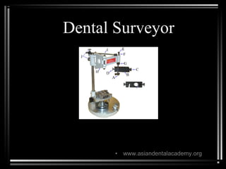
- 7. Parts of surveyor • Platform- on which base is moved , • Vertical Arm-supports super structure • Horizontal Arm- surveying tool suspends • Base- table swivels • www.asiandentalacademy.org
- 8. • Paralleling tool or Guide line marker • Mandrel- holding special tools • Table – cast is attached • www.asiandentalacademy.org
- 9. • Ney’s • First Surveyor • Arm is fixed • Vertical arm is retained by friction with in a fixed bearing • Jelenko Arm is swivels • Vertical arm is spring mounted and returns to the top position when it is released. • Horizontal arm made to swivel • www.asiandentalacademy.org
- 12. SURVEYING DIAGNOSTIC CAST • Objectives- • To determine path of placement – Path of placement is the direction in which a restoration moves from the point of initial contact with the supporting teeth to its terminal resting position • To identify proximal tooth surfaces that are need to be made parallel, so that they act as guiding planes. • To locate and measure areas of teeth that may be used for retention • To permit and accurate charting of the mouth preparation to be made. • www.asiandentalacademy.org
- 13. • To delineate the height of contour on abutment teeth and to locate areas of undesirable tooth under cuts that are to be avoided’ • To record the cast position in relation to the selected path of placement for future reference. • www.asiandentalacademy.org
- 14. CONTOURING WAX PATTERNS • The surveying blade is used as a wax carver during this phase of mouth preparation so that the proposed path of placement may be maintained throughout the preparation of cast restoration for abutment teeth. • Guiding planes on all proximal surfaces of the wax patterns adjacent to edentulous areas should be made parallel to the previously determined path of placement. • Those surfaces of restoration that are to provide retention for clasp arms should be contoured so that retentive clasp may be placed in the cervical third of the crown for best esthetic advantage. • www.asiandentalacademy.org
- 16. SURVEYING CERAMIC VENEER CROWNS • Ceramic veneer crowns are often used to restore abutment teeth on which extra coronal direct retainers will be placed. • Surveyor is used to contour all areas of the wax patterns for the veneer crown except for the buccal or labial surface. • www.asiandentalacademy.org
- 17. PLACEMENT OF INTRA CORONAL RETAINERS • Surveyor is used as follows:- • To select the path of placement in relation to the long axis of the abutment teeth that will avoid areas of interference. • To carve recesses in wax patterns, to place internal attachment trays in wax patterns , to cut recesses in castings with the hand piece holder. • To place key way portion of the attachment in the casting before investing and soldering . • www.asiandentalacademy.org
- 18. PLACEMENT INTERNAL REST SEATS • Surveyor may be used as a drill press with a dental hand piece attached to the vertical arm by a hand piece holder. • internal rest seats may be carved in the wax pattern and further refined with the hand piece after casting , or the entire rest seat may be cut in cast restoration with the hand piece. • It is best to carve the outline form of rest seat in the wax and refine the casting with the hand piece. • Internal rest in partial denture construction provides a positive occulusal support ,horizontal stabilization through the parallelism of vertical walls. • www.asiandentalacademy.org
- 19. MACHINING CAST RESTORATION • With hand piece holder attached, axial surface of cast and ceramic restoration may be refined by machining with a suitable cylindrical carborundrum point. • Proximal surfaces of crowns and inlays ,which will serve has guiding planes and vertical surfaces above crown ledges may be improved by machining. • www.asiandentalacademy.org
- 20. SURVEYING MASTER CAST • surveying master cast follows • Mouth preparation, path of placement ,location of retentive areas and location of remaining interference must be known before proceeding with final design of denture frame work. • www.asiandentalacademy.org
- 21. Objectives- • To select the most suitable path of placement that satisfy the requirements of guiding planes retention ,noninterference and esthetics. • To locate undesirable under cut areas . • To permit measurements of retentive areas and to identify the location of clasp terminals and flexibility of clasp arm being used . • To trim blackout material parallel to the path of placement before duplication • www.asiandentalacademy.org
- 23. FACTORS THAT DETERMINE PATH OF PLACEMENT AND REMOVAL • Guiding planes- • Retentive areas – • Interference- • Esthetics- • www.asiandentalacademy.org
- 24. • GUIDING PLANES- • Proximal tooth surfaces that bear a parallel relation ship to one another must either the found or be created to act has guiding planes during placement and removal of prosthesis. • These are necessary to ensure predictable clasp assembly function, including retention and stabilization . • For a clasp retentive its retentive arm must be forced to flex. • These are necessary to give a positive direction to the moment of the restoration. • www.asiandentalacademy.org
- 25. • RETENTIVE AREAS- • Retentive areas must exist for a given path of placement and must be contacted by retentive clasp arm ,which are forced to flex over a convex surface during placement and removal. • www.asiandentalacademy.org
- 26. • INTERFERENCE- • The prosthesis must be designed so that it may be placed and removed without encountering tooth or soft tissue interference. • It may be eliminated during mouth preparation by surgery ,modifying interfering tooth surfaces or altering tooth contours. • www.asiandentalacademy.org
- 27. • ESTHETICS- • Less Clasp Metal & Base Material may be displayed. • It also detects choice of path selected when missing anterior teeth must be replaced with partial denture. • When restorations are to be made ,they should be contoured to permit the least display of clasp metal • www.asiandentalacademy.org
- 29. STEP BY STEP PROCEDURES • Attach the cast to the adjustable surveyor table by means of clamp provided .position the adjustable table so that the occulusal surface of the teeth are approximately parallel to the platform. • Such orientation is a tentative but practical way to considering the factors that influence the path of placement and removal. • www.asiandentalacademy.org
- 31. • GUIDING PLANE- • Determine the related parallelism of proximal surfaces of the potential abutment teeth by contacting the proximal tooth surfaces with the surveyor blade or diagnostic stylus .alter the cast position anteroposteriorly until these proximal surfaces are in a close to parallel relation to one another as possible. • For posterior modification spaces this will determine the anteroposterior tilt of the cast in relation to the vertical arm of the surveyor. • Other axial surfaces of abutment teeth may also be used as guiding planes. • www.asiandentalacademy.org
- 32. • RETENTIVE AREAS – • By contacting buccal and lingual surfaces of abutment teeth with the surveyor blade ,the amount of retention existing below their height of convexity may be determined. • Alter the cast position by tilting it laterally until similar retentive areas exist on the principal abutment teeth. • If only two abutment teeth are involved ,as in Kennedy's class1 partially edentulous arch ,they are both principle abutments . • www.asiandentalacademy.org
- 33. • If 4 abutment teeth are involved as in Kennedy's class III modification 1 arch ,there are all principle abutments ,and retentive areas should be located on all four. • In tilting cast laterally to establish reasonable uniformity of retention ,it is necessary to rotate the table about an imaginary longitudinal axis without disturbing the AP tilt • www.asiandentalacademy.org
- 34. • INTERFERENCEs • If a mandibular cast being surveyed ,check lingual surfaces that will be crossed by a lingual bar major connector during placement and removal. • Bony prominences are cause of interference to a lingual bar connector. • If interference is bilaterally, surgery or reencountering of lingual tooth surfaces, may unavoidable. • If it is only unilateral , a change in the lateral tilt may prevent an area of tooth or tissue interference • Reshaping tooth surfaces during mouth preparation can eliminate areas of interference to proper placement of clasp arms. • www.asiandentalacademy.org
- 35. • ESTHETICS- • Clasp designs that will provide satisfactory esthetics usually may be selected for any given path of placement .in some instances r placed bar clasp arms may be used to advantage, in others circumferential clasp arms located cervically may be used. • When anterior replacements ,the choice of path is limited to a more vertical one. • www.asiandentalacademy.org
- 36. FINAL PATH OF PLACEMENT • It will be Ap and lateral position cast, in relation to vertical arm of the surveyor that best satisfies all 4 factors… i.e…… • Guiding planes,retention,interference ,and esthetics. • All proposed mouth changes should be indicated diagnostic casts in red pencil. • Tentative design should be sketched on the diagnostic cast in pencil after deciding on the path of placement. • Red pencil marks are used to indicate location of areas to be modified and the location of rests • www.asiandentalacademy.org
- 38. RECORDING RELATION OF CAST TO SURVEYOR • It is used so that it may be returned to the surveyor for future refference,especially during mouth preparation. • Two methods are most convenient and accurate. • Method 1- Place 3 widely divergent dots on tissue surface of the cast using the tip of carbon marker ,with vertical arm of surveyor in a locked position. dots should be encircled with color pencils with easy identification. on returning ,cast to the surveyor, it may be tilted until the tip of survey blade again contacts the 3 dots in the same plane, this will produce the original position of cast and path of placement, this is known as Tripoding cast. • www.asiandentalacademy.org
- 39. • METHOD 2- • Is to score 2 sides on the dorsal aspect of the base of cast with a sharp instrument held against the surveyor blade. By tilting cast until all 3 lines are again parallel to surveyor blade original cast position can be reestablished. • At any time surveyor may involve certain amount of error,0.2mm error can be anticipated in reorienting cast with 3 reference point. • www.asiandentalacademy.org
- 40. SURVEYING MASTER CAST • The master cast must be surveyed as anew cast, but the prepared proximal guiding plane surfaces will indicate the correct anteroposterior tilt. • The amount of guiding plane surface remaining after block out should be maximum. • Lateral tilt will be the position that provides equal retentive areas on all principal abutments. • Any interferences must be eliminated with block out. mouth preparation must be planned and executed. • The cast is tripoded.the surveyor blade may be replaced and ht of convexity of each abutment tooth contours may be delineated. • www.asiandentalacademy.org
- 41. MEASURING RETENTION • The surveyor is used with the master cast for two purposes 1) to delineate the height of contour of the abutment teeth and to identify the location and magnitude of retentive undercuts. 2)to trim blackout of any remaining interference to placement and removal. • Undercut may be measured with an undercut guage.the amount of undercut is measured in hundredths of an inch, undercut of 0.001inch is adequate for retention by cast retainers.• www.asiandentalacademy.org
- 42. • When a source of visible light is directed toward tooth being surveyed, a triangle of light is visible. this is bounded by the surfaces of the abutment tooth on one side and blade of surveyor on other side, apex being the point of contact at the ht of convexity and the base being the gingival tissues . • Retention will be determined by 1)the depth at which the clasp terminal is placed 2)the flexibility of the clasp arm. • The final design may now be drawn on master cast with a • www.asiandentalacademy.org
- 44. BLOCKING OUT OF MASER CAST • After establishment of path of placement and location of under cut areas on the master cast ,any under cut areas that will crossed by rigid parts of denture must be eliminated by blackout. • Blockout include those areas not involve that are blocked out for convenience. • Ledges on which clasp patterns are to be placed • Relief beneath connectors to prevent tissue impingement • Relief to provide for attachment of denture base to frame work. • www.asiandentalacademy.org
- 46. • Hard in lay wax may be used has a blackout material. it is easily applied and trimmed with surveyor blade. • Parallel blackout is necessary for areas that are cervical to guiding plane surfaces and over all under cut areas that will be crossed by major minor connectors. • Areas to be blocked out for convenience should be done with hard base plate wax or oil base modeling clay . • • www.asiandentalacademy.org
- 47. RELIEVING MASTER CAST • Tissue under cuts that must be blocked out are parallel in much the same manner as tooth under cuts . • The difference between blackout and relief must be clearly under stood. Ex. tissue under cuts that would offer interference to the seating of lingual bar connector are blocked out with blackout wax and trim parallel to the path of placement. • Adequate relief of soft tissues adjacent to lingual bar is obtained by initial finishing and polishing of the frame work. • www.asiandentalacademy.org