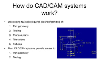
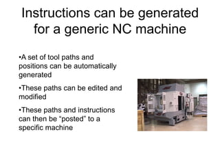
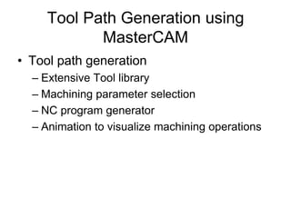
This document provides an introduction to CAD/CAM and MasterCAM software. It outlines the objectives of understanding CAD/CAM applications in lean manufacturing and learning how to create 2D geometries and toolpaths in MasterCAM. Key points covered include the use of CAD for design and CAM for manufacturing planning, how CAD/CAM systems work by developing NC code based on part geometry, tooling, and process plans, and exercises for discussing how CAD/CAM supports lean manufacturing and the advantages it provides for NC programming.


![Adding Arcs, Radius and Fillets
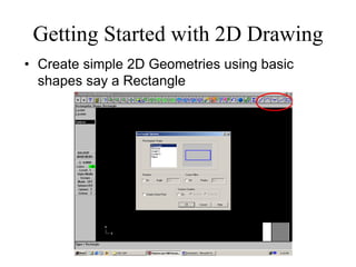
• Click on Main Menu [Create- Arc-pt dia cir] on to
dimension and place arcs/circles
• Click on Main Menu [Create-Fillets] to create Fillets.
Dimension them Suitably.](https://image.slidesharecdn.com/lecture-01-introduction-to-cadcam-221007025104-6d7de77e/85/Lecture-01-Introduction-to-CADCAM-pdf-21-320.jpg)
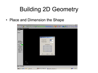
![Completing our Mock Profile
• To Trim or Cut entities Main Menu [Modify-Trim-2
Entities] to get required profile.
Don’t forget to Save your file](https://image.slidesharecdn.com/lecture-01-introduction-to-cadcam-221007025104-6d7de77e/85/Lecture-01-Introduction-to-CADCAM-pdf-22-320.jpg)
![Getting started with Toolpaths
• Click on Main Menu [Toolpaths]. MasterCAM lists
the different machining operations](https://image.slidesharecdn.com/lecture-01-introduction-to-cadcam-221007025104-6d7de77e/85/Lecture-01-Introduction-to-CADCAM-pdf-23-320.jpg)