Downloaded 309 times
![Wire V9 GENERAL NOTES
ASSIGNING BUTTONS AND KEYS
This Mastercam feature lets you assign a function or C-Hook or macro to a function key
(F1 through F10) or an Alt key (excluding system keys such as Alt+F4) or a button in
Mastercam's Toolbar. You can assign a maximum of 50 keys and a maximum of 99
buttons.
Select the following menu picks:
MAIN MENU
Screen
Configure
Toolbar/ Keys
Funcs/ C-Hooks/ Macros [default]
This allows the user to check all assignments, or filter out the desired
commands. ( Functions, c-hooks, macros, keys, buttons, keys/ buttons).
All [default]
This function allows the user to further filter using the following variables:
Unassigned, assigned, all.
Find Key
This function allows the user to press a button or key, and the function assigned
to it will be filtered out.
Current Assignment
Add This allows the user to add an assignment.
Edit This allows a user to edit an existing assignment.
Remove This allows the user to remove an assignment.
Page 10](https://image.slidesharecdn.com/master-cam-9-090805004820-phpapp01/75/Master-Cam-9-11-2048.jpg)


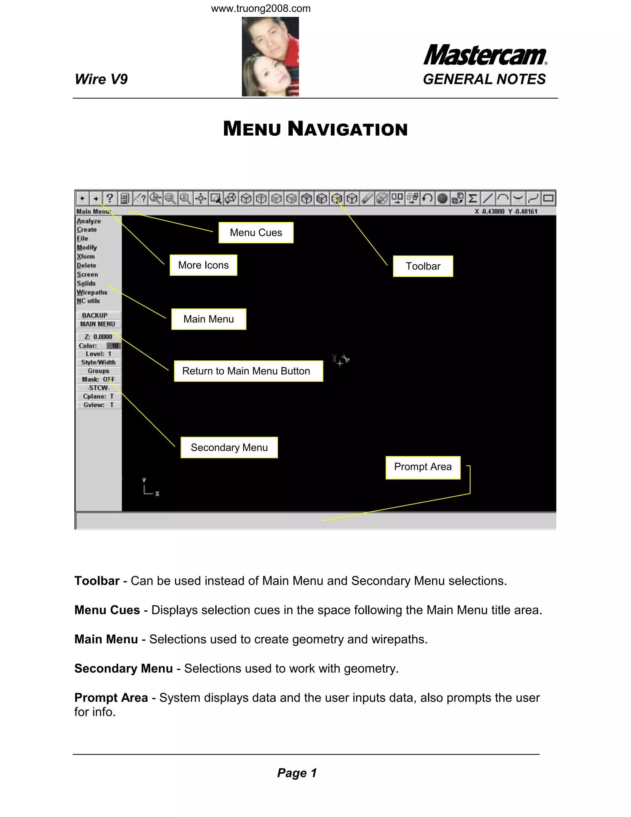
This document provides a 3-sentence summary of the Wire V9 tutorial: The tutorial covers the main menu, secondary menu, and other interface elements of Wire V9 such as toolbars, menus, and prompt areas for inputting data. It also describes functions for creating and modifying geometry, transforming objects, and programming wirepaths. Default key bindings are listed to navigate the interface and access common commands.


![Vibe Coding vs. Spec-Driven Development [Free Meetup]](https://cdn.slidesharecdn.com/ss_thumbnails/vibecodingvsspecdrivendevelopment-251209105622-43f455e7-thumbnail.jpg?width=640&height=640&fit=bounds)