CCS355 Neural Network & Deep Learning UNIT III notes and Question bank .pdf
summing amplifier.ppt
1. Presented by
Mr. SARAVANAN.R, M.E., Ph.D).,
Assistant Professor, Department of EEE,
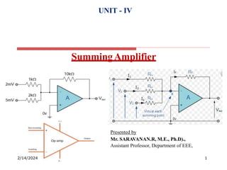
SummingAmplifier
UNIT - IV
2/14/2024 1
2. Summing Amplifier
The Summing Amplifier is another type of operational amplifier circuit
configuration that is used to combine the voltages present on two or more inputs into
a single output voltage.
We saw previously in the inverting operational amplifier that the inverting amplifier
has a single input voltage, (Vin) applied to the inverting input terminal. If we add
more input resistors to the input, each equal in value to the original input resistor,
(Rin) we end up with another operational amplifier circuit called a Summing
Amplifier, “summing inverter” or even a “voltage adder”.
2/14/2024 2
3. Contd..
Summing Amplifier Circuit
In this simple summing amplifier circuit, the output voltage, ( Vout ) now becomes
proportional to the sum of the input voltages, V1, V2, V3, etc. Then we can modify
the original equation for the inverting amplifier to take account of these new inputs
thus:
2/14/2024 3
4. Contd..
However, if all the input impedances, ( RIN ) are equal in value, we can simplify
the above equation to give an output voltage of:
SummingAmplifier Equation
2/14/2024 4
5. Contd..
2/14/2024 5
We now have an operational amplifier circuit that will amplify each individual
input voltage and produce an output voltage signal that is proportional to the
algebraic “SUM” of the three individual input voltages V1, V2 and V3. We can
also add more inputs if required as each individual input “sees” their respective
resistance, Rin as the only input impedance.
This is because the input signals are effectively isolated from each other by the
“virtual earth” node at the inverting input of the op-amp. A direct voltage
addition can also be obtained when all the resistances are of equal value and Rƒ
is equal to Rin.
Note that when the summing point is connected to the inverting input of the op-
amp the circuit will produce the negative sum of any number of input voltages.
Likewise, when the summing point is connected to the non-inverting input of
the op-amp, it will produce the positive sum of the input voltages.
6. Contd..
A Scaling Summing Amplifier can be made if the individual input resistors are
“NOT” equal. Then the equation would have to be modified to:
To make the math’s a little easier, we can rearrange the above formula to make
the feedback resistor Rƒ the subject of the equation giving the output voltage as:
This allows the output voltage to be easily calculated if more input resistors are
connected to the amplifiers inverting input terminal. The input impedance of
each individual channel is the value of their respective input resistors, ie, R1, R2,
R3 … etc.
2/14/2024 6
7. Contd..
The Summing Amplifier is a very flexible circuit indeed, enabling us to
effectively “Add” or “Sum” (hence its name) together several individual input
signals. If the inputs resistors, R1, R2, R3 etc, are all equal a “unity gain
inverting adder” will be made. However, if the input resistors are of different
values a “scaling summing amplifier” is produced which will output a weighted
sum of the input signals.
2/14/2024 7
8. Contd..
2/14/2024 8
Non-inverting Summing Amplifier
But as well as constructing inverting summing amplifiers, we can also use the non-
inverting input of the operational amplifier to produce a non-inverting summing
amplifier. We have seen above that an inverting summing amplifier produces the
negative sum of its input voltages then it follows that the non- inverting summing
amplifier configuration will produce the positive sum of its input voltages.
As its name implies, the non-inverting summing amplifier is based around the
configuration of a non-inverting operational amplifier circuit in that the input (either
ac or dc) is applied to the non-inverting (+) terminal, while the required negative
feedback and gain is achieved by feeding back some portion of the output signal
(VOUT) to the inverting (-) terminal as shown.