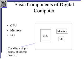
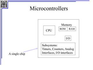
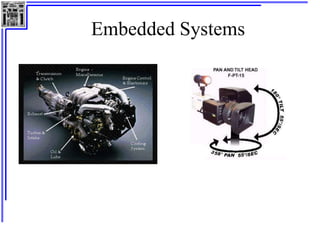
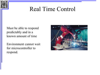
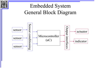
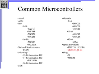
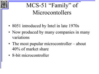
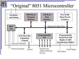
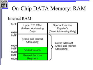
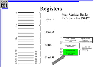
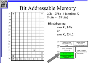
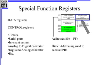
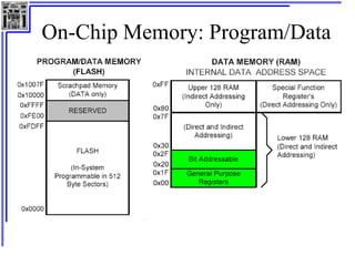
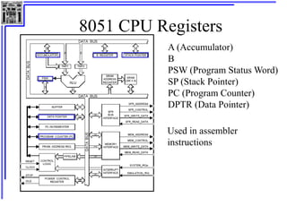
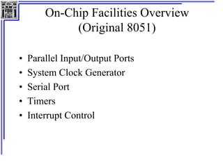
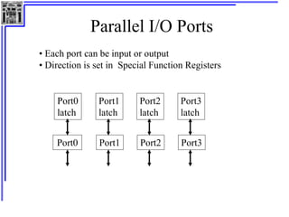
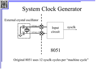
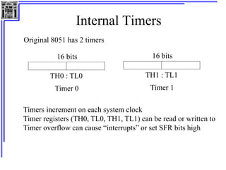
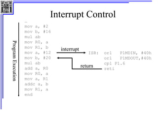
Microcontroller
Overview
• Basic components of digital computers
• Microcontrollers and Embedded Systems
• Applications and Common Microcontrollers
• MSP430 Family of Microcontrollers
• On-chip memory, registers
• On-chip facilities overview
Basic Components of Digital
Computer
• CPU
• Memory
• I/O CPU
Memory
I/O
Could be a chip, a
board, or several
boards
Microcontrollers
CPU
ROM RAM
I/O
A single chip
Subsystems:
Timers, Counters, Analog
Interfaces, I/O interfaces
Memory
Embedded Systems
Real Time Control
Must be able to respond
predictably and in a
known amount of time
Environment cannot wait
for microcontroller to
respond.
Embedded System
General Block Diagram
Microcontroller
(uC)
sensor
sensor
sensor
Sensor
conditioning
Output
interfaces
actuator
indicator
Common Microcontrollers
•Atmel
•ARM
•Intel
•8-bit
•8XC42
•MCS48
•MCS51
•8xC251
•16-bit
•MCS96
•MXS296
•National Semiconductor
•COP8
•Microchip
•12-bit instruction PIC
•14-bit instruction PIC
•PIC16F84
•16-bit instruction PIC
•NEC
•Motorola
•8-bit
•68HC05
•68HC08
•68HC11
•16-bit
•68HC12
•68HC16
•32-bit
•683xx
•Texas Instruments
•TMS370, 16/32 bit
•MSP430 , 16 bit
•Zilog
•Z8
•Z86E02
Microcontroller Architectures
CPU
Program
+ Data
Address Bus
Data Bus
Memory
Von Neumann
Architecture
CPU
Program
Address Bus
Data Bus
Harvard
Architecture
Memory
Data
Address Bus
Fetch Bus
0
0
0
2n
MCS-51 “Family” of
Microcontollers
• 8051 introduced by Intel in late 1970s
• Now produced by many companies in many
variations
• The most pupular microcontroller – about
40% of market share
• 8-bit microcontroller
“Original” 8051 Microcontroller
Oscillator
and timing
4096 Bytes
Program
Memory
128 Bytes
Data
Memory
Two 16 Bit
Timer/Event
Counters
8051
CPU
64 K Byte Bus
Expansion
Control
Programmable
I/O
Programmable
Serial Port Full
Duplex UART
Synchronous Shifter
Internal data bus
External interrupts
subsystem interrupts
Control Parallel ports
Address Data Bus
I/O pins
Serial Input
Serial Output
Review Binary/Hexidecimal
Decimal Binary Hexidecimal
0 0000 0
1 0001 1
2 0010 2
3 0011 3
4 0100 4
5 0101 5
6 0110 6
7 0111 7
8 1000 8
9 1001 9
10 1010 A
11 1011 B
12 1100 C
13 1101 D
14 1110 E
15 1111 F
Conversions:
1000 1110 (binary)
8 E (hex)
Notations for hex:
0x8E
8Eh
8E16
On-Chip DATA Memory: RAM
Internal RAM
Registers
07
06
05
04
03
02
01
00
R7
R6
R5
R4
R3
R2
R1
R0
0F
08
17
10
1F
18
Bank 3
Bank 2
Bank 1
Bank 0
Four Register Banks
Each bank has R0-R7
Bit Addressable Memory
20h – 2Fh (16 locations X
8-bits = 128 bits)
7F 78
1A
10
0F 08
07 06 05 04 03 02 01 00
27
26
25
24
23
22
21
20
2F
2E
2D
2C
2B
2A
29
28
Bit addressing:
mov C, 1Ah
or
mov C, 23h.2
Special Function Registers
DATA registers
CONTROL registers
•Timers
•Serial ports
•Interrupt system
•Analog to Digital converter
•Digital to Analog converter
•Etc.
Addresses 80h – FFh
Direct Addressing used to
access SPRs
On-Chip Memory: Program/Data
8051 CPU Registers
A (Accumulator)
B
PSW (Program Status Word)
SP (Stack Pointer)
PC (Program Counter)
DPTR (Data Pointer)
Used in assembler
instructions
On-Chip Facilities Overview
(Original 8051)
• Parallel Input/Output Ports
• System Clock Generator
• Serial Port
• Timers
• Interrupt Control
Parallel I/O Ports
Port0
latch
Port1
latch
Port2
latch
Port3
latch
Port0 Port1 Port2 Port3
• Each port can be input or output
• Direction is set in Special Function Registers
System Clock Generator
Input
circuit
8051
sysclk
Original 8051 uses 12 sysclk cycles per “machine cycle”
External crystal oscillator
Serial Port (UART)
Serial
Port
TX (transmit)
RX (receive)
Data sent and received serially
BAUD rate must agree between sender and receiver
Transmission modes selected using SFR
Original 8051 had one serial port
Internal Timers
Original 8051 has 2 timers
16 bits
TH0 : TL0
Timer 0
16 bits
TH1 : TL1
Timer 1
Timers increment on each system clock
Timer registers (TH0, TL0, TH1, TL1) can be read or written to
Timer overflow can cause “interrupts” or set SFR bits high
Interrupt Control
…
mov a, #2
mov b, #16
mul ab
mov R0, a
mov R1, b
mov a, #12
mov b, #20
mul ab
add a, R0
mov R0, a
mov a, R1
addc a, b
mov R1, a
end
Program
Execution
interrupt
ISR: orl P1MDIN, #40h
orl P1MDOUT,#40h
cpl P1.6
reti
return
Interrupt Control
Original 8051 has five sources of interrupts
• Timer 1 overflow
• Timer 2 overflow
• External Interrupt 0
• External Interrupt 1
• Serial Port events (buffer full, buffee empty, etc)
Interrupts enabled and disabled using SFR

Microprocessors and Microcontrollers.ppt