State estimation power point presentation in Unit V
1.
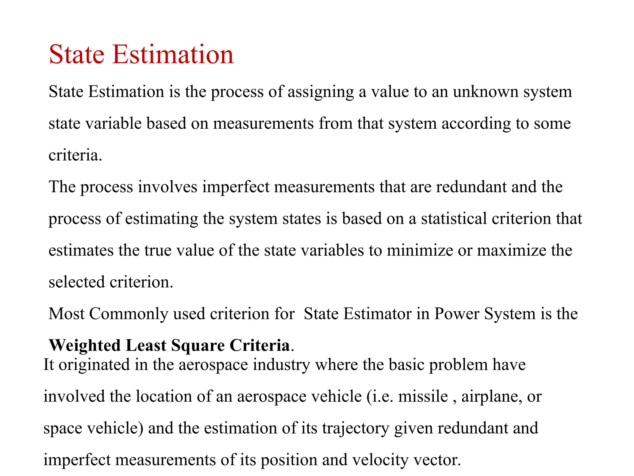
State Estimation
State Estimationis the process of assigning a value to an unknown system
state variable based on measurements from that system according to some
criteria.
The process involves imperfect measurements that are redundant and the
process of estimating the system states is based on a statistical criterion that
estimates the true value of the state variables to minimize or maximize the
selected criterion.
Most Commonly used criterion for State Estimator in Power System is the
Weighted Least Square Criteria.
It originated in the aerospace industry where the basic problem have
involved the location of an aerospace vehicle (i.e. missile , airplane, or
space vehicle) and the estimation of its trajectory given redundant and
imperfect measurements of its position and velocity vector.
2.
In many applications,these measurements are based on optical
observations and/or radar signals that may be contaminated with
noise and may contain system measurement errors.
In the Power System, The State Variables are the voltage
Magnitudes and Relative Phase Angles at the System Nodes.
The inputs to an estimator are imperfect power system
measurements of voltage magnitude and power, VAR, or ampere
flow quantities.
The Estimator is designed to produce the “best estimate” of the
system voltage and phase angles, recognizing that there are
errors in the measured quantities and that they may be redundant
measurements.
3.
SE Measurement Types
WhatMeasurements Can Be Used?
Bus voltage magnitudes.
Real, reactive and ampere injections.
Real, reactive and ampere branch flows.
Bus voltage magnitude and angle differences.
Transformer tap/phase settings.
Sums of real and reactive power flows.
Real and reactive zone interchanges.
Unpaired measurements ok
4.
04/21/25 Power SystemOperation and Control 4
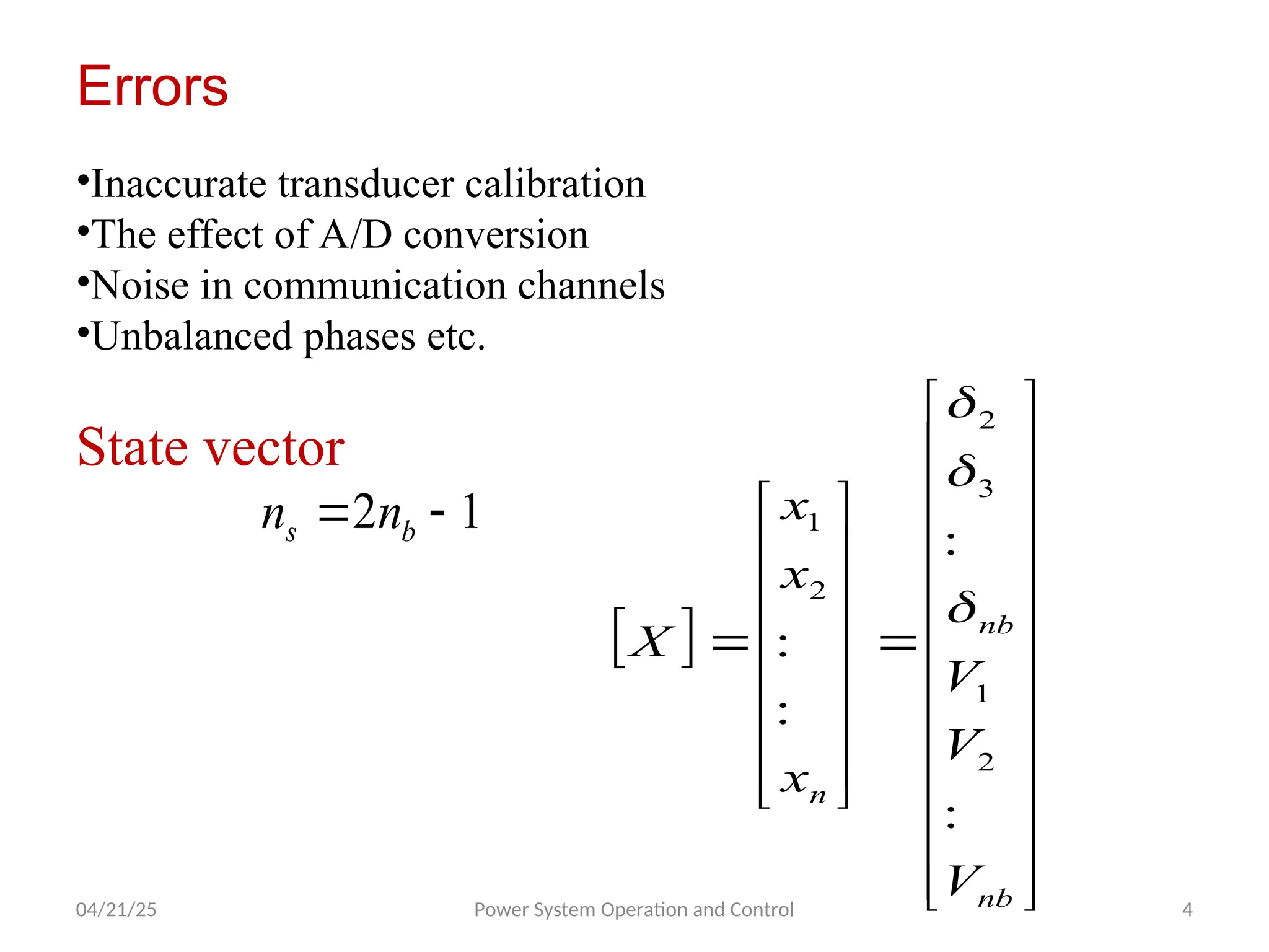
Errors
•Inaccurate transducer calibration
•The effect of A/D conversion
•Noise in communication channels
•Unbalanced phases etc.
State vector
1
2
b
s n
n
nb
nb
n
V
V
V
x
x
x
X
:
:
:
:
2
1
3
2
2
1
5.
04/21/25 Power SystemOperation and Control 5
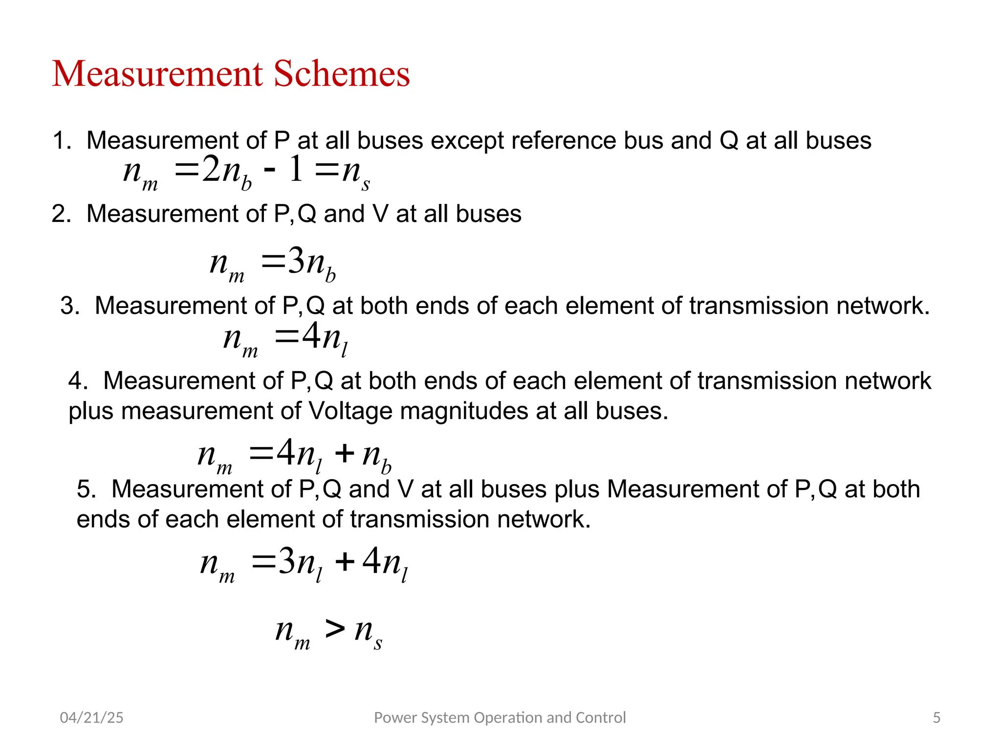
Measurement Schemes
1. Measurement of P at all buses except reference bus and Q at all buses
s
b
m n
n
n
1
2
2. Measurement of P,Q and V at all buses
b
m n
n 3
3. Measurement of P,Q at both ends of each element of transmission network.
l
m n
n 4
4. Measurement of P,Q at both ends of each element of transmission network
plus measurement of Voltage magnitudes at all buses.
b
l
m n
n
n
4
5. Measurement of P,Q and V at all buses plus Measurement of P,Q at both
ends of each element of transmission network.
l
l
m n
n
n 4
3
s
m n
n
6.
04/21/25 Power SystemOperation and Control 6
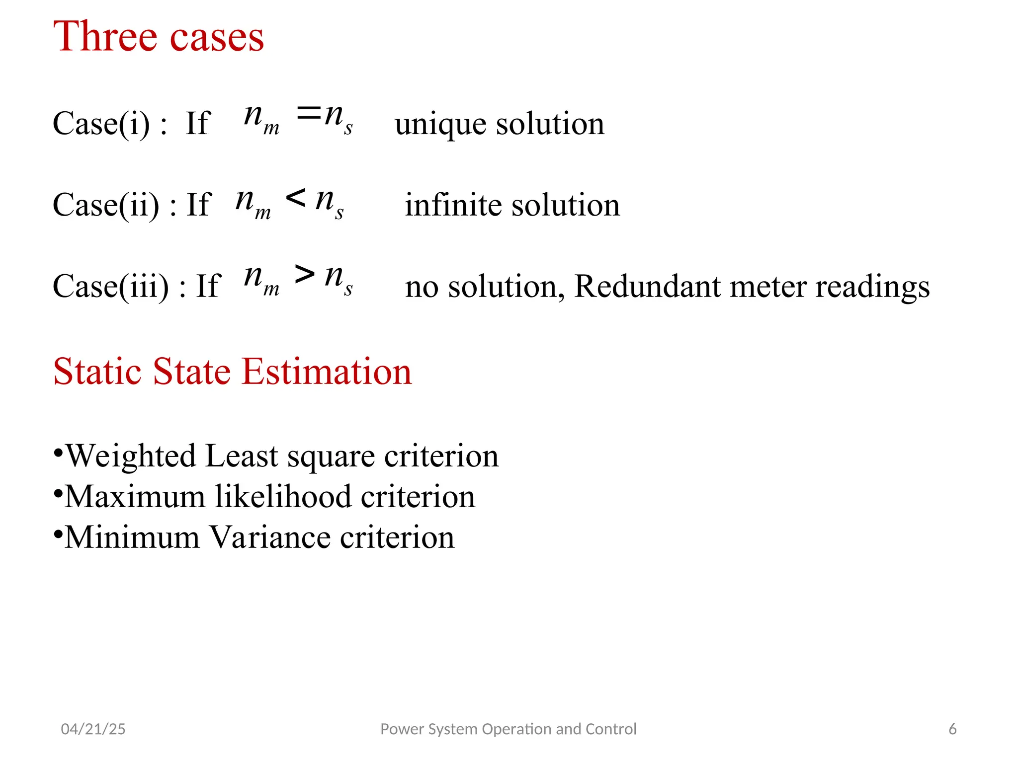
Three cases
Case(i) : If unique solution
Case(ii) : If infinite solution
Case(iii) : If no solution, Redundant meter readings
Static State Estimation
•Weighted Least square criterion
•Maximum likelihood criterion
•Minimum Variance criterion
s
m n
n
s
m n
n
s
m n
n
7.
04/21/25 Power SystemOperation and Control 7
Weighted Least square Estimation
•Estimate the current state from last known values of state vector.
]}
[
]
[
]{
[
]}
[
]
[
{
, Z
x
F
W
Z
X
F
J
unction
objectivef T
2
1
]}
[
]
[
{
, i
i
n
i
i Z
X
F
W
J
Expanding
s
]
[
]
[
0 i
i Z
X
whenF
J
]
][
[
]
[
])
[
]
([
]
[ 0
0 X
A
X
F
X
X
F
X
F
]}
[
]
][
[
]
[
]{
[
]}
[
]
][
[
]
[
{ 0
0 Z
X
A
X
F
W
Z
X
A
X
F
J T
]}
][
[
]
[
]
[
]{
[
]}
][
[
]
[
]
[
{ 0
0 X
A
Z
X
F
W
X
A
Z
X
F
J T
]}
[
]
[
]{
[
]
[
]
[
2
]
][
][
[
]
[
]}
[
]}
[
]
[
]{
[
]}
[
]
[
{
0
0
0
Z
X
F
W
X
A
X
A
W
A
X
Z
X
F
W
Z
X
F
J
T
T
T
T
T
8.
04/21/25 Power SystemOperation and Control 8
0
|
]
ˆ
[
]
[
]
[
X
X
X
J
0
]}
[
]
[
]{
[
]
[
2
]
ˆ
][
[
]
[
2
]
[
0
Z
X
F
W
A
X
W
A
X
J T
T
]}
[
]
[
]{
[
]
[
2
]
ˆ
][
[
]
[
2 0 Z
X
F
W
A
X
W
A T
T
]}
[
]
[
]{
[
]
[
]}
][
[
]
{[
]
ˆ
[ 0
1
Z
X
F
W
A
A
W
A
X T
T
]
[
]
[
]}
[
]
]{[
[
]
[
]}
][
[
]
{[
]
ˆ
[
0
0
1
X
X
where
X
F
Z
W
A
A
W
A
X T
T
9.
04/21/25 Power SystemOperation and Control 9
Algorithm
•Calculate and corresponding to
•Calculate
•If is small, then stop and
•If is not small, then update
]
[X
F
X
F
A
]
[ ]
[ 0
X
]
ˆ
[ X
]
ˆ
[ X
]
ˆ
[
]
[ 0 X
X
]
ˆ
[ X
0
X
]
ˆ
[
]
[
]
[ 0
0 X
X
X old
new
and go to step 1.
10.
04/21/25 Power SystemOperation and Control 10
1
1
1
1
]
[
],
[
]}
[
]
{[
]
[
]
[
]}
[
]
[
]
{[
]
ˆ
[
C
use
W
insteadof
X
F
Z
C
A
A
C
A
X T
T
11.
04/21/25 Power SystemOperation and Control 11
Treatment of bad data or Error identification
Case(i) : If unique solution
Case(ii) : If redundancy exists.
So J=0
Case(iii) : If bad measurements.
Detection of bad measurements with Deterministic State
Estimation
s
m n
n
s
m n
n 0
]
ˆ
[
X
s
m n
n 0
J
m
n
n
i
i
T
e E
W
E
W
E
J
unction
objectivef
1
2
]
][
[
]
[
,
m
n
i
i
i
i Z
X
F
W
J
Calculate
1
]}
[
]
[
]{
[
]
ˆ
[
12.
04/21/25 Power SystemOperation and Control 12
Case(i) : If no bad measurements
Case(ii) : If few bad measurements
Case(iii) : If accept the tolerance
Identification of bad measurements with Deterministic
State Estimation
Evaluate corresponding to the
estimated state for each measurement.
If more bad measurements eliminate
Repeat state estimation until
e
J
J
ˆ
e
J
J
ˆ
e
J
J
ˆ
m
n
i
i
i
i Z
X
F
W
J
1
2
]}
[
]
[
]{
[
]
ˆ
[X
e
J
J
ˆ
e
J
J
ˆ
13.
04/21/25 Power SystemOperation and Control 13
Detection of bad measurements with Probabilistic State
Estimation
Choose a suitable value of , then determine from
standard table.
k
J
]}
[
]
[
{
]
[
]}
[
]
[
{
]
ˆ
[ 1
Z
X
F
C
Z
X
F
J T
k
J
J
ˆ
If bad measurements identify bad data
Pseudo measurements )
( s
m n
n
1. Replace by alternate value
2. No program or algorithm change
3. Not good
14.
04/21/25 Power SystemOperation and Control 14
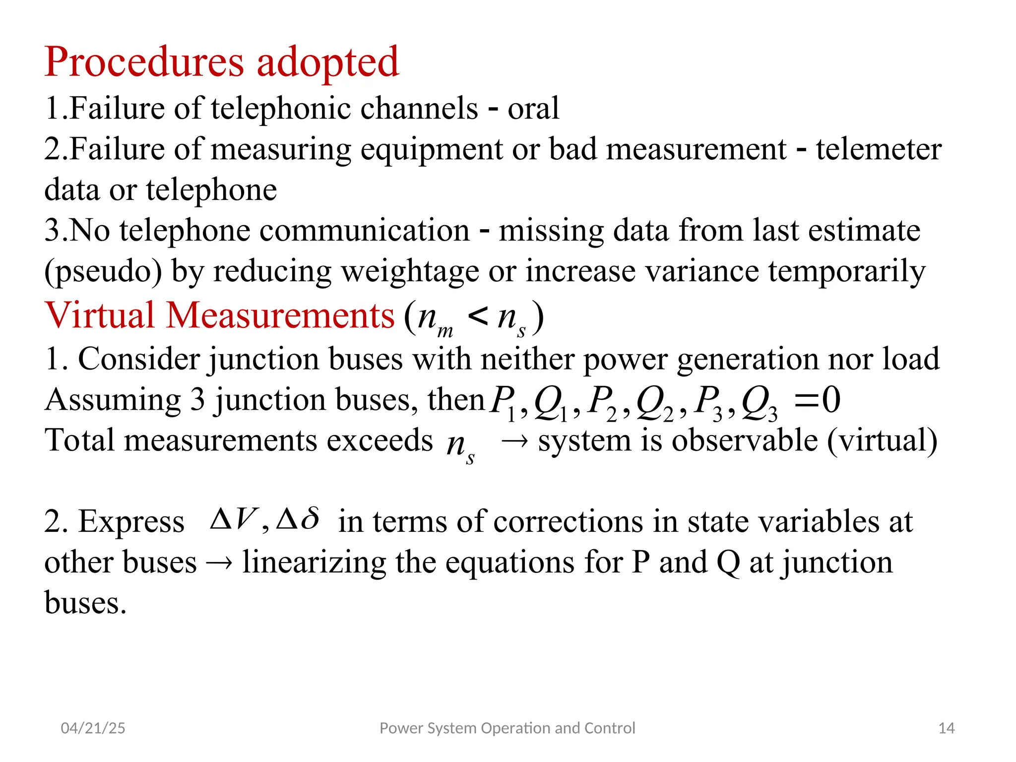
Procedures adopted
1.Failure of telephonic channels oral
2.Failure of measuring equipment or bad measurement telemeter
data or telephone
3.No telephone communication missing data from last estimate
(pseudo) by reducing weightage or increase variance temporarily
Virtual Measurements
1. Consider junction buses with neither power generation nor load
Assuming 3 junction buses, then
Total measurements exceeds system is observable (virtual)
2. Express in terms of corrections in state variables at
other buses linearizing the equations for P and Q at junction
buses.
)
( s
m n
n
0
,
,
,
,
, 3
3
2
2
1
1
Q
P
Q
P
Q
P
s
n
,
V
15.
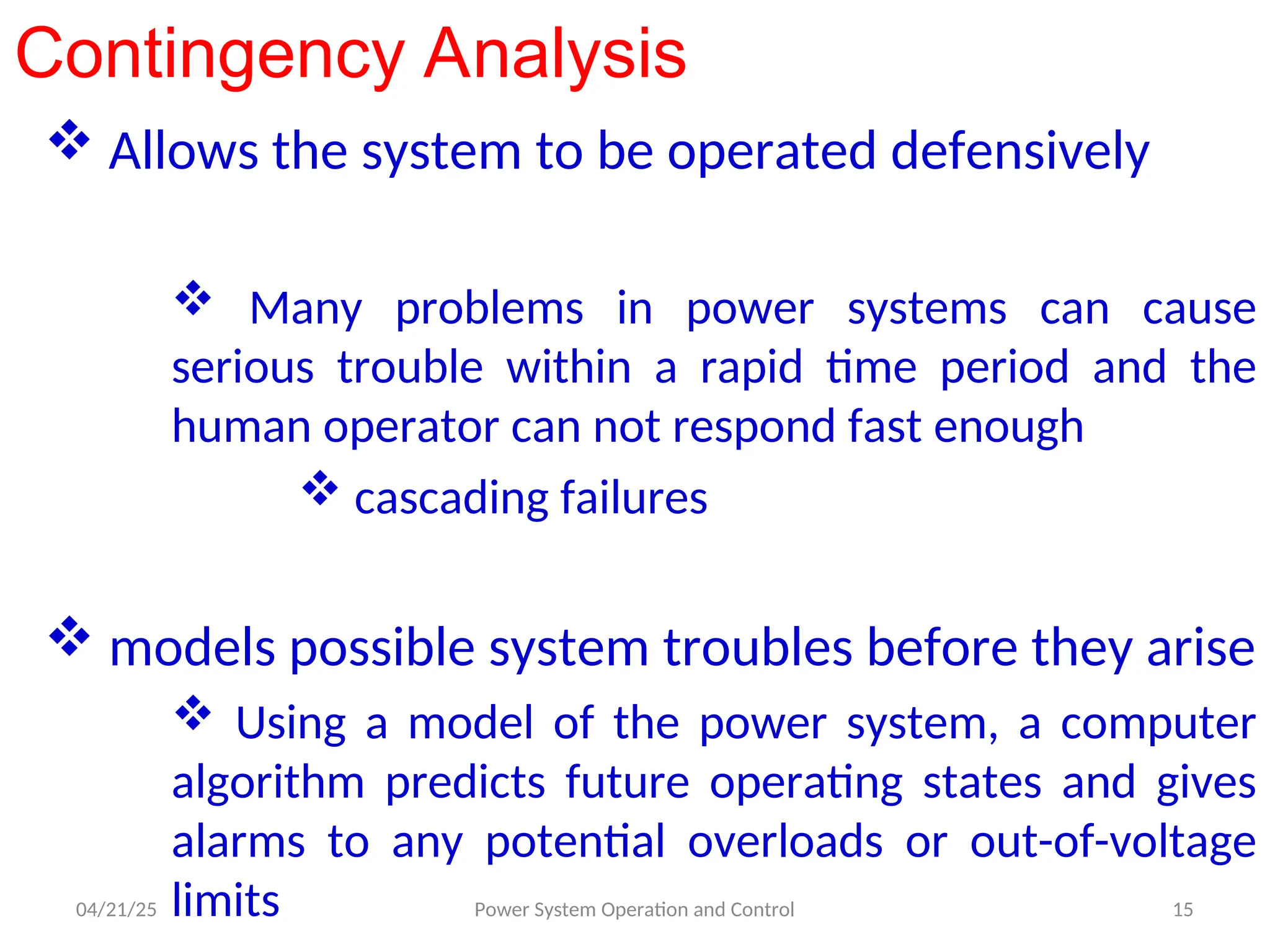
Contingency Analysis
Allowsthe system to be operated defensively
Many problems in power systems can cause
serious trouble within a rapid time period and the
human operator can not respond fast enough
cascading failures
models possible system troubles before they arise
Using a model of the power system, a computer
algorithm predicts future operating states and gives
alarms to any potential overloads or out-of-voltage
limits
04/21/25 15
Power System Operation and Control
![04/21/25 Power System Operation and Control 7
Weighted Least square Estimation
•Estimate the current state from last known values of state vector.
]}
[
]
[
]{
[
]}
[
]
[
{
, Z
x
F
W
Z
X
F
J
unction
objectivef T
2
1
]}
[
]
[
{
, i
i
n
i
i Z
X
F
W
J
Expanding
s
]
[
]
[
0 i
i Z
X
whenF
J
]
][
[
]
[
])
[
]
([
]
[ 0
0 X
A
X
F
X
X
F
X
F
]}
[
]
][
[
]
[
]{
[
]}
[
]
][
[
]
[
{ 0
0 Z
X
A
X
F
W
Z
X
A
X
F
J T
]}
][
[
]
[
]
[
]{
[
]}
][
[
]
[
]
[
{ 0
0 X
A
Z
X
F
W
X
A
Z
X
F
J T
]}
[
]
[
]{
[
]
[
]
[
2
]
][
][
[
]
[
]}
[
]}
[
]
[
]{
[
]}
[
]
[
{
0
0
0
Z
X
F
W
X
A
X
A
W
A
X
Z
X
F
W
Z
X
F
J
T
T
T
T
T
](https://image.slidesharecdn.com/cc1-250421042209-64273127/75/State-estimation-power-point-presentation-in-Unit-V-7-2048.jpg)
![04/21/25 Power System Operation and Control 8
0
|
]
ˆ
[
]
[
]
[
X
X
X
J
0
]}
[
]
[
]{
[
]
[
2
]
ˆ
][
[
]
[
2
]
[
0
Z
X
F
W
A
X
W
A
X
J T
T
]}
[
]
[
]{
[
]
[
2
]
ˆ
][
[
]
[
2 0 Z
X
F
W
A
X
W
A T
T
]}
[
]
[
]{
[
]
[
]}
][
[
]
{[
]
ˆ
[ 0
1
Z
X
F
W
A
A
W
A
X T
T
]
[
]
[
]}
[
]
]{[
[
]
[
]}
][
[
]
{[
]
ˆ
[
0
0
1
X
X
where
X
F
Z
W
A
A
W
A
X T
T
](https://image.slidesharecdn.com/cc1-250421042209-64273127/75/State-estimation-power-point-presentation-in-Unit-V-8-2048.jpg)
![04/21/25 Power System Operation and Control 9
Algorithm
•Calculate and corresponding to
•Calculate
•If is small, then stop and
•If is not small, then update
]
[X
F
X
F
A
]
[ ]
[ 0
X
]
ˆ
[ X
]
ˆ
[ X
]
ˆ
[
]
[ 0 X
X
]
ˆ
[ X
0
X
]
ˆ
[
]
[
]
[ 0
0 X
X
X old
new
and go to step 1.](https://image.slidesharecdn.com/cc1-250421042209-64273127/75/State-estimation-power-point-presentation-in-Unit-V-9-2048.jpg)
![04/21/25 Power System Operation and Control 10
1
1
1
1
]
[
],
[
]}
[
]
{[
]
[
]
[
]}
[
]
[
]
{[
]
ˆ
[
C
use
W
insteadof
X
F
Z
C
A
A
C
A
X T
T](https://image.slidesharecdn.com/cc1-250421042209-64273127/75/State-estimation-power-point-presentation-in-Unit-V-10-2048.jpg)
![04/21/25 Power System Operation and Control 11
Treatment of bad data or Error identification
Case(i) : If unique solution
Case(ii) : If redundancy exists.
So J=0
Case(iii) : If bad measurements.
Detection of bad measurements with Deterministic State
Estimation
s
m n
n
s
m n
n 0
]
ˆ
[
X
s
m n
n 0
J
m
n
n
i
i
T
e E
W
E
W
E
J
unction
objectivef
1
2
]
][
[
]
[
,
m
n
i
i
i
i Z
X
F
W
J
Calculate
1
]}
[
]
[
]{
[
]
ˆ
[](https://image.slidesharecdn.com/cc1-250421042209-64273127/75/State-estimation-power-point-presentation-in-Unit-V-11-2048.jpg)
![04/21/25 Power System Operation and Control 12
Case(i) : If no bad measurements
Case(ii) : If few bad measurements
Case(iii) : If accept the tolerance
Identification of bad measurements with Deterministic
State Estimation
Evaluate corresponding to the
estimated state for each measurement.
If more bad measurements eliminate
Repeat state estimation until
e
J
J
ˆ
e
J
J
ˆ
e
J
J
ˆ
m
n
i
i
i
i Z
X
F
W
J
1
2
]}
[
]
[
]{
[
]
ˆ
[X
e
J
J
ˆ
e
J
J
ˆ](https://image.slidesharecdn.com/cc1-250421042209-64273127/75/State-estimation-power-point-presentation-in-Unit-V-12-2048.jpg)
![04/21/25 Power System Operation and Control 13
Detection of bad measurements with Probabilistic State
Estimation
Choose a suitable value of , then determine from
standard table.
k
J
]}
[
]
[
{
]
[
]}
[
]
[
{
]
ˆ
[ 1
Z
X
F
C
Z
X
F
J T
k
J
J
ˆ
If bad measurements identify bad data
Pseudo measurements )
( s
m n
n
1. Replace by alternate value
2. No program or algorithm change
3. Not good](https://image.slidesharecdn.com/cc1-250421042209-64273127/75/State-estimation-power-point-presentation-in-Unit-V-13-2048.jpg)