The paper presents a source-load-variable voltage regulated cascaded dc/dc converter aimed at achieving stable output voltage in dc microgrid systems, particularly with solar energy sources. It reports a regulated output of 203.1 V dc with minimal fluctuations despite variations in input voltage and load resistance, achieved through a simulation model. This converter utilizes a voltage lift technique and operates at a lower duty ratio to minimize switching losses, making it suitable for applications like battery charging.
![International Journal of Electrical and Computer Engineering (IJECE)
Vol. 13, No. 1, February 2023, pp. 107~115
ISSN: 2088-8708, DOI: 10.11591/ijece.v13i1.pp107-115 107
Journal homepage: http://ijece.iaescore.com
Source-load-variable voltage regulated cascaded DC/DC
converter for a DC microgrid system
Radhika Salyam, Vijaya Margaret
Department of Electrical and Electronics Engineering, School of Engineering and Technology, Christ University, Bengaluru, India
Article Info ABSTRACT
Article history:
Received Apr 12, 2022
Revised Aug 1, 2022
Accepted Aug 19, 2022
Solar energy is available abundantly, the utilization of solar energy is
developing rapidly and the photovoltaic based direct current (DC) microgrid
system design is under demand but the stability of the DC voltage is of most
important issue, as the variation of the output DC voltage is a common
problem when the load or source voltage varies, hence a regulated DC
output voltage converter is proposed. This paper presents source-load-
variable (SLV) voltage regulated cascaded DC/DC converter which is used
to obtain regulated output voltage of 203.1 V DC at 0.4 duty ratio with ±2%
voltage fluctuations for the variation in the input source voltage and ±1.5%
voltage fluctuations for the variation in load resistance of the nominal value
with lower output voltage ripple and without use of sub circuits. A
simulation model of SLV voltage regulated cascaded DC/DC converter in
LTspice XVII software environment for the assessment of converter
performance at different input source voltages and load resistances are
verified.
Keywords:
DC microgrid
DC/DC converter
Photovoltaic system
Voltage lift technique
Voltage regulation
This is an open access article under the CC BY-SA license.
Corresponding Author:
Radhika Salyam
Department of Electrical and Electronics Engineering, School of Engineering and Technology,
Christ University
Bengaluru, India
Email: radhika.s@res.christuniversity.in
NOMENCLATURE
CIBC - Cascaded interleaved boost converter PC - Proposed converter
VIN - DC input source voltage Vin1 - DC input source voltage of 22V
VO1 - DC output voltage of stage1 at C5 Vin2 - DC input source voltage at stage2
VO2 - DC regulated output voltage at C6 VC1 - Voltage across capacitor C1
VC2 - Voltage across capacitor C2 VC3 - Voltage across capacitor C3
VC4 - Voltage across capacitor C4 VC5 - Voltage across capacitor C5
VC6 - Voltage across capacitor C6 VL1 - Voltage across inductor L1
VL2 - Voltage across inductor L2 VL3 - Voltage across inductor L3
VL4 - Voltage across inductor L4 VL5 - Voltage across inductor L5
VL6 - Voltage across inductor L6 VOUT - Regulated output voltage
∗ Off state value of each component D - Duty ratio of switches = 0.4
1. INTRODUCTION
In current years, direct current (DC) microgrids are increasing rapidly in electric power grids and
other isolated systems, storage units, DC loads and renewable energy resources [1]. A DC microgrid is](https://image.slidesharecdn.com/v1128117emr1aug2212apr22nn-221118060808-72d543b6/75/Source-load-variable-voltage-regulated-cascaded-DC-DC-converter-for-a-DC-microgrid-system-1-2048.jpg)
![ ISSN: 2088-8708
Int J Elec & Comp Eng, Vol. 13, No. 1, February 2023: 107-115
108
essential for an unconventional control system and in the main grid when error occurs it is best to work in an
islanded method. There are a large number of advantages by using photovoltaic (PV) systems when
compared to other renewable energy resources [2] but as solar energy is intermittent energy, regulated output
is necessary for stable operation of the microgrids. Solar energy production industries have increased to
150 GW from 21 GW between 2010 to 2020 [3], [4]. In the year 2020, in spite of the coronavirus disease
(COVID-19) pandemic, reports in the worldwide renewable energy sources, there was an increase in
investment by 2% [5] and also show that new solar capacity reserves have improved by 12% and reached
USD 148.6 billion. The initial data displays that the new PV capacity has increased by almost 20% which is
nearly 140 GW [6], [7]. In India new installations dropped during this period from stronger marketing in
2019 [8]. There are more possibilities of reduction in the cost which will drive the development of PV
installations in the coming decades. In 2022, higher progress rate is expected according to most of the market
estimates along with new installations and also breaking 1 TW barrier [9].
There is a necessity for incorporating the system into the DC microgrid to enhance the power
management, stability and consistency in the power distribution system. When the alternating current (AC)
system is compared with DC microgrid, it gives the option of improved efficient integration for any
residential renewable energy source and the storage battery systems [10]. DC microgrids are dominant in
consistency, efficiency and control systems but the power quality issues and voltage levels in the DC
microgrid system have to be handled accurately. It is easier for the integration of the DC source renewable
generation with the energy storage system in a DC microgrid system [11]. In DC microgrids unlike in AC
microgrids, the difficulties like synchronization, phase unbalanced and harmonics do not occur. Hence, there
is a large growth in the usage of DC sources in commercial, residential and industrial systems [12]–[15].
A DC microgrid configuration is as shown in Figure 1. It consists of a PV panel, battery storage
system, DC microgrid, DC/DC converters and DC loads. A DC/DC boost converter is used between the PV
panel and the DC bus to step up the voltage to the required level and the battery is connected to the DC bus
through a bidirectional buck-boost DC/DC converter and finally, the loads are connected to a DC bus through
the buck DC/DC converter. The DC microgrid system, due to the nature of the DC/DC converters, PV system
and the load is basically a nonlinear system. The International Space Station is a standard example of a DC
microgrid. When the solar rays in connection with illumination deliver power to the loads and batteries, the
batteries discharge if the solar arrays cannot generate enough power to the loads in order to supply the
remaining power. To regulate voltage, DC/DC converters are being used [16]. In recent years, various
researchers have contributed their works in the DC microgrid system mainly consisting of photovoltaic
systems particularly concentrating on the energy management, stability issues and control system techniques.
In various control strategies, DC bus voltage controlling in a proper manner is an important controlling issue.
In this paper a new modest method named, source-load-variable (SLV) voltage regulated cascaded DC/DC
converter is being proposed to regulate the output voltage with minimum voltage fluctuations.
Figure 1. A DC microgrid system configuration](https://image.slidesharecdn.com/v1128117emr1aug2212apr22nn-221118060808-72d543b6/75/Source-load-variable-voltage-regulated-cascaded-DC-DC-converter-for-a-DC-microgrid-system-2-2048.jpg)
![Int J Elec & Comp Eng ISSN: 2088-8708
Source-load-variable voltage regulated cascaded DC/DC converter for a DC … (Radhika Salyam)
109
This paper is structured as: discussion about conventional circuits and the proposed method in
section 2, section 3 presents details of proposed converter with mathematical model. Then, discussion on the
simulation results of voltage regulated which validates theoretical results is described in section 4 along with
the simulation graphs of converter DC output voltage for variation in input source voltage and load
resistance. Discussion on assessment of operation of the performance of the proposed and cascaded interleaved
boost converter along with PV converter in section 5 and finally, overall work conclusion in section 6.
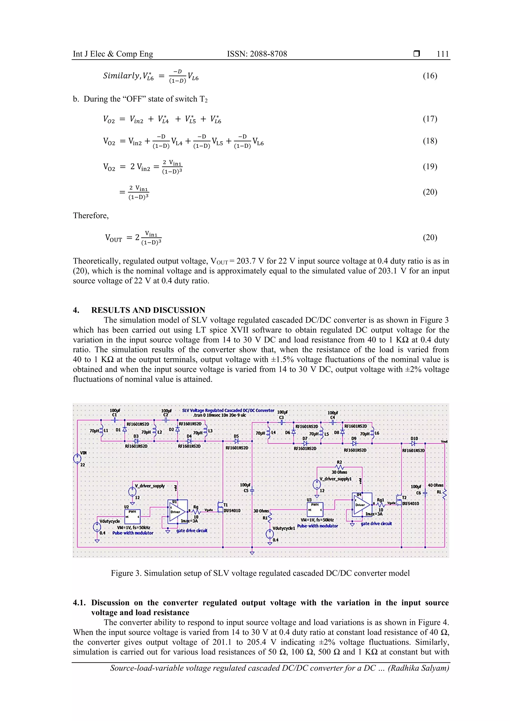
2. PROPOSED METHOD
In a conventional proportional integral controller (PI), the performance is affected by the load
variations when connected to DC microgrids, hence a feed forward control method has been studied by
considering the mismatched power/current disturbances to obtain an enhanced dynamic performance of the
dc link voltage to handle this difficulty. The main aim was to regulate the dc link voltage to a constant value
[17]–[19]. To have more reliable and comprehensive operation of the system, various refined control
schemes and energy management systems are being proposed and to maintain constant voltage at DC bus
which was based on comprehensive control system and the power management system, a nonlinear adaptive
backstepping controller design was being used which was a method for stabilizing DC bus voltage and it also
implemented flexibly in the power flow of the system [20]. In order to obtain the steady operation of a DC
microgrid, voltage regulators and load sharing controllers are the main requirements. To improve the stability
and for proper control of the load sharing, a primary controller with droop control method was being used in
the DC microgrid system but there was poor voltage regulation and load sharing in the system [21]–[23]. The
review of different methods proposed in the recent literature confirmed that to develop voltage regulated
DC/DC converters there are a number of techniques that are being proposed with various additional sub
circuit requirements like proportional integral derivative controllers (PID), droop control methods, and
feedback passivation method with high system complexity and poor voltage regulation.
The proposed, SLV voltage regulated cascaded DC/DC converter using voltage lift method with the
gate control circuit aims to attain regulated output voltage at lower duty ratio with minimum voltage
fluctuations with lower switching losses and without use of sub circuits. This system is suitable for
applications like battery charging and interconnecting to DC microgrids. The highlights of this converter are:
i) the application of voltage lift technique, ii) the operation of the converter at a lower duty cycle for
minimization of switching losses, and iii) regulated output voltage with minimum voltage fluctuations.
3. METHOD
This paper is an extension work of [24], which gives the operation of the circuit comprising of
inductors of 70 µH and capacitors of 100 µF which is the modified double voltage lift converter designed
with the arrangement of voltage lift technique and the boost circuit that results in obtaining enhanced output
voltage from the fixed input source voltage of 15 V DC at lower duty ratio varying from 0.4 to 0.6 which was
the preferred duty ratio of the converter. The inductors are represented with a dot notation pattern to
comprehend the flow of current in the circuit. The SLV voltage regulated cascaded DC/DC converter circuit
is as shown in Figure 2. The circuit operates based on the switches being in the “ON” and “OFF” states. The
inductors act as charging in parallel in the “ON” state and inductors discharge in series in the “OFF” state,
hence the output voltage can be enhanced as the inductor voltage gets added up. When the input source
voltage is varied between 14 to 30 V DC, the regulated output voltage is obtained which is constant at
203.1 V DC with ±2% voltage fluctuations and also when the load resistance is varied between 40 to 1 KΩ,
the output voltage is regulated at 203.1 V DC with ±1.5% voltage fluctuations at a switching frequency of
50 KHz with the gate control circuit comprising of the PWM signals in order to drive the switches to “ON”
state and “OFF” state at a lower duty ratio of 0.4. The control technique is based on the gate control circuit
consisting of the driver circuit and the PWM circuit which regulates the voltage in the converter to the
nominal value with minimum voltage fluctuations for the variations in the input source voltage and load. The
load resistance is varied to justify that constant power load can be attained as the output voltage is regulated
with slight variation in the output current of the converter.
3.1. Operation of switch T1
The SLV voltage regulated cascaded DC/DC converter is cascaded with two stages, the operation of
the converter is according to the “ON” and “OFF” states of the switches T1 and T2. When the switch T1 is
“ON”, the inductors are in a charging state which is indicated by the (1) to (3). As the inductor voltage is
equal to the product of D/(1–D) and “ON” state value [25], the capacitor and inductor voltages are as in (4) to
(6). When the switch T1 is “OFF”, the inductors are in discharging state and hence voltage enhances as in (7).
Finally, the output of stage 1 of the converter is as in (9).](https://image.slidesharecdn.com/v1128117emr1aug2212apr22nn-221118060808-72d543b6/75/Source-load-variable-voltage-regulated-cascaded-DC-DC-converter-for-a-DC-microgrid-system-3-2048.jpg)
![ ISSN: 2088-8708
Int J Elec & Comp Eng, Vol. 13, No. 1, February 2023: 107-115
110
Figure 2. SLV voltage regulated cascaded DC/DC converter [24]
a. During the “ON” state of switch T1
−𝑉𝐿1 = 𝑉𝑖𝑛1 (1)
−𝑉𝐿2 = 𝑉𝑖𝑛1 + 𝑉𝐶1 (2)
−𝑉𝐿3 = 𝑉𝑖𝑛1 + 𝑉𝐶1 + 𝑉𝐶2 (3)
𝑉𝐶1 = 𝑉𝐶1
∗
= 𝑉𝐿1
∗
=
−𝐷
(1−𝐷)
𝑉𝐿1 (4)
𝑉𝐶2 = 𝑉𝐶2
∗
= 𝑉𝐿2
∗
=
−𝐷
(1−𝐷)
𝑉𝐿2 (5)
𝑆𝑖𝑚𝑖𝑙𝑎𝑟𝑙𝑦, 𝑉𝐿3
∗
=
−𝐷
(1−𝐷)
𝑉𝐿3 (6)
b. During the “OFF” state of switch T1
𝑉𝑂1 = 𝑉𝑖𝑛1 + 𝑉𝐿1
∗
+ 𝑉𝐿2
∗
+ 𝑉𝐿3
∗
(7)
𝑉𝑂1 = 𝑉𝑖𝑛1 +
−𝐷
(1−𝐷)
𝑉𝐿1 +
−𝐷
(1−𝐷)
𝑉𝐿2 +
−𝐷
(1−𝐷)
𝑉𝐿3 (8)
𝑇ℎ𝑒𝑟𝑒𝑓𝑜𝑟𝑒, 𝑉𝑂1 =
𝑉𝑖𝑛1
(1−𝐷)3 (9)
3.2. Operation of switch T2
When the switch T2 is “ON”, the output of stage 1 is the input to stage 2 of the converter as given in
(10) and as the inductor voltage is equal to the product of D/(1–D) and “ON” state value, the capacitor and
inductor voltages are as in (11) to (16). When the switch T2 is “OFF”, the inductors are in discharging state
and hence voltage gets added up and the converter output voltage is given by the (17).
a. During the “ON” state of switch T2
𝑉𝑂1 = 𝑉𝑖𝑛2 =
𝑉𝑖𝑛1
(1−𝐷)3 (10)
−𝑉𝐿4 = 𝑉𝑖𝑛2 (11)
−𝑉𝐿5 = 𝑉𝑖𝑛2 + 𝑉𝐶3 (12)
−𝑉𝐿6 = 𝑉𝑖𝑛2 + 𝑉𝐶3 + 𝑉𝐶4 (13)
𝑉𝐶3 = 𝑉𝐶3
∗
= 𝑉𝐿4
∗
=
−𝐷
(1−𝐷)
𝑉𝐿4 (14)
𝑉𝐶4 = 𝑉𝐶4
∗
= 𝑉𝐿5
∗
=
−𝐷
(1−𝐷)
𝑉𝐿5 (15)](https://image.slidesharecdn.com/v1128117emr1aug2212apr22nn-221118060808-72d543b6/75/Source-load-variable-voltage-regulated-cascaded-DC-DC-converter-for-a-DC-microgrid-system-4-2048.jpg)
![Int J Elec & Comp Eng ISSN: 2088-8708
Source-load-variable voltage regulated cascaded DC/DC converter for a DC … (Radhika Salyam)
113
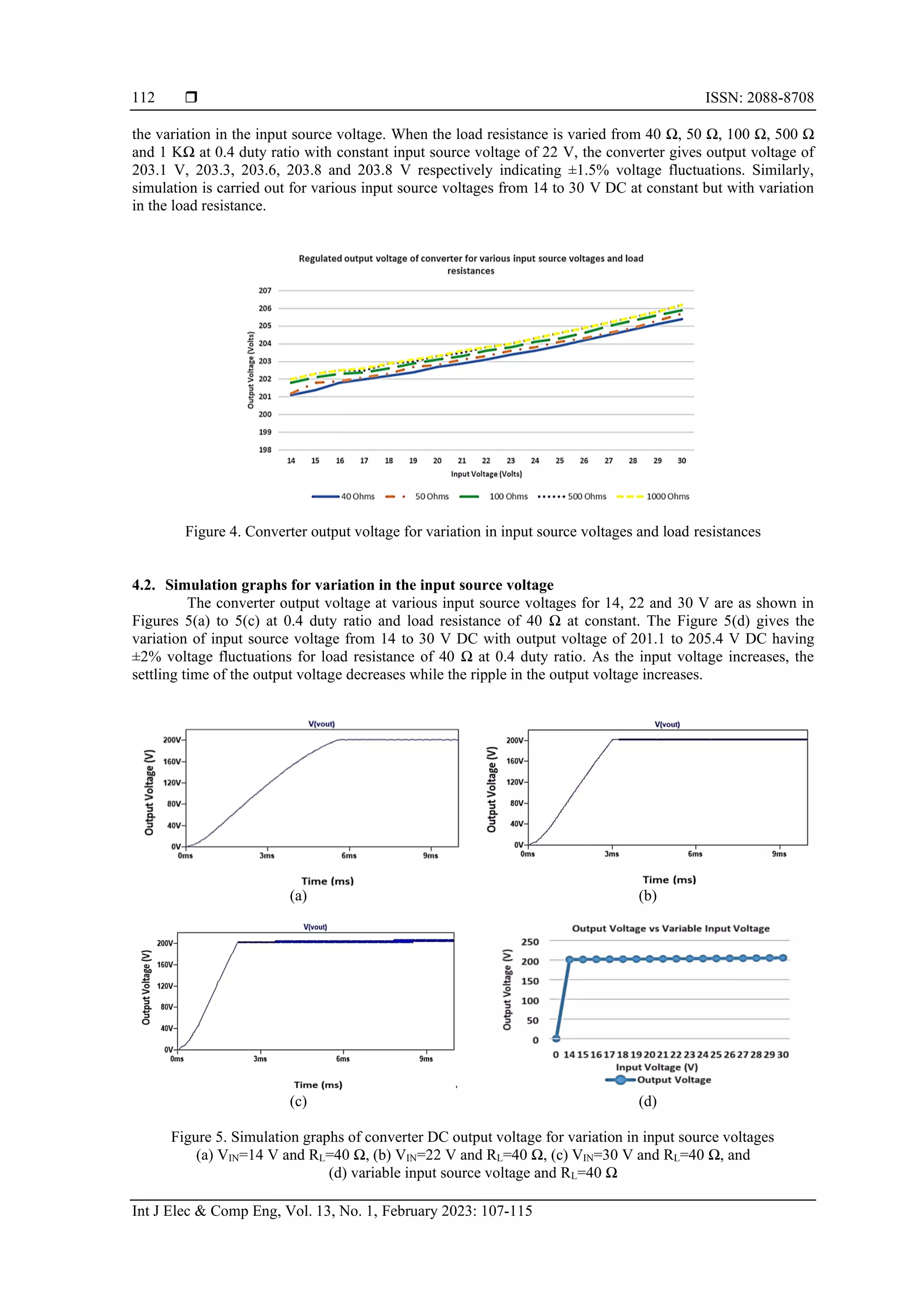
4.3. Simulation graphs for variation in the load resistance
The converter output voltage at various load resistances for 50 Ω, 500 Ω and 1 KΩ are as shown in
Figure 6(a) to 6(c) at 0.4 duty ratio and 22 V DC input source voltage at constant. The Figure 6(d) gives the
variation of load resistance from 40 Ω to 1 KΩ with output voltage of 203.1 to 203.8 V DC having ±1.5%
voltage fluctuations for input source voltage of 22 V DC at 0.4 duty ratio. The settling time of the output
voltage remains constant with the increase in the load resistance.
(a) (b)
(c) (d)
Figure 6. Simulation graphs of converter DC output voltage for variation in load resistances; (a) RL = 50 Ω
and VIN=22 V, (b) RL=500 Ω and VIN=22 V, (c) RL=1 KΩ and VIN=22 V, and
(d) variable load resistance and VIN=22 V
5. RELATIVE ASSESSMENT OF SLV VOLTAGE REGULATED CASCADED DC/DC
CONVERTER
The performance of the SLV voltage regulated cascaded DC/DC converter is compared to analyze
the percentage voltage fluctuations with other converters like PV converter in a standalone DC microgrid and
cascaded interleaved boost converter. It is observed that, SLV voltage regulated cascaded DC/DC converter
gives better results of regulated DC output voltage with minimal voltage fluctuations with variation in input
source voltage and load resistance on relative assessment with other converters.
5.1. PV converter in a standalone DC microgrid
The photovoltaic system was operated when the DC bus voltage was at ±5% of the nominal value
(600V). Under this condition, the PV converter regulated the bus voltage. When the battery energy storage
system was in the idle state, load demand was fulfilled by the photovoltaic system when the bus voltage was
-5% Vdc to +5% Vdc and it gives the details of the voltage regulation in standalone DC microgrids using
droop control method. In two scenarios, simulation using PSCAD software of the system was carried out
[26]. In relative assessment with these details, the PV converter gives regulated DC bus voltage with ±5%
voltage fluctuations of its nominal value whereas the SLV voltage regulated cascaded DC/DC converter
gives higher performance of regulated DC output voltage with ±2% voltage fluctuations for the variation in
the input source voltage from 14 to 30 V DC and ±1.5% voltage fluctuations for variation in load resistance
from 40 Ω to 1 KΩ indicating less voltage fluctuations.
5.2. Cascaded interleaved boost converter
The circuit for cascaded interleaved boost converter is as shown in Figure 7. The simulation of
cascaded interleaved boost converter has been carried out using LTspice XVII at 50 KHz switching
frequency. When the input source voltage is varied from 14 to 30 V DC, cascaded interleaved boost
converter using four switches gives regulated output voltage of 94.7 V with ±34% voltage fluctuations at 0.4](https://image.slidesharecdn.com/v1128117emr1aug2212apr22nn-221118060808-72d543b6/75/Source-load-variable-voltage-regulated-cascaded-DC-DC-converter-for-a-DC-microgrid-system-7-2048.jpg)
![ ISSN: 2088-8708
Int J Elec & Comp Eng, Vol. 13, No. 1, February 2023: 107-115
114
duty ratio but at higher duty ratio of 0.65 it gives 204.5 V with ±4% voltage fluctuations with higher output
voltage ripple in the waveform. When the load is varied from 40 Ω and 1 KΩ, cascaded interleaved boost
converter gives unstable output at 0.4 duty ratio and at higher duty ratio of 0.65 it gives regulated output
voltage with ±5.5% voltage fluctuations. In comparison, SLV voltage regulated cascaded DC/DC converter
using two switches gives better results of regulated DC output voltage with variation in the input source
voltage from 14 to 30 V DC with ±2% voltage fluctuations and for load resistance from 40 Ω to 1 KΩ with
±1.5% voltage fluctuations with lower ripple in the output voltage at lower duty ratio of 0.4 and lesser
voltage fluctuations. The comparative results of the converters are as shown in Table 1.
Figure 7. Cascaded interleaved boost converter
Table 1. Comparative assessment of output voltage of SLV voltage regulated cascaded DC/DC converter and
cascaded interleaved boost converter
Converter CIBC CIBC CIBC CIBC PC PC
Duty Ratio 0.4 0.4 0.65 0.65 0.4 0.4
VIN 40 Ω 1 KΩ 40 Ω 1 KΩ 40 Ω 1 KΩ
14 V 61.7 V Unstable 200.6 V 203.3 V 201.1 V 202.0 V
22 V 94.7 V Unstable 204.5 V 205.2 V 203.1 V 203.8 V
30 V 129.5 V 200.8 V 208.0 V 210.2 V 205.4 V 206.2 V
6. CONCLUSION
In this article, the SLV voltage regulated cascaded DC/DC converter is used to obtain regulated DC
output voltage with minimal voltage fluctuations. The performance of the converter is evaluated by varying
the input source voltage and load resistance. The inference of the simulation results is that i) the output
voltage is regulated at 203.1 V DC with ±2% voltage fluctuations for the variation of input source voltage
between 14 to 30 V DC; ii) when load resistance is varied between 40 Ω and 1 KΩ, the output voltage
remains constant with ±1.5% voltage fluctuations; iii) this is achieved at 0.4 duty ratio with the PWM gate
control circuit. Compared to other topologies, SLV voltage regulated cascaded DC/DC converter gives better
results of regulated DC output voltage with minimum voltage fluctuations, without use of sub circuits and at
lower duty ratio for reliable and secure operation of a DC microgrid system. In the future work, the
implementation of the suggested voltage regulation process is going to be implemented and the likely
complications caused from the practical application will be handled and conferred.
REFERENCES
[1] K. E. Lucas-Marcillo et al., “Novel robust methodology for controller design aiming to ensure DC microgrid stability under CPL
power variation,” IEEE Access, vol. 7, pp. 64206–64222, 2019, doi: 10.1109/ACCESS.2019.2915027.
[2] O. Ellabban, H. Abu-Rub, and F. Blaabjerg, “Renewable energy resources: Current status, future prospects and their enabling
technology,” Renewable and Sustainable Energy Reviews, vol. 39, pp. 748–764, Nov. 2014, doi: 10.1016/j.rser.2014.07.113.
[3] P. P. Altermatt et al., “Requirements of the paris climate agreement for the coming 10 566 years on investments, technical
roadmap, and expansion of PV manufacturing,” in 37th 567 European Photovoltaic Solar Energy Conference and Exhibition,
2020, vol. 567, pp. 1999–2004.
[4] M. Victoria et al., “Solar photovoltaics is ready to power a sustainable future,” Joule, vol. 5, no. 5, pp. 1041–1056, May 2021,
doi: 10.1016/j.joule.2021.03.005.
[5] BloombergNEF, “Energy transition investment trends,” BloombergNEF, 2021. Accessed: Apr. 08, 2022. [Online]. Available:
https://assets.bbhub.io/professional/sites/24/Energy-Transition-Investment-Trends_Free-Summary_Jan2021.pdf .
[6] Renewable Energy World Content Team, “IHS Markit releases new 2020 solar installation forecast in light of the impact of
COVID-19,” Renewable Energy World, 2020. https://www.renewableenergyworld.com/solar/ihs-markit-releases-new-2020-solar-
installation-forecast-in-light-of-the-impact-of-covid-19/#gref (accessed Apr. 08, 2022).](https://image.slidesharecdn.com/v1128117emr1aug2212apr22nn-221118060808-72d543b6/75/Source-load-variable-voltage-regulated-cascaded-DC-DC-converter-for-a-DC-microgrid-system-8-2048.jpg)
![Int J Elec & Comp Eng ISSN: 2088-8708
Source-load-variable voltage regulated cascaded DC/DC converter for a DC … (Radhika Salyam)
115
[7] A. Bhambhani, “Bloomberg new energy finance,” LONGi, 2021. https://taiyangnews.info/business/bnef-132-gw-solar-installed-
globally-in-2020/ (accessed Apr. 08, 2022).
[8] A. Jäger-Waldau, “Snapshot of photovoltaics-February 2020,” Energies, vol. 13, no. 4, 2020, doi: 10.3390/en13040930.
[9] A. Jäger-Waldau, “Snapshot of photovoltaics-March 2021,” EPJ Photovoltaics, vol. 12, 2021, doi: 10.1051/epjpv/2021002.
[10] M. Najafzadeh, R. Ahmadiahangar, O. Husev, I. Roasto, T. Jalakas, and A. Blinov, “Recent contributions, future prospects and
limitations of interlinking converter control in hybrid AC/DC microgrids,” IEEE Access, vol. 9, pp. 7960–7984, 2021, doi:
10.1109/ACCESS.2020.3049023.
[11] M. Akbari, S. M. M. Tafreshi, and M. A. Golkar, “Voltage control of a hybrid ac/dc microgrid in stand-alone operation mode,” in
ISGT2011-India, Dec. 2011, pp. 363–367, doi: 10.1109/ISET-India.2011.6145342.
[12] D. Salomonsson, L. Soder, and A. Sannino, “An adaptive control system for a DC microgrid for data centers,” IEEE Transactions
on Industry Applications, vol. 44, no. 6, pp. 1910–1917, 2008, doi: 10.1109/TIA.2008.2006398.
[13] H. Kakigano, Y. Miura, and T. Ise, “Low-voltage bipolar-type DC microgrid for super high quality distribution,” IEEE
Transactions on Power Electronics, vol. 25, no. 12, pp. 3066–3075, Dec. 2010, doi: 10.1109/TPEL.2010.2077682.
[14] D. Salomonsson, L. Soder, and A. Sannino, “Protection of low-voltage DC microgrids,” IEEE Transactions on Power Delivery,
vol. 24, no. 3, pp. 1045–1053, Jul. 2009, doi: 10.1109/TPWRD.2009.2016622.
[15] T.-F. Wu, K.-H. Sun, C.-L. Kuo, and C.-H. Chang, “Predictive current controlled 5-kW single-phase bidirectional inverter with
wide inductance variation for DC-microgrid applications,” IEEE Transactions on Power Electronics, vol. 25, no. 12,
pp. 3076–3084, Dec. 2010, doi: 10.1109/TPEL.2010.2087773.
[16] J. Sun, W. Lin, M. Hong, and K. A. Loparo, “Voltage regulation of DC-microgrid with PV and battery: A passivity method,”
IFAC-PapersOnLine, vol. 52, no. 16, pp. 753–758, 2019, doi: 10.1016/j.ifacol.2019.12.053.
[17] A. Timbus, M. Liserre, R. Teodorescu, P. Rodriguez, and F. Blaabjerg, “Evaluation of current controllers for distributed power
generation systems,” IEEE Transactions on Power Electronics, vol. 24, no. 3, pp. 654–664, Mar. 2009, doi:
10.1109/TPEL.2009.2012527.
[18] L. Malesani, L. Rossetto, P. Tenti, and P. Tomasin, “AC/DC/AC PWM converter with reduced energy storage in the DC link,”
IEEE Transactions on Industry Applications, vol. 31, no. 2, pp. 287–292, 1995, doi: 10.1109/28.370275.
[19] M.-T. Tsai and W. I. Tsai, “Analysis and design of three-phase AC-to-DC converters with high power factor and near-optimum
feedforward,” IEEE Transactions on Industrial Electronics, vol. 46, no. 3, pp. 535–543, Jun. 1999, doi: 10.1109/41.767060.
[20] X. Xiong and Y. Yang, “A photovoltaic-based DC microgrid system: Analysis, design and experimental results,” Electronics,
vol. 9, no. 6, Jun. 2020, doi: 10.3390/electronics9060941.
[21] Y. W. Li and C.-N. Kao, “An accurate power control strategy for power-electronics-interfaced distributed generation units
operating in a low-voltage multibus microgrid,” IEEE Transactions on Power Electronics, vol. 24, no. 12, pp. 2977–2988, Dec.
2009, doi: 10.1109/TPEL.2009.2022828.
[22] X. Lu, J. M. Guerrero, K. Sun, and J. C. Vasquez, “An improved droop control method for DC microgrids based on low
bandwidth communication With DC bus voltage restoration and enhanced current sharing accuracy,” IEEE Transactions on
Power Electronics, vol. 29, no. 4, pp. 1800–1812, Apr. 2014, doi: 10.1109/TPEL.2013.2266419.
[23] S. Peyghami, H. Mokhtari, P. C. Loh, P. Davari, and F. Blaabjerg, “Distributed primary and secondary power sharing in a droop-
controlled LVDC microgrid with merged AC and DC characteristics,” IEEE Transactions on Smart Grid, vol. 9, no. 3,
pp. 2284–2294, May 2018, doi: 10.1109/TSG.2016.2609853.
[24] S. Radhika and V. Margaret, “A comparative assessment of cascaded double voltage lift boost converter,” in 2020 Fifth
International Conference on Research in Computational Intelligence and Communication Networks (ICRCICN), Nov. 2020,
pp. 177–180, doi: 10.1109/ICRCICN50933.2020.9296190.
[25] Y. Li and S. Sathiakumar, “Improved quadratic boost converter based on the voltage lift technique,” in 2017 Asia Modelling
Symposium (AMS), Dec. 2017, pp. 139–144, doi: 10.1109/AMS.2017.30.
[26] D. R. Aryani and H. Song, “Voltage regulation in a stand-alone DC Microgrid,” IFAC-PapersOnLine, vol. 52, no. 4, pp. 36–39,
2019, doi: 10.1016/j.ifacol.2019.08.151.
BIOGRAPHIES OF AUTHORS
Radhika Salyam received a B.E. degree from Sir. M.V.I.T., Bangalore and M.E.
from U.V.C.E., Bangalore in Electrical and Electronics Engineering from Bangalore
University and pursuing PhD at Christ University, Bangalore. She is presently working as
Assistant Professor at B.I.T., Bangalore with 12+ years of work experience in the Department
of Electrical and Electronics Engineering. Areas of interest are power electronics, renewable
energy sources, power generation, VLSI design circuits, field theory and high voltage
engineering. She is a student member of IEEE and Life member of ISTE and MIE. She can be
contacted at email id: radhika.s@res.christuniversity.in.
Vijaya Margaret holds PhD from Christ University, Bangalore and secured 3rd
Rank in M Tech., VTU. She is presently working as Assistant Professor at Christ University,
Bangalore with 13+ work experience in Department of Electrical and Electronics
Engineering. Areas of interest are in establishing “Solar PV Rooftop Systems'' and previously
in “Computer Application in Industrial Drives''. She is life member of NGO SHUDDI, IEEE
Professional Membership, IEEE Power and Energy Society, IEEE Women in Engineering
Membership and Reviewer for IEEE Bangalore Section. She can be contacted at email id:
vijaya.margaret@christuniversity.in.](https://image.slidesharecdn.com/v1128117emr1aug2212apr22nn-221118060808-72d543b6/75/Source-load-variable-voltage-regulated-cascaded-DC-DC-converter-for-a-DC-microgrid-system-9-2048.jpg)


