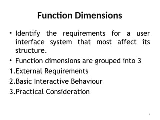
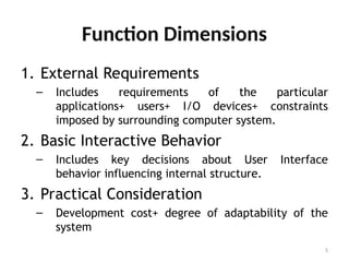
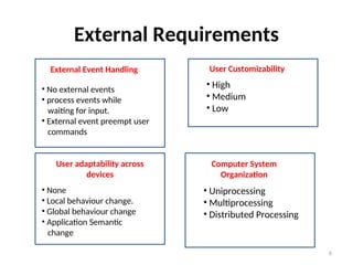
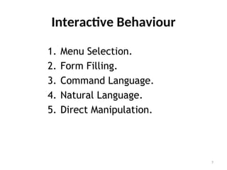
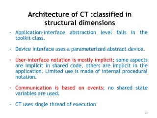
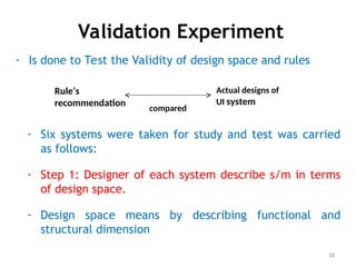
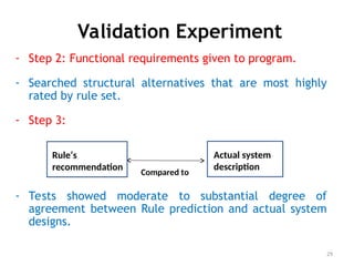
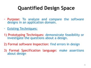
Download to read offline

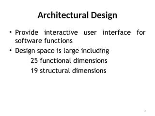
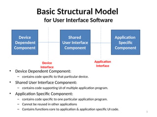


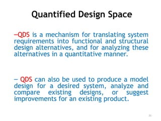


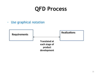


The document outlines architectural design guidelines for user interface architectures, detailing user interface components, function and structural dimensions, communication mechanisms, and design rules. It emphasizes the application of a quantified design space (QDS) for translating system requirements into functional and structural design alternatives while promoting user adaptability and customizability. The validation experiment demonstrates the correlation between design predictions and actual user interface system designs, highlighting quality function deployment as a technique for capturing customer needs during development.