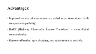
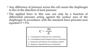
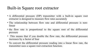
Differential Pressure Transmitter
Presented by
Dr.T.Mrunalini
Differential Pressure Transmitter:
• Electrical pressure sensor design works on the principle of differential capacitance
• Sensing element: taut metal diaphragm located equidistant between two stationary metal
surfaces, comprising three plates for a complementary pair of capacitors.
• An electrically insulating fill fluid (usually a liquid silicone compound) transfers motion
from the isolating diaphragms to the sensing diaphragm
• Any difference of pressure across the cell causes the diaphragm
to flex in the direction of least pressure
• The applied force in this case can only be a function of
differential pressure acting against the surface area of the
diaphragm in accordance with the standard force-pressure-area
equation F = PA.
Built-in Square root extractor
• A differential pressure (DP) transmitter with a built-in square root
extractor is designed to measure flow rates accurately
• The relationship between flow rate and differential pressure is non-
linear
• the flow rate is proportional to the square root of the differential
pressure
• This means that if you double the flow rate, the differential pressure
increases by a factor of four
• To convert the differential pressure reading into a linear flow rate, the
transmitter uses a square root extraction function.
• Having the square root extraction built into the transmitter simplifies
the system design and reduces the need for additional components
• It also ensures that the flow rate is accurately represented in real-time,
which is crucial for process control and monitoring
Square root extraction formula
To convert a a linear 4-20mA signal to a square root signal use the following
formula:
[Output Sq Rt] = 4mA + (4 x Square Root of ([Output Linear] – 4mA))
And to convert a square root signal to a linear 4-20mA signal use this formula:
[Output Linear] = 4mA + (([Output Sq Rt] - 4mA)^2 / 16)
Advantages:
• Improved version of transmitters are called smart transmitters (with
computer compatibility)
• HART (Highway Addressable Remote Transducer) – smart digital
communication
• Remote calibration, span changing, zero adjustmrnt also possible.

Smart - Differential Pressure Transmitter

  • 1.
  • 2.
    Differential Pressure Transmitter: •Electrical pressure sensor design works on the principle of differential capacitance • Sensing element: taut metal diaphragm located equidistant between two stationary metal surfaces, comprising three plates for a complementary pair of capacitors. • An electrically insulating fill fluid (usually a liquid silicone compound) transfers motion from the isolating diaphragms to the sensing diaphragm
  • 3.
    • Any differenceof pressure across the cell causes the diaphragm to flex in the direction of least pressure • The applied force in this case can only be a function of differential pressure acting against the surface area of the diaphragm in accordance with the standard force-pressure-area equation F = PA.
  • 4.
    Built-in Square rootextractor • A differential pressure (DP) transmitter with a built-in square root extractor is designed to measure flow rates accurately • The relationship between flow rate and differential pressure is non- linear • the flow rate is proportional to the square root of the differential pressure • This means that if you double the flow rate, the differential pressure increases by a factor of four • To convert the differential pressure reading into a linear flow rate, the transmitter uses a square root extraction function.
  • 5.
    • Having thesquare root extraction built into the transmitter simplifies the system design and reduces the need for additional components • It also ensures that the flow rate is accurately represented in real-time, which is crucial for process control and monitoring Square root extraction formula To convert a a linear 4-20mA signal to a square root signal use the following formula: [Output Sq Rt] = 4mA + (4 x Square Root of ([Output Linear] – 4mA)) And to convert a square root signal to a linear 4-20mA signal use this formula: [Output Linear] = 4mA + (([Output Sq Rt] - 4mA)^2 / 16)
  • 8.
    Advantages: • Improved versionof transmitters are called smart transmitters (with computer compatibility) • HART (Highway Addressable Remote Transducer) – smart digital communication • Remote calibration, span changing, zero adjustmrnt also possible.