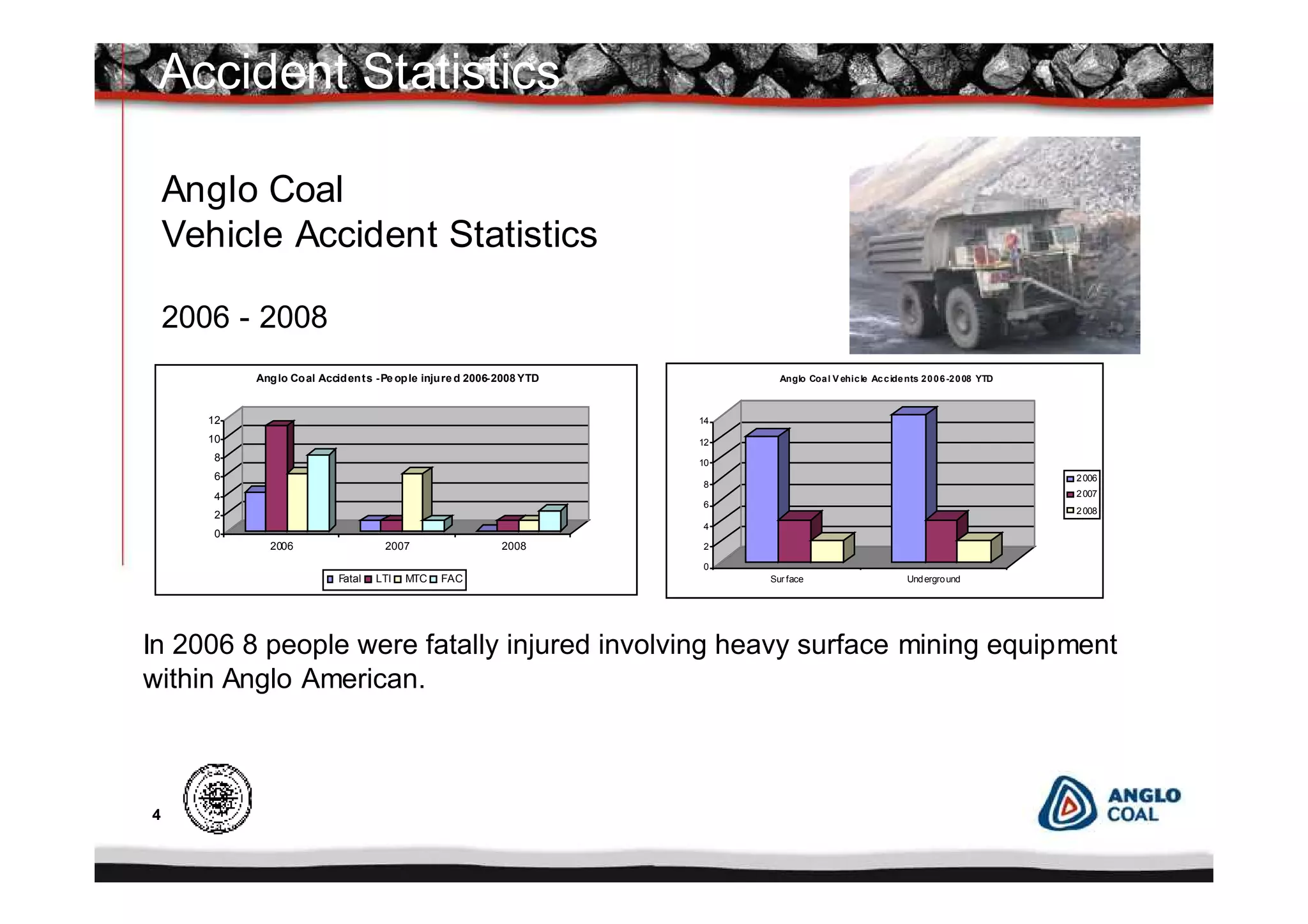
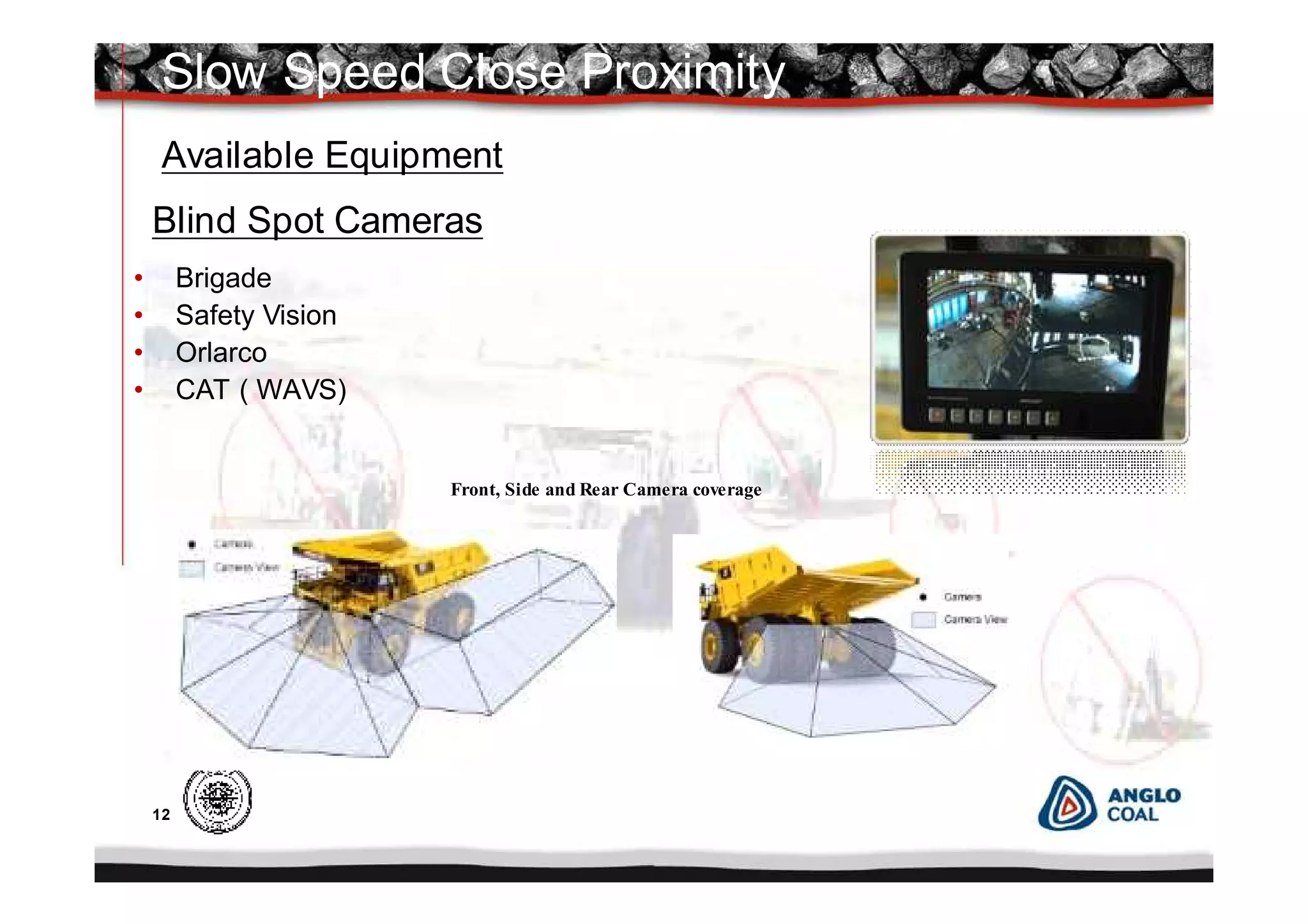
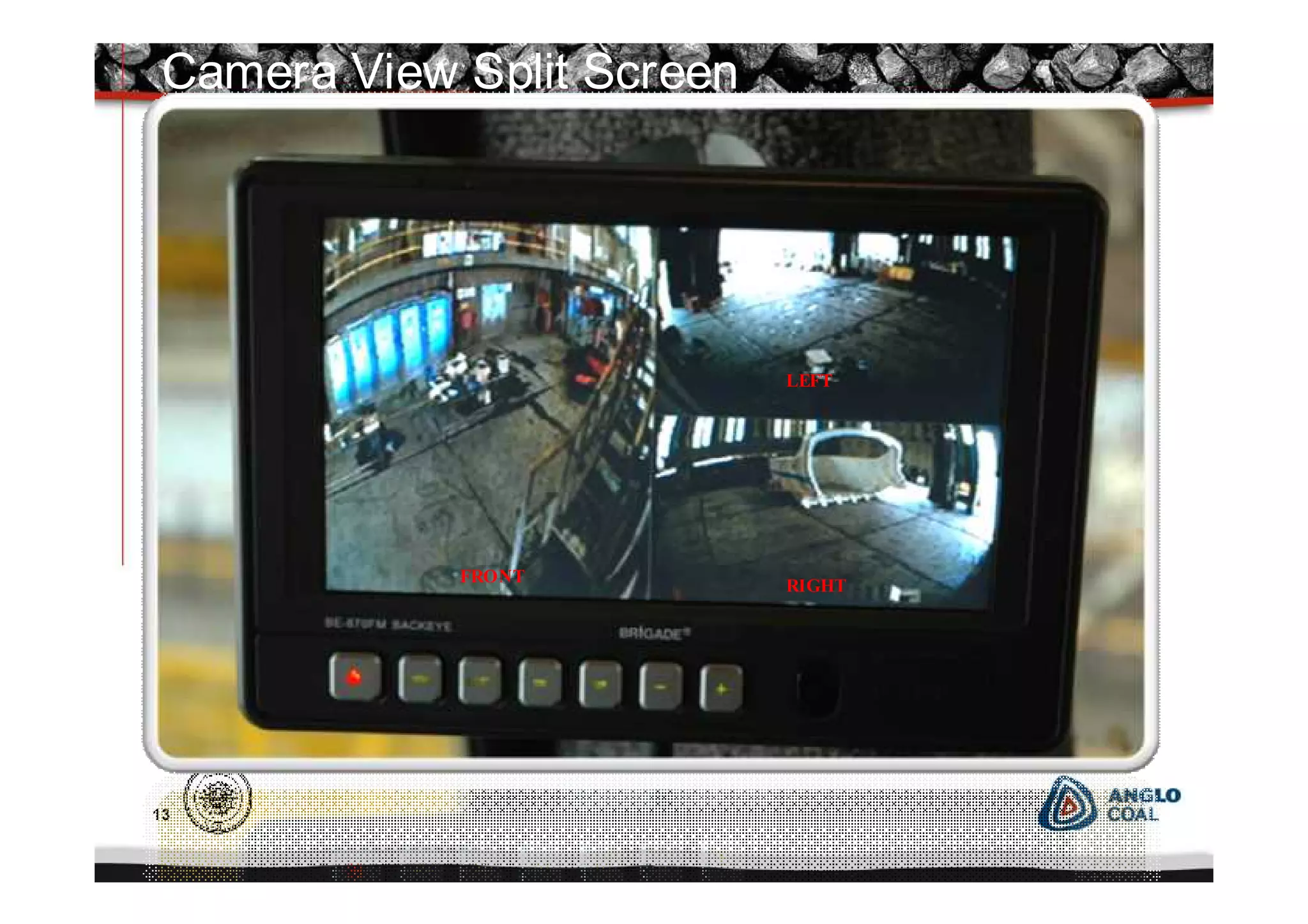
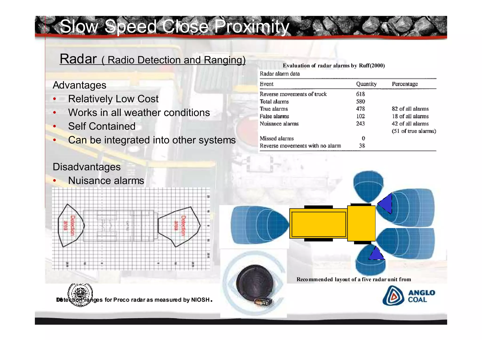
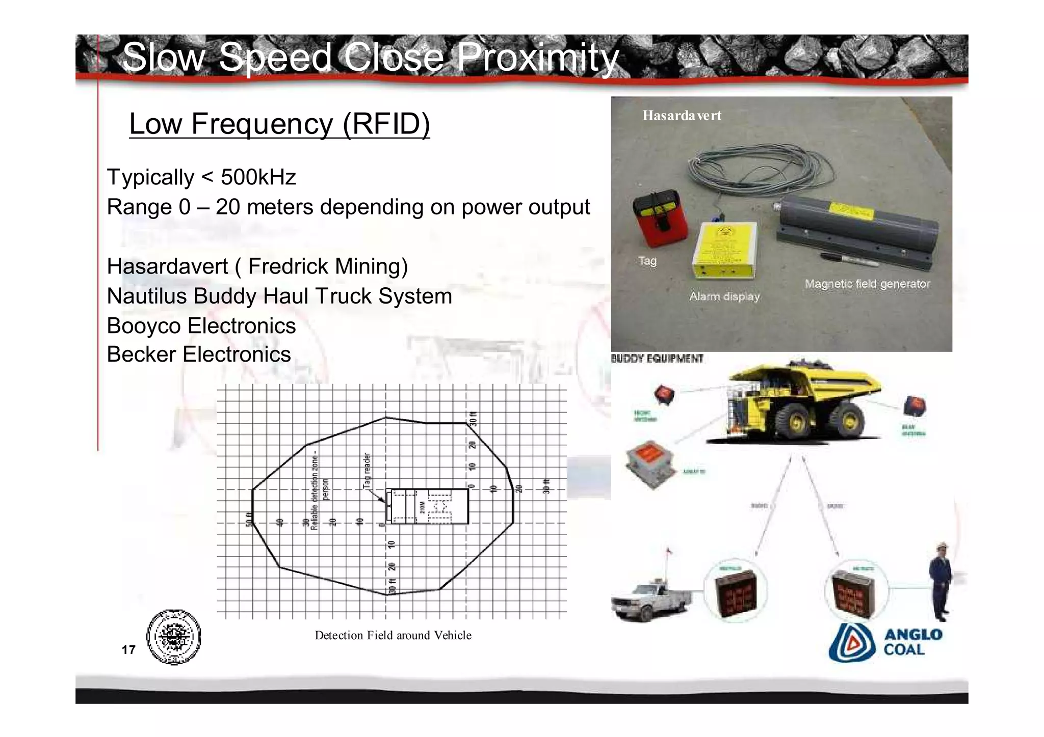
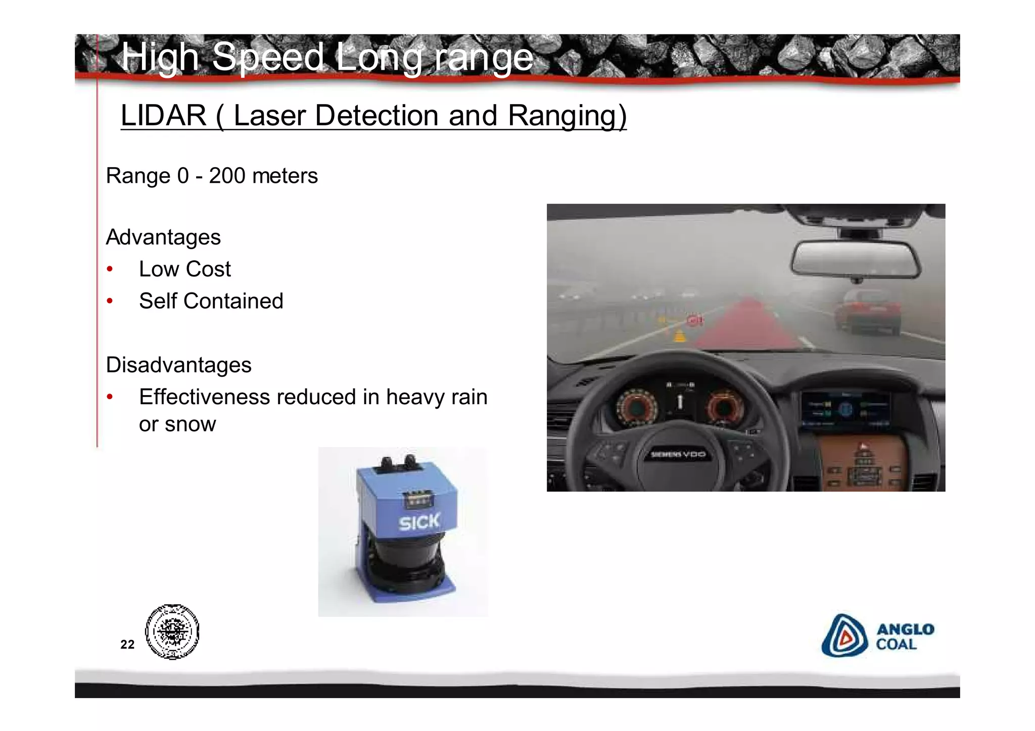
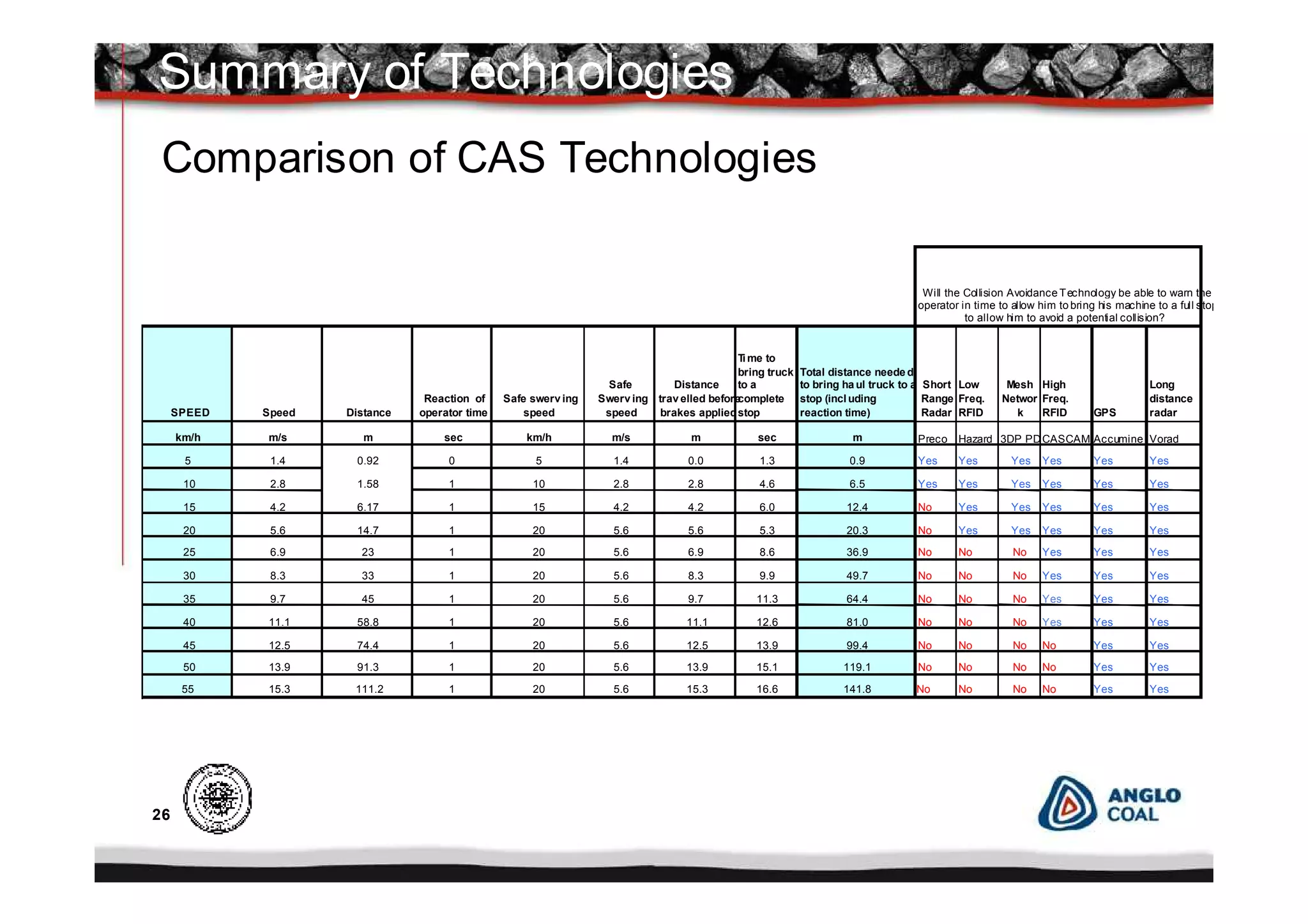
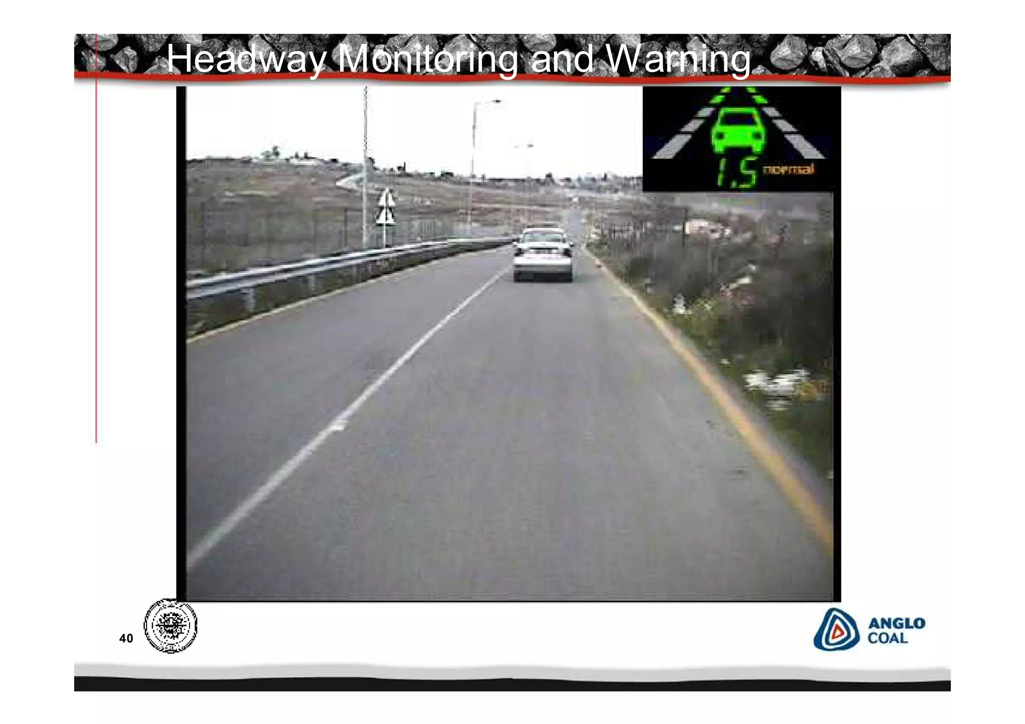
0
Vehicle and Personnel Collision
Warning Systems for Open Pit
and Underground 17 April 2008
Steven Niven
Anglo Coal Regional Engineering Services
1
Profile
Steven Niven
Control and Instrumentation Engineer
Anglo Coal Regional Engineering Services
Qualified as An Electrical Technician
British Steel Corporation 1978
South Wales
Emigrated to South Africa 1983 and
worked at Highveld Steel
Joined Anglo Coal 1985 Goedehoop
Colliery
Transferred to Anglo Coal Regional
Engineering Services 2006
Presenter
2
Content
• Introduction
• Accident Statistics
• Collision Avoidance Road Map
• Collision Avoidance Working Group
• Underground Collision Warning
Current Technologies
• Surface Collision Warning
• Types of Collisions and Scenarios
Current Technologies
– Slow Speed Close Proximity
– High Speed Long Range
– Technology Comparison
• Anglo Coal Underground Development Path
• Anglo Coal Open Pit Development Path
• Development Path
Presentation Content
3
I would like to share with you today, some of the technologies available,
developments, progress, and the learning points with regards to collision
warning, for both Underground and Open Pit operations within Anglo Coal.
Introduction
Introduction
This presentation is not to endorse any one product or company but to give an
overview of the various technologies, what is available and currently in use.
4
Accident Statistics
Anglo Coal
Vehicle Accident Statistics
0
2
4
6
8
10
12
2006 2007 2008
Anglo Coal Accidents -Pe ople injure d 2006-2008 YTD
Fatal LTI MTC FAC
2006 - 2008
In 2006 8 people were fatally injured involving heavy surface mining equipment
within Anglo American.
0
2
4
6
8
10
12
14
Sur face Underground
Anglo Coal V ehicle Accidents 2006-2008 YTD
2006
2007
2008
5
Mandate
The purpose of the working group was to:
• Investigate and determine what technologies were currently available to
assist in preventing collisions between vehicles and vehicle and vehicle to
personnel.
• What system were in use and their application.
• Were any system in development.
• To produce a report with a summary of the various technologies and
recommendations.
Colliosion Avoidance Working Group
6
Surface Collision Warning
7
Types of Collisions
• Close Proximity Slow Speed.
Within 20 meters at less than 15km/h
• Long Range High speed
At speeds from 15 to 60km/h
Open Pit Operations
8
Open Pit Collision Scenarios
9
These systems work on the principal of detecting potential threats (light
vehicles or other haul trucks) in the direction of travel and provide sufficient
warning time to allow the operator to take evasive action, either by applying
brakes or slowing down to a controllable safe speed before swerving to avoid
the vehicle.
Types of Collision Warning Systems
Slow Speed Close Proximity
High Speed Long Range
Typically these systems are designed to assist the operator at start-up (before
moving the machine) or whilst reversing.
10
Surface Collision Warning
Slow Speed Close Proximity
Collision Warning Equipment
11
Slow Speed Close Proximity
Vehicle Blind Spots
12
Available Equipment
Front, Side and Rear Camera coverage
• Brigade
• Safety Vision
• Orlarco
• CAT ( WAVS)
Slow Speed Close Proximity
Blind Spot Cameras
13
Camera View Split Screen
FRONT
RIGHT
LEFT
14
Cameras
Cameras ( Blind Spot)
Advantages
• Low Cost
• Off the shelf
• Can be integrated into other systems
Disadvantages
• Cannot work in all weather conditions
• Cameras must be kept clean
FLIR ( Forward Looking Infra Red) Pathfinder, Delphi
LEFT
FRONT
RIGHT
Slow Speed Close Proximity
15
Kriel Colliery
Pathfinder FLIR Camera
Pit to Tip
16
Advantages
• Relatively Low Cost
• Works in all weather conditions
• Self Contained
• Can be integrated into other systems
Disadvantages
• Nuisance alarms
Radar ( Radio Detection and Ranging) Evaluation of radar alarms by Ruff(2000)
Recommended layout of a five radar unit from
Detection ranges for Preco radar as measured by NIOSH.
Slow Speed Close Proximity
17
Low Frequency (RFID)
Typically < 500kHz
Range 0 – 20 meters depending on power output
Hasardavert ( Fredrick Mining)
Nautilus Buddy Haul Truck System
Booyco Electronics
Becker Electronics
Slow Speed Close Proximity
Hasardavert
Detection Field around Vehicle
18
To summarise all these systems can be used to prevent slow speed
collisions, but in some way they all have their limitations
• RFID requires everything to be tagged
• Cameras do not work so well in bad weather and require regular cleaning
• Radar if not set correctly can cause nuisance alarms.
But a combination of technologies can provide a good solution.
Summary
Slow Speed Close Proximity
19
Surface Collision Warning
High Speed Long Range
Collision Warning Equipment
20
High Speed Long Range
Long Range Radar
Range 0 – 150 meters
Advantages
•Works in all weather conditions
•Self Contained
•Intelligent system
•Can be integrated into other systems
Disadvantages
•Nuisance alarms
21
High Speed Long Range
High Frequency (RFID)
Typically > 500kHz
Range 0 – 150 meters
AMT (Australia)
Becker Electronics
Advantages
• Proven technology
• Positive identification
Disadvantages
• All vehicle require tagging
• Range fluctuations
• Multiple alarms
80 – 100 Mtrs
20 - 30 Mtrs
30 - 50 Mtrs
AMT CAS/CAM
B
E
C
K
E
R
C
A
S
3
0
0
CAS Controller
DPOD Recei ver
Vehicle
Transponder
(TAG)
AMT CAS / CAM
22
Range 0 - 200 meters
Advantages
• Low Cost
• Self Contained
Disadvantages
• Effectiveness reduced in heavy rain
or snow
High Speed Long range
LIDAR ( Laser Detection and Ranging)
23
Many auto mobile manufacturers already offer adaptive cruise control ( ACC )
Collision Warning with Auto Braking (CWAB) or Lane Departure Warning (LDW)
as an option on their vehicles.
These adaptive cruise control (ACC) systems, use either laser beams or radar to
measure the distance from the vehicle they are in, to the car ahead and its
speed relative to theirs.
If a car crosses into the lane ahead, and the distance is now less than the preset
minimum (typically a 1 – 2 second interval of separation), the system applies the
brakes, slowing the car with a maximum deceleration of 3.5 m/s2 until it is
following at the desired distance.
If the leading car speeds up or moves out of the lane, the system opens the throttle
until the trailing car has returned to the cruise control speed set by the driver
Note that to avoid liability claims in the event of collisions between cars equipped
with adaptive cruise control systems, manufacturers of these systems and the
automotive companies that use them are careful not to refer to them as SAFETY
DEVICES. Instead, they are being marketed as DRIVER AIDS, mere conveniences
made possible by new technologies.
Lidar / Radar / Vision Systems
24
High Speed Long Range
GPS Systems
Acumine, FLARM
• Range 0 – 500 meters typically restricted by RF range
• Accuracy 3 - 5 metres
• Highly selective 3D track prediction minimizes "nuisance warnings"
• Simple driver cabin installation, not requiring specialists
• No radio network infrastructure needed, works anywhere with GPS
• Well proven technology outside of mining
• Recalculation and retransmission every second
• Usable in all vehicle types (Haul trucks, light vehicles, graders, etc)
configurable vehicle size, type and characteristic
25
Other Technologies
Wireless Mesh Networks
A system is still in development between Freeport (Phelps Dodge) and
Motorola
Vision Systems
Mobileye
Delphi
These systems are already in use in many on road vehicles for lane departure,
object detection and adaptive cruise control.
26
Comparison of CAS Technologies
SPEED Speed Distance
Reaction of
operator time
Safe swerv ing
speed
Safe
Swerv ing
speed
Distance
trav elled before
brakes applied
Ti me to
bring truck
to a
complete
stop
Total distance neede d
to bring ha ul truck to a
stop (incl uding
reaction time)
Short
Range
Radar
Low
Freq.
RFID
Mesh
Networ
k
High
Freq.
RFID GPS
Long
distance
radar
km/h m/s m sec km/h m/s m sec m Preco Hazard 3DP PDCASCAM Accumine Vorad
5 1.4 0.92 0 5 1.4 0.0 1.3 0.9 Yes Yes Yes Yes Yes Yes
10 2.8 1.58 1 10 2.8 2.8 4.6 6.5 Yes Yes Yes Yes Yes Yes
15 4.2 6.17 1 15 4.2 4.2 6.0 12.4 No Yes Yes Yes Yes Yes
20 5.6 14.7 1 20 5.6 5.6 5.3 20.3 No Yes Yes Yes Yes Yes
25 6.9 23 1 20 5.6 6.9 8.6 36.9 No No No Yes Yes Yes
30 8.3 33 1 20 5.6 8.3 9.9 49.7 No No No Yes Yes Yes
35 9.7 45 1 20 5.6 9.7 11.3 64.4 No No No Yes Yes Yes
40 11.1 58.8 1 20 5.6 11.1 12.6 81.0 No No No Yes Yes Yes
45 12.5 74.4 1 20 5.6 12.5 13.9 99.4 No No No No Yes Yes
50 13.9 91.3 1 20 5.6 13.9 15.1 119.1 No No No No Yes Yes
55 15.3 111.2 1 20 5.6 15.3 16.6 141.8 No No No No Yes Yes
Will the Collision Avoidance Technology be able to warn the
operator in time to allow him to bring his machine to a full stop
to allow him to avoid a potential collision?
Summary of Technologies
27
Surface Collision Warning
Anglo Coal Surface
Collision Warning System
Road Map
28
Anglo Coal
Camera System
• June 2007 installation of a 3 camera Orlarco system at Klienkopjies
to evaluate
• June 2007 testing of Path Finder Forward looking Infrared cameras
(FLIR) at Kriel and Klienkopjies
• September 2007 installation of (Brigade) cameras and
FLIR cameras on 5 Haul trucks at Kriel colliery
• September 2007 commenced installation of combined Becker RFID
and camera collision avoidance system at
Landau. (decision made to keep camera systems separate)
• March 2008 Contract awarded for the installation of
cameras including FLIR for haul trucks and various vehicles.
• March to September 2008 Rollout of Cameras to all operations
Mafube, Kriel, Isibonello, Landau, Klienkopjies and New Vaal
29
RFID Systems
• May 2007 order placed for trial of RFID system at Landau
• September 2007 commenced installation of Becker RFID and
camera collision avoidance system at Landau to evaluate.
Vehicles equipped: 4 Haul trucks, 2 Dump trucks,( 4 Antenna
Systems) Grader, FEL, ADT, Shovel, Dozer and 16 bakies
• November 2007 training of operators and engineering personnel
• December/ January 2007 testing of system
• January 2008 operator feedback survey (positive)
• March 2008 Contract awarded for the group installation of Cameras
and RFID
• April to December 2008 Rollout to all operations Landau,Mafube,
Kriel, Isibonello, Klienkopjies and New Vaal
Anglo Coal
30
Project Successes and Challenges
• Regular meeting with supplier during project
• Buy in from operators and honest feedback
• Involvement and co operation from mine personnel
• Sharing of information and learning's with ACA Drayton and their
experiences on the testing of the AMT RFID system
• Delays in equipment delivery
• The RFID antennas were modified to incorporate the Dpods and
antennas into one unit not two separate pieces of equipment new
electronic boards had to be designed, manufactured and tested
• Incorporated vehicle tags into antenna electronics for simplification of
system on larger vehicles new circuit boards designed and
manufactured
• CAS unit software rewritten to accommodate changes to tags
amplifiers and introduce a second triggering level for LDV’s
Collision Warning Open Pit Operations
31
Collision Warning Underground Operations
Underground Collision Warning
32
Fredrick Mining
Tram Guard
Collision Warning Underground Operations
Typically < 500kHz
Range 6 – 20 meters depending on power output limitations
Booyco Electronics
Tram Guard ( Fredrick Mining)
Becker Electronics
Nautilus
Advantages
• Stable field
• Multiple detection zones
• Ability to penetrate stick sides
Disadvantages
• Cost
Low Frequency (RFID)
Field Generators
PAD worn by the miner
Vehicle Unit
33
Surface Collision Warning
Anglo Coal Underground
Collision Warning System
Road Map
34
• March 2006 Booyco/VAK CWS 500 system introduced to
Greenside Mapula section for testing.
• May 2007 Modification to introduce two zone detection and driver
warning (CWS 800).
• October 2007 Final testing of CWS 800
• November 2007 CPC approval for project approval to roll out to all
operations.
• January 2008 commencement of roll out project to Greenside,
Goedehoop, Kriel, New Denmark
• October 2008 completion of project
Collision Warning Underground Operations
Anglo Coal Road Map
35
CWS 800 Components
CWS 800 Components
36
Antennas installed on drivers side
Antennas installed diagonally
opposite
Plotting of fields around Vehicle
Antennas installed on opposite side
37
The development of a Last Line of Support (LLOS) warning device had
been undertaken in November 2006, as there was no commercially
available equipment.
Several different technologies were initially tested with some success
but there were limitation for these technologies in the underground
environment. (Infrared, Ultrasonic)
A decision was made to adapt the Underground Personnel Warning
System technology (Low Frequecy RFID) to suit this application.
The prototype has been completed and will be sent to Kriel in April
2008 for testing and evaluation.
Challenges for this device are, to limit the power consumption so that
the device can be powered from standard cap lamp batteries, with a
four day life before being changed, ExIa certification, and to produce a
narrow detection field .
2nd Last Line of Support Warning Device
38
•2nd last line proximity warning
device – one unit built at Booyco,
will be installed at Kriel by end
March for testing
•Will use the same technology as
the personnel warning system
2nd Last Line of Support warning Device
39
References
CDC RI 9672 Ruff, T. (2007). Recommendations for Evaluating & Implementing Proximity Warning
Systems on Surface Mining Equipment.
AAC April 2007 Collision Avoidance Systems Technical Report
Ruff, T. and Holden, T. (2003). Preventing collisions involving surface mining
Acknowledgments
To the Anglo American Collision working Group
H. Faul (ATD); D. Janicijevic (Anglo Platinum); O. Munoz (Anglo Base); A. Naidoo (Anglo Ferrous); V.
Nhlapo (Anglo Platinum) ; S. Niven (Anglo Coal); E. Riffo (Anglo Base); M Ruplal (ATD)
Acknowledgements and References
40
Headway Monitoring and Warning
41
Lane Deviation Warning Day Time
42
Lane Deviation Warning Night Time
43
Blind Spot Monitoring
44
Adaptive Cruise Control and Braking
45
Discussion
46
THANK YOU
AND LETS NOT MEET BY ACCIDENT

Sistema alerta colisión

  • 1.
    0 Vehicle and PersonnelCollision Warning Systems for Open Pit and Underground 17 April 2008 Steven Niven Anglo Coal Regional Engineering Services
  • 2.
    1 Profile Steven Niven Control andInstrumentation Engineer Anglo Coal Regional Engineering Services Qualified as An Electrical Technician British Steel Corporation 1978 South Wales Emigrated to South Africa 1983 and worked at Highveld Steel Joined Anglo Coal 1985 Goedehoop Colliery Transferred to Anglo Coal Regional Engineering Services 2006 Presenter
  • 3.
    2 Content • Introduction • AccidentStatistics • Collision Avoidance Road Map • Collision Avoidance Working Group • Underground Collision Warning Current Technologies • Surface Collision Warning • Types of Collisions and Scenarios Current Technologies – Slow Speed Close Proximity – High Speed Long Range – Technology Comparison • Anglo Coal Underground Development Path • Anglo Coal Open Pit Development Path • Development Path Presentation Content
  • 4.
    3 I would liketo share with you today, some of the technologies available, developments, progress, and the learning points with regards to collision warning, for both Underground and Open Pit operations within Anglo Coal. Introduction Introduction This presentation is not to endorse any one product or company but to give an overview of the various technologies, what is available and currently in use.
  • 5.
    4 Accident Statistics Anglo Coal VehicleAccident Statistics 0 2 4 6 8 10 12 2006 2007 2008 Anglo Coal Accidents -Pe ople injure d 2006-2008 YTD Fatal LTI MTC FAC 2006 - 2008 In 2006 8 people were fatally injured involving heavy surface mining equipment within Anglo American. 0 2 4 6 8 10 12 14 Sur face Underground Anglo Coal V ehicle Accidents 2006-2008 YTD 2006 2007 2008
  • 6.
    5 Mandate The purpose ofthe working group was to: • Investigate and determine what technologies were currently available to assist in preventing collisions between vehicles and vehicle and vehicle to personnel. • What system were in use and their application. • Were any system in development. • To produce a report with a summary of the various technologies and recommendations. Colliosion Avoidance Working Group
  • 7.
  • 8.
    7 Types of Collisions •Close Proximity Slow Speed. Within 20 meters at less than 15km/h • Long Range High speed At speeds from 15 to 60km/h Open Pit Operations
  • 9.
  • 10.
    9 These systems workon the principal of detecting potential threats (light vehicles or other haul trucks) in the direction of travel and provide sufficient warning time to allow the operator to take evasive action, either by applying brakes or slowing down to a controllable safe speed before swerving to avoid the vehicle. Types of Collision Warning Systems Slow Speed Close Proximity High Speed Long Range Typically these systems are designed to assist the operator at start-up (before moving the machine) or whilst reversing.
  • 11.
    10 Surface Collision Warning SlowSpeed Close Proximity Collision Warning Equipment
  • 12.
    11 Slow Speed CloseProximity Vehicle Blind Spots
  • 13.
    12 Available Equipment Front, Sideand Rear Camera coverage • Brigade • Safety Vision • Orlarco • CAT ( WAVS) Slow Speed Close Proximity Blind Spot Cameras
  • 14.
    13 Camera View SplitScreen FRONT RIGHT LEFT
  • 15.
    14 Cameras Cameras ( BlindSpot) Advantages • Low Cost • Off the shelf • Can be integrated into other systems Disadvantages • Cannot work in all weather conditions • Cameras must be kept clean FLIR ( Forward Looking Infra Red) Pathfinder, Delphi LEFT FRONT RIGHT Slow Speed Close Proximity
  • 16.
  • 17.
    16 Advantages • Relatively LowCost • Works in all weather conditions • Self Contained • Can be integrated into other systems Disadvantages • Nuisance alarms Radar ( Radio Detection and Ranging) Evaluation of radar alarms by Ruff(2000) Recommended layout of a five radar unit from Detection ranges for Preco radar as measured by NIOSH. Slow Speed Close Proximity
  • 18.
    17 Low Frequency (RFID) Typically< 500kHz Range 0 – 20 meters depending on power output Hasardavert ( Fredrick Mining) Nautilus Buddy Haul Truck System Booyco Electronics Becker Electronics Slow Speed Close Proximity Hasardavert Detection Field around Vehicle
  • 19.
    18 To summarise allthese systems can be used to prevent slow speed collisions, but in some way they all have their limitations • RFID requires everything to be tagged • Cameras do not work so well in bad weather and require regular cleaning • Radar if not set correctly can cause nuisance alarms. But a combination of technologies can provide a good solution. Summary Slow Speed Close Proximity
  • 20.
    19 Surface Collision Warning HighSpeed Long Range Collision Warning Equipment
  • 21.
    20 High Speed LongRange Long Range Radar Range 0 – 150 meters Advantages •Works in all weather conditions •Self Contained •Intelligent system •Can be integrated into other systems Disadvantages •Nuisance alarms
  • 22.
    21 High Speed LongRange High Frequency (RFID) Typically > 500kHz Range 0 – 150 meters AMT (Australia) Becker Electronics Advantages • Proven technology • Positive identification Disadvantages • All vehicle require tagging • Range fluctuations • Multiple alarms 80 – 100 Mtrs 20 - 30 Mtrs 30 - 50 Mtrs AMT CAS/CAM B E C K E R C A S 3 0 0 CAS Controller DPOD Recei ver Vehicle Transponder (TAG) AMT CAS / CAM
  • 23.
    22 Range 0 -200 meters Advantages • Low Cost • Self Contained Disadvantages • Effectiveness reduced in heavy rain or snow High Speed Long range LIDAR ( Laser Detection and Ranging)
  • 24.
    23 Many auto mobilemanufacturers already offer adaptive cruise control ( ACC ) Collision Warning with Auto Braking (CWAB) or Lane Departure Warning (LDW) as an option on their vehicles. These adaptive cruise control (ACC) systems, use either laser beams or radar to measure the distance from the vehicle they are in, to the car ahead and its speed relative to theirs. If a car crosses into the lane ahead, and the distance is now less than the preset minimum (typically a 1 – 2 second interval of separation), the system applies the brakes, slowing the car with a maximum deceleration of 3.5 m/s2 until it is following at the desired distance. If the leading car speeds up or moves out of the lane, the system opens the throttle until the trailing car has returned to the cruise control speed set by the driver Note that to avoid liability claims in the event of collisions between cars equipped with adaptive cruise control systems, manufacturers of these systems and the automotive companies that use them are careful not to refer to them as SAFETY DEVICES. Instead, they are being marketed as DRIVER AIDS, mere conveniences made possible by new technologies. Lidar / Radar / Vision Systems
  • 25.
    24 High Speed LongRange GPS Systems Acumine, FLARM • Range 0 – 500 meters typically restricted by RF range • Accuracy 3 - 5 metres • Highly selective 3D track prediction minimizes "nuisance warnings" • Simple driver cabin installation, not requiring specialists • No radio network infrastructure needed, works anywhere with GPS • Well proven technology outside of mining • Recalculation and retransmission every second • Usable in all vehicle types (Haul trucks, light vehicles, graders, etc) configurable vehicle size, type and characteristic
  • 26.
    25 Other Technologies Wireless MeshNetworks A system is still in development between Freeport (Phelps Dodge) and Motorola Vision Systems Mobileye Delphi These systems are already in use in many on road vehicles for lane departure, object detection and adaptive cruise control.
  • 27.
    26 Comparison of CASTechnologies SPEED Speed Distance Reaction of operator time Safe swerv ing speed Safe Swerv ing speed Distance trav elled before brakes applied Ti me to bring truck to a complete stop Total distance neede d to bring ha ul truck to a stop (incl uding reaction time) Short Range Radar Low Freq. RFID Mesh Networ k High Freq. RFID GPS Long distance radar km/h m/s m sec km/h m/s m sec m Preco Hazard 3DP PDCASCAM Accumine Vorad 5 1.4 0.92 0 5 1.4 0.0 1.3 0.9 Yes Yes Yes Yes Yes Yes 10 2.8 1.58 1 10 2.8 2.8 4.6 6.5 Yes Yes Yes Yes Yes Yes 15 4.2 6.17 1 15 4.2 4.2 6.0 12.4 No Yes Yes Yes Yes Yes 20 5.6 14.7 1 20 5.6 5.6 5.3 20.3 No Yes Yes Yes Yes Yes 25 6.9 23 1 20 5.6 6.9 8.6 36.9 No No No Yes Yes Yes 30 8.3 33 1 20 5.6 8.3 9.9 49.7 No No No Yes Yes Yes 35 9.7 45 1 20 5.6 9.7 11.3 64.4 No No No Yes Yes Yes 40 11.1 58.8 1 20 5.6 11.1 12.6 81.0 No No No Yes Yes Yes 45 12.5 74.4 1 20 5.6 12.5 13.9 99.4 No No No No Yes Yes 50 13.9 91.3 1 20 5.6 13.9 15.1 119.1 No No No No Yes Yes 55 15.3 111.2 1 20 5.6 15.3 16.6 141.8 No No No No Yes Yes Will the Collision Avoidance Technology be able to warn the operator in time to allow him to bring his machine to a full stop to allow him to avoid a potential collision? Summary of Technologies
  • 28.
    27 Surface Collision Warning AngloCoal Surface Collision Warning System Road Map
  • 29.
    28 Anglo Coal Camera System •June 2007 installation of a 3 camera Orlarco system at Klienkopjies to evaluate • June 2007 testing of Path Finder Forward looking Infrared cameras (FLIR) at Kriel and Klienkopjies • September 2007 installation of (Brigade) cameras and FLIR cameras on 5 Haul trucks at Kriel colliery • September 2007 commenced installation of combined Becker RFID and camera collision avoidance system at Landau. (decision made to keep camera systems separate) • March 2008 Contract awarded for the installation of cameras including FLIR for haul trucks and various vehicles. • March to September 2008 Rollout of Cameras to all operations Mafube, Kriel, Isibonello, Landau, Klienkopjies and New Vaal
  • 30.
    29 RFID Systems • May2007 order placed for trial of RFID system at Landau • September 2007 commenced installation of Becker RFID and camera collision avoidance system at Landau to evaluate. Vehicles equipped: 4 Haul trucks, 2 Dump trucks,( 4 Antenna Systems) Grader, FEL, ADT, Shovel, Dozer and 16 bakies • November 2007 training of operators and engineering personnel • December/ January 2007 testing of system • January 2008 operator feedback survey (positive) • March 2008 Contract awarded for the group installation of Cameras and RFID • April to December 2008 Rollout to all operations Landau,Mafube, Kriel, Isibonello, Klienkopjies and New Vaal Anglo Coal
  • 31.
    30 Project Successes andChallenges • Regular meeting with supplier during project • Buy in from operators and honest feedback • Involvement and co operation from mine personnel • Sharing of information and learning's with ACA Drayton and their experiences on the testing of the AMT RFID system • Delays in equipment delivery • The RFID antennas were modified to incorporate the Dpods and antennas into one unit not two separate pieces of equipment new electronic boards had to be designed, manufactured and tested • Incorporated vehicle tags into antenna electronics for simplification of system on larger vehicles new circuit boards designed and manufactured • CAS unit software rewritten to accommodate changes to tags amplifiers and introduce a second triggering level for LDV’s Collision Warning Open Pit Operations
  • 32.
    31 Collision Warning UndergroundOperations Underground Collision Warning
  • 33.
    32 Fredrick Mining Tram Guard CollisionWarning Underground Operations Typically < 500kHz Range 6 – 20 meters depending on power output limitations Booyco Electronics Tram Guard ( Fredrick Mining) Becker Electronics Nautilus Advantages • Stable field • Multiple detection zones • Ability to penetrate stick sides Disadvantages • Cost Low Frequency (RFID) Field Generators PAD worn by the miner Vehicle Unit
  • 34.
    33 Surface Collision Warning AngloCoal Underground Collision Warning System Road Map
  • 35.
    34 • March 2006Booyco/VAK CWS 500 system introduced to Greenside Mapula section for testing. • May 2007 Modification to introduce two zone detection and driver warning (CWS 800). • October 2007 Final testing of CWS 800 • November 2007 CPC approval for project approval to roll out to all operations. • January 2008 commencement of roll out project to Greenside, Goedehoop, Kriel, New Denmark • October 2008 completion of project Collision Warning Underground Operations Anglo Coal Road Map
  • 36.
  • 37.
    36 Antennas installed ondrivers side Antennas installed diagonally opposite Plotting of fields around Vehicle Antennas installed on opposite side
  • 38.
    37 The development ofa Last Line of Support (LLOS) warning device had been undertaken in November 2006, as there was no commercially available equipment. Several different technologies were initially tested with some success but there were limitation for these technologies in the underground environment. (Infrared, Ultrasonic) A decision was made to adapt the Underground Personnel Warning System technology (Low Frequecy RFID) to suit this application. The prototype has been completed and will be sent to Kriel in April 2008 for testing and evaluation. Challenges for this device are, to limit the power consumption so that the device can be powered from standard cap lamp batteries, with a four day life before being changed, ExIa certification, and to produce a narrow detection field . 2nd Last Line of Support Warning Device
  • 39.
    38 •2nd last lineproximity warning device – one unit built at Booyco, will be installed at Kriel by end March for testing •Will use the same technology as the personnel warning system 2nd Last Line of Support warning Device
  • 40.
    39 References CDC RI 9672Ruff, T. (2007). Recommendations for Evaluating & Implementing Proximity Warning Systems on Surface Mining Equipment. AAC April 2007 Collision Avoidance Systems Technical Report Ruff, T. and Holden, T. (2003). Preventing collisions involving surface mining Acknowledgments To the Anglo American Collision working Group H. Faul (ATD); D. Janicijevic (Anglo Platinum); O. Munoz (Anglo Base); A. Naidoo (Anglo Ferrous); V. Nhlapo (Anglo Platinum) ; S. Niven (Anglo Coal); E. Riffo (Anglo Base); M Ruplal (ATD) Acknowledgements and References
  • 41.
  • 42.
  • 43.
  • 44.
  • 45.
  • 46.
  • 47.
    46 THANK YOU AND LETSNOT MEET BY ACCIDENT