Chapter 2 discusses signal sampling and quantization, emphasizing the conversion of continuous-time signals to discrete ones through analog-to-digital (A/D) conversion and the reconstruction process via digital-to-analog (D/A) conversion. It explains the importance of sampling frequency, the consequences of aliasing, and the conditions required for perfect signal reconstruction based on the Shannon sampling theorem. Additionally, the chapter covers quantization, distinguishing between unipolar and bipolar quantizers, and introduces concepts of periodicity in discrete-time sequences.


![Sampling
• The reciprocal 𝐹𝑠 is called sampling frequency (cycles per second or Hz) or sampling rate (samples per second).
• Periodic or uniform sampling, a sequence of samples 𝑥[𝑛] is obtained from a continuous-time signal 𝑥𝑐 [𝑡] by
taking values at equally spaced points in time. T is the fixed time interval between samples, is known as the
the sampling period.
𝐹𝑠 = 1 𝑇
Sampling rate
Sample per second (Hz)
Sampling period
(second)
Sample and Hold
4
CEN352 Dr. Nassim Ammour King Saud University
Example sampling period: T = 125 µs.
sampling rate: 𝐹𝑠 =1/125µs = 8,000 samples per second (Hz).](https://image.slidesharecdn.com/chap2sampling-240229043737-7ced4008/75/Signal-Sampling-and-signal-quantization-4-2048.jpg)
![Sampling Process
• The sampling of a continuous-timesignal 𝑥[𝑛]
is equivalent to multiply the signal with pulse
train signal 𝑆(𝑡).
𝑥 𝑡 Input analog signal
𝑆(𝑡) Pulse train
𝑥𝑠 𝑡 = 𝑥 𝑡 ∙ 𝑆(𝑡) =
𝑛=−∞
∞
)
𝑥𝑎 𝑛𝑇𝑠 𝛿(𝑡 − 𝑛𝑇𝑠
Sampled signal
5
CEN352 Dr. Nassim Ammour King Saud University
Sampled
signal
input signal
Pulse Train
signal](https://image.slidesharecdn.com/chap2sampling-240229043737-7ced4008/75/Signal-Sampling-and-signal-quantization-5-2048.jpg)
![CEN352 Dr. Nassim Ammour King Saud University 6
Sampling Process – frequency domain 1
• The signal 𝑥𝑐 [𝑡] and its spectrum 𝑋𝑐 (𝑗Ω)
• The sequence 𝑥[𝑛] and its periodic spectrum 𝑋 (𝑗𝜔)
• Since 𝑥[𝑛] is related to 𝑥𝑐 𝑡 𝑤𝑖𝑡ℎ 𝑡 = 𝑛𝑇 =
𝑛
𝐹𝑠
(1)
(2)
(1)(2)
• The desired relationship between sampled signal spectrum 𝑋𝑠 𝐹 and the continuoussignal spectrum 𝑋𝑐 (𝐹)
𝑋𝑠(𝐹): Sampled signal spectrum
𝑋𝑐 𝐹 : Original signal spectrum
𝑋 𝐹 ± 𝑘𝐹𝑠 : Replicaspectrum
𝑋𝑠(𝐹) =
1
𝑇
𝑘=−∞
∞
𝑋𝑐 𝐹 − 𝑘𝐹𝑠
From spectral analysis , and after
some mathematical operations
Fourier Transform
Inverse Fourier Transform
Analog Frequency (Hz)
Sampling Frequency (Hz)
Normalized Frequency
(Cycles/ Sample)](https://image.slidesharecdn.com/chap2sampling-240229043737-7ced4008/75/Signal-Sampling-and-signal-quantization-6-2048.jpg)
![Sampling Process – frequency domain 2
𝑋𝑠 𝑓 = ⋯+
1
𝑇
𝑋𝑐 𝐹 + 𝐹𝑠 +
1
𝑇
𝑋𝑐 𝐹 +
1
𝑇
𝑋𝑐 𝐹 − 𝐹𝑠 + ⋯
7
CEN352 Dr. Nassim Ammour King Saud University
• The spectrum of 𝑥[𝑛] can be readily sketched if 𝑥𝑐(𝑡)is assumed to be band-limited. 𝑋𝑐 𝐹 = 0 𝑓𝑜𝑟 𝐹 > 𝐹𝐻
• Spectrum of 𝑥[𝑛] is obtained by scaling the spectrum of 𝑥𝑐[𝑡], putting copies of the scaled spectrum
1
𝑇
𝑋𝑐(𝐹),
at all integer multiples of the sampling frequency 𝐹𝑠 =
1
𝑇
.
𝑋𝑠(𝐹) =
1
𝑇
𝑘=−∞
∞
𝑋𝑐 𝐹 − 𝑘𝐹𝑠
• Two conditions obviously are necessary to prevent
overlapping spectral bands:
1. The continuous-time signal must be band-limited.
2. The sampling frequency Ω𝑠 must be sufficientlylarge so that:
Spectrum of continuous-time band-limited signal 𝑥𝑐(𝑡)](https://image.slidesharecdn.com/chap2sampling-240229043737-7ced4008/75/Signal-Sampling-and-signal-quantization-7-2048.jpg)

![CEN352 Dr. Nassim Ammour King Saud University 9
Sampling Process – frequency domain 4
spectrum of x[n], showing aliasing distortion, when s Ω𝑠 < 2Ω𝐻
• If Ω𝑠 < 2Ω𝐻, the scaled copies of 𝑋𝑐(Ω) overlap, so that when they are added together, 𝑋𝑐(Ω) cannot be
recovered from 𝑋(Ω) .
• This effect, in which individual terms overlap is known as aliasing distortion or simply aliasing.
Case2: Ω𝑠 < 2Ω𝐻](https://image.slidesharecdn.com/chap2sampling-240229043737-7ced4008/75/Signal-Sampling-and-signal-quantization-9-2048.jpg)
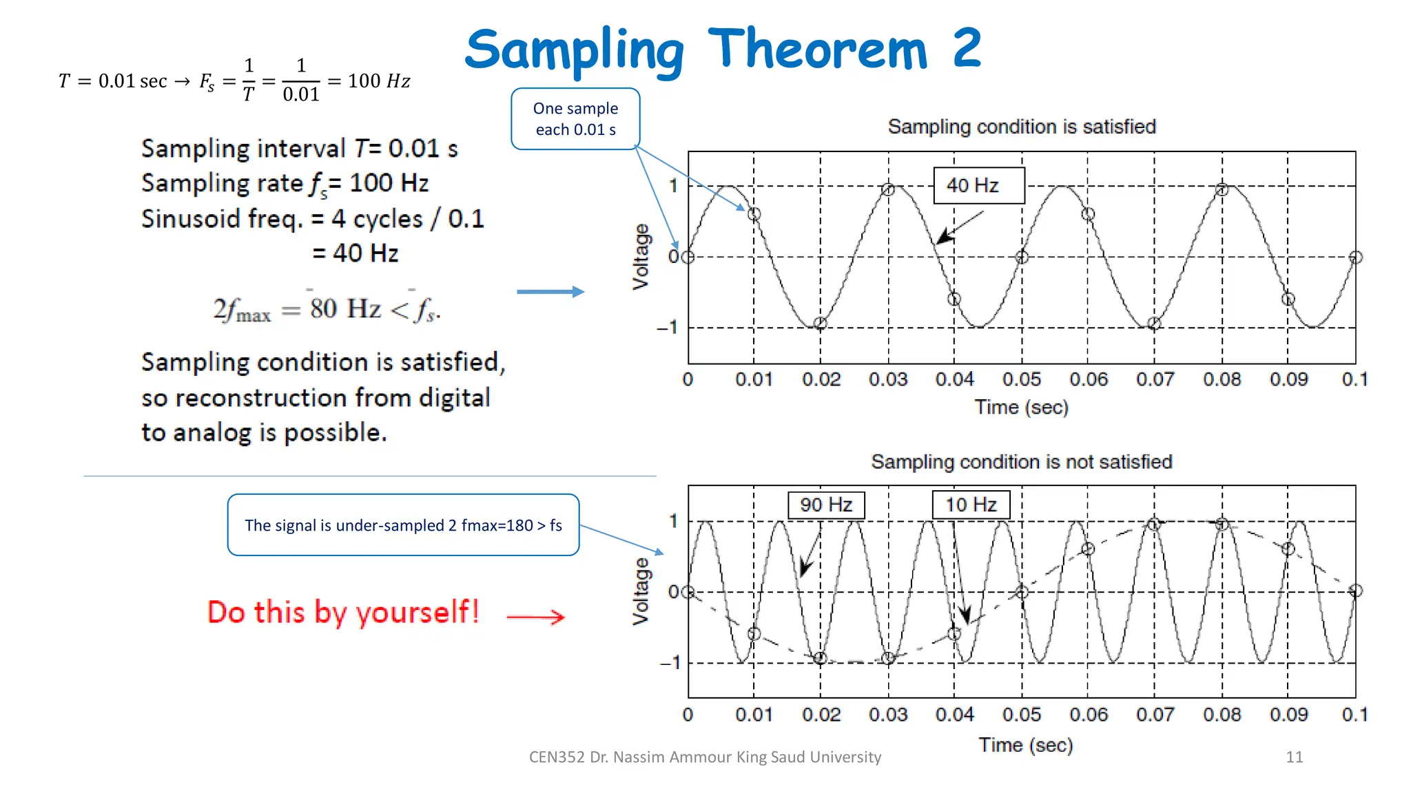
![Sampling Theorem 1
10
CEN352 Dr. Nassim Ammour King Saud University
• Question: Are the samples 𝑥[𝑛] sufficientto describe uniquely the original continuous-time signal and, if so, how
can 𝑥𝑐 [𝑡] be reconstructed from 𝑥[𝑛] ? An infinite number of signals can generate the same set of samples.
• Answer: The response lies in the frequency domain, in the relation between the spectra of 𝑥𝑐 [𝑡] and 𝑥[𝑛] .
different continuous-time signals with the same set of sample values](https://image.slidesharecdn.com/chap2sampling-240229043737-7ced4008/75/Signal-Sampling-and-signal-quantization-10-2048.jpg)


![Digital Signal Processing[ECEG-3171]-Ch1_L06](https://cdn.slidesharecdn.com/ss_thumbnails/dspl6ch2-180427094424-thumbnail.jpg?width=640&height=640&fit=bounds)


![Digital Signal Processing[ECEG-3171]-Ch1_L05](https://cdn.slidesharecdn.com/ss_thumbnails/dspl5ch2-180427094424-thumbnail.jpg?width=640&height=640&fit=bounds)