This paper presents the design and prototype implementation of the automation system that can be used two Arduino Nano with sensors. To demonstrate the effectiveness of this system, the devices such as LDR, temperature sensor, smoke sensor and motion sensor have been integrated with the automation system. In addition, the GSM and RFID modules are also used for security system. The functions of the sensors are to monitor and control the light, the room temperature and alarms. The main goal of the security system is GSM which is used to send the SMS alerts to the owner. Two Arduino Nano control sensors and relays that monitor a defined location and take action based on specified parameters like ambient light, temperature, etc. The microcontroller will send SMS to the owner if the sensors detect an abnormality. In addition, door lock security is developed by RFID module. In this paper, the presents of GSM module security system make more secure and reliable. Ma Naing | Ni Ni San Hlaing ""Arduino Based Smart Home Automation System"" Published in International Journal of Trend in Scientific Research and Development (ijtsrd), ISSN: 2456-6470, Volume-3 | Issue-4 , June 2019, URL: https://www.ijtsrd.com/papers/ijtsrd23719.pdf
Paper URL: https://www.ijtsrd.com/engineering/electronics-and-communication-engineering/23719/arduino-based-smart-home-automation-system/ma-naing
2. International Journal of Trend in Scientific Research and Development (IJTSRD) @ www.ijtsrd.com eISSN: 2456-6470
@ IJTSRD | Unique Paper ID - IJTSRD23719 | Volume – 3 | Issue – 4 | May-Jun 2019 Page: 277
system has the ability to perform the full responsibilities.
The programming software of the system is Arduino C
programming software. A program is text that user write
using a programming language that containsbehaviours that
need a processor to acquire. It basically creates a way of
handling inputs and producing outputs according to these
behaviours. It is often defined as a general purpose
programming language and is indeed one of the most used
languages of all times.20×4 I2C LCD and 16×4 I2C LCD are
used to show the condition of door, light, the value of
temperature and fire condition. 20×4 LCD has 20 columns
and 4 rows and 16×2 LCD has 16 columns and 2 rows. Both
LCD have I2C serial pin to connect with Arduino. LCD device
is connected with I2C device to reduce pin connection of
LCD. I2C device has SDA and SCL pin for serial
communication. The other pins are power supply pin and
ground pin. The I2C protocol involvesusingtwolines tosend
and receive data a serial clock pin (SCL) that the Arduino
board pulses at a regular interval, and a serialdatapin(SDA)
over which data is sent between the two devices. In the
sketch, LCD_I2C lcd(5,0) is written and “Mingalarpar” is
printed in here. “Welcome to Group II” is printed in columns
0 and row 1. In columns 2 and rows 2, “Home Automation”is
printed.
Fig.2: Sketch for LCD
“Light” is printed in row 3 and column 0 to show light
condition. If the LDR detects the decreasing of light level,
Arduino microcontroller turns on 12V LED. The output of
LDR is connected to the analog pin of Arduino Nano.
Fig.3: Sketch for LDR
To automatically switch LED bulb, relay is used. Arduino
send the signal to the input of relay and turn on the relay.
Digital pin of Arduino is used to send the signal to the relays.
The light condition is show in the 20×4 LCD. If the light level
is decreased, LCD show “Turn On.” at row 3 and column 11.
Else, LCD show “Turn Off”. PIR sensor is used for burglar
alarm system and it works at night. PIRfunctionis written as
Mo() in the night condition command. If PIR sensor detectsa
motion, GSM module send alarm SMS to the setting phone
number. For fire alarmfunction, LCDshow“SmokeDetected”
in row 1 and column 0. If Smoke sensor detects the smoke,
the signal is sent to the analog pin of Arduino. LCD show
“Fire Alarm” in columns 0 and rows 2.
Fig.4: Sketch for Smoke Sensor
Fig.5: Sketch for 16×2 LCD
“TEMP” is printed in row 0 and column 0 to show
temperature. “Door” is printed in rows 1 and columns 0. To
show the value of temperature in the LCD,
‘LCD.setCursor(10,0)” can be commanded in the sketch. So
LCD is show temperature value in row 10 and column 0. If
the room temperature is up to 30 Degree Celsius, Arduino
turn on the fan and show the temperature value on the LCD.
Else, Arduino turn off the fun.
Fig.6. Sketch for Temperature Sensor
3. International Journal of Trend in Scientific Research and Development (IJTSRD) @ www.ijtsrd.com eISSN: 2456-6470
@ IJTSRD | Unique Paper ID - IJTSRD23719 | Volume – 3 | Issue – 4 | May-Jun 2019 Page: 278
Fig.7: Inserting UID Number of the Tag to the Sketch
In these figure, receiving code is matched by Arduino with
store code. If the code is same, Arduino will send signal to
the servo motor and then open the door. And LCD shows the
door condition. If tag’s ID matches with the ID in the code,
the door will open automatically. It closes manually with
switch using internal pull-up function. Thereare20Kpull-up
resistors built into the Atmega chip that can be accessed
from software. These built-in pull-up resistors are accessed
by setting the pinMode() as INPUT_PULLUP. This effectively
inverts the behavior of the INPUT mode, where HIGH means
the servo is off, and LOW means the servo is on.
Fig.8: Sketch for Door Switch
SIM900A GSM Module
For the security system, the GSM sends text message based
on the sensors (PIR and Smoke sensors) used in this system.
If the PIR sensor gets any unusual movements, the user will
get a text message. This means that there is someone near
the house in absence of the user. The GSM also plays an
important role in fire alarming system with the help of
smoke sensor. When smoke is detected, the system sends
text message through GSM.
Fig.9: Program for Send Message Function
B. Implementation by Hardware
Arduino
NANO
Tx
Rx
RST
GND
D2
D3
D4
D5
D6
D7
D8
D9
D10
D11
D12
Vin
GND
RST
5V
A7
A6
A5
A4
A3
A2
A1
A0
REF
3V3
D13
GSM
SIM
900A
+
-
Tx
RFID
RC_522
SDA
SCK
MOSI
MISO
GND
RST
3.3V
PIR
Arduino
NANO
Tx
Rx
RST
GND
D2
D3
D4
D5
D6
D7
D8
D9
D10
D11
D12
Vin
GND
RST
5V
A7
A6
A5
A4
A3
A2
A1
A0
REF
3V3
D13
InverterBattery
+
+-
Solar pannel
5V
- +
- -
+
GND
AC to DC
power card
+
-
+
-
Servo
D
batton
LCD
2004
+
-SDA
SCL
Rx
2 Channel
Relay
LCD
2004
+
-
SDA
SCL
LDR
Smoke
Sensor
AC
Bulb
+
-
+
-
CMD Nc
Buzzer
LM 35
2 Channel
Relay
+ -CMD
Nc
Fan
-
+
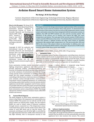
Fig.10: Overall Circuit Diagram of the system
Smart home automation system is designed with Arduino
Nano, sensors, sensor modules/shield, fan, bulb, alarm
system, door lock system. If the temperature sensor feels an
increase in room temperature, Arduino microcontroller
takes a necessary action like automatically turn the fun on
which work as air condition. If the flame sensor detects fire,
Arduino takes action like turn alarm system and sending
SMS to owner. If the LDR sensor feels a decrease the level of
light in the room, Arduino takes action like turnthebulb.PIR
sensor is used for burglar alarm system. For security door
lock system, RFID system and servo motor is used. The
movement of the curtains will depend on the requirementof
light which is measured with Light Dependent Resistor
(LDR).PIR Sensor (HC – SR501) is used for motion detection.
Through GSM module, microcontroller will send SMS text
message to the owner. This will ensure safety inside the
house with the help of PIR sensor.
IV. Results
After connecting and programming all the components, all
the components will be run by the whole system. All
modules and microcontroller are kept together with a lot of
wires. This part is the main center of the home automation
system. The sensors are placed at a suitable side of the room
as shown in Figure 11. Fan is turned ON or OFF using
temperature sensor .When temperature increases, the
current will flow and the relay switch turn ON the fan
automatically.
4. International Journal of Trend in Scientific Research and Development (IJTSRD) @ www.ijtsrd.com eISSN: 2456-6470
@ IJTSRD | Unique Paper ID - IJTSRD23719 | Volume – 3 | Issue – 4 | May-Jun 2019 Page: 279
Fig.11: Components Installation
Light is turned ON or OFF, using LDR sensor (Figure 12).
When the LDR senses the darkness, the Arduino commands
the relay switch and which turn on the bulb. With the helpof
PIR sensor, the presence of a person is detected and the
buzzer rings automatically.Then,theGSMmodulesends SMS
alerts to the owner.LCD shows door condition, light
condition, temperature value and fire condition. At the
normal condition, the 20×4 LCD shows“Mingalarpar”forthe
first row, “Welcome to Group II” for the second row, “Home
Automation” for the third row and “Light Turn Off” for the
fourth row. The 16×2 LCD display shows “Temp 30.00” for
the first row and “Door Lock” for the second row. The two
LCD displays are shown in figure 13. Servo motor isinstalled
on the home frame with the door to open or close the door
shown in figure 15.For SMS alarm system, GSM SIM 900A is
used to send SMS message to the owner shown in figure 16.
(a)
(b)
Fig12: (a) Light (LED) OFF, (b) Light (LED) ON
(a)
(b)
Fig.13: Testing of (a) 20×4 LCD, (b) 16×2 LCD
(a)
(b)
Fig.14: (a) Door Closed Condition, (b) Door Opened
Condition
5. International Journal of Trend in Scientific Research and Development (IJTSRD) @ www.ijtsrd.com eISSN: 2456-6470
@ IJTSRD | Unique Paper ID - IJTSRD23719 | Volume – 3 | Issue – 4 | May-Jun 2019 Page: 280
Fig.15: Testing of RFID System
Fig.16: SMS Alarm
V. Discussion
This paper is discussed about the development of
automation system byArduinoTheautomation systemis low
cost and user friendly. In future, some devices are more
reliable, faster and cheaper. The componentscan bechanged
with the latest device but it should have the right software
and the right driver. All tasks of this system are done
successfully. The limitations in time and expenses but it will
serve as basis of latest AI systems as that of western
countries. Almost all scientific and latest technologies have
both good and bad sides. This type of work inspires the user
s to do better for our country. Smart Technologyisablessing
for our country. The bad consequences are avoided and it is
used for the betterment. This paper is emphasized
theoretical aspects of design and construction automation
system.
VI. Conclusion
In this paper a design and implementation concept for a
smart home automation system based on Arduino
microcontroller board. Sensors are connected to the
microcontroller board. The home appliances can be
monitored, controlled and accessed automatically in
response to any signals came from related sensors. The
system relies on power supply. If power supply fails, the
connection will be halted and SMS alarm functions will be
stopped. The security system is powered by another power
source for security safety.Withoutsecuritysystem,itdoesn’t
complete the whole system. The porposed system is shown
to be a simple, cost effective and flexible.
VII. REFERENCES
[1] Shatha J. Alghamdi, Lamiaa A. Elrefaei, "Dynamic User
Verification Using Touch Keystroke Based on Medians
Vector Proximity", Computational Intelligence
Communication, (2015).
[2] TziporaHalevi, HaoyuLi,DiMa,NiteshSaxena,Jonathan
Voris, Tuo Xiang, "Context Aware Defenses to RFID
Unauthorized Reading and Relay Attacks", Emerging
Topics in Computing IEEE Transactions on, (2009).
[3] Raphael C.-W. Phan, Jean-Philippe Aumasson, "Next
generation networks: Human-aided and privacy-
driven", Innovations in NGN: Future Network and
Services, (2008).
[4] RobertLarkins, Michael Mayo, "Adaptive Feature
Thresholding for off-line signature verification", Image
and Vision Computing New Zealand, (2008).
[5] Tieyan Li, "Employing Lightweight Primitives on Low-
Cost RFID Tags for Authentication", Vehicular
Technology Conference (2008).
[6] J. Fazenda, D. Santos, P. Correia, "Using Gait to
Recognize People", Computer as a Tool, (2005).