
Recommended
More Related Content
Similar to ir sensor.docx
Similar to ir sensor.docx (20)
Recently uploaded
Recently uploaded (20)
ir sensor.docx
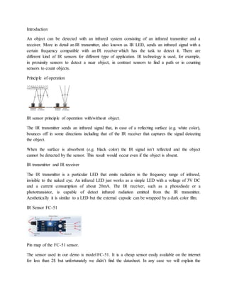
- 1. Introduction An object can be detected with an infrared system consisting of an infrared transmitter and a receiver. More in detail an IR transmitter, also known as IR LED, sends an infrared signal with a certain frequency compatible with an IR receiver which has the task to detect it. There are different kind of IR sensors for different type of application. IR technology is used, for example, in proximity sensors to detect a near object, in contrast sensors to find a path or in counting sensors to count objects. Principle of operation IR sensor principle of operation with/without object. The IR transmitter sends an infrared signal that, in case of a reflecting surface (e.g. white color), bounces off in some directions including that of the IR receiver that captures the signal detecting the object. When the surface is absorbent (e.g. black color) the IR signal isn’t reflected and the object cannot be detected by the sensor. This result would occur even if the object is absent. IR transmitter and IR receiver The IR transmitter is a particular LED that emits radiation in the frequency range of infrared, invisible to the naked eye. An infrared LED just works as a simple LED with a voltage of 3V DC and a current consumption of about 20mA. The IR receiver, such as a photodiode or a phototransistor, is capable of detect infrared radiation emitted from the IR transmitter. Aesthetically it is similar to a LED but the external capsule can be wrapped by a dark color film. IR Sensor FC-51 Pin map of the FC-51 sensor. The sensor used in our demo is model FC-51. It is a cheap sensor easily available on the internet for less than 2$ but unfortunately we didn’t find the datasheet. In any case we will explain the
- 2. operation of the related electronic circuit and subsequently implement some demo to test its functioning. Pinout and schematic This is the schematic of the IR sensor FC-51. The package has three connection pins: Vcc to the power supply 3-5V DC; Gnd to the ground reference; Out for the digital output signal of the sensor. This sensor detects objects at a distance in range between 2~30cm. With the potentiometer you can calibrate the sensitivity according to the application and environmental conditions (e.g. brightness). The IC LM393 is an open-collector voltage comparator which provides an output if there is a pull-up R between the output of the IC (DO) and the power supply Vcc (R=10KΩ). The output DO is: high if the object is not detected; low if the object is detected. Proposed explained Test IR sensor FC-51 with serial terminal
- 3. Demo 1 schematic. In the first demo, through the connection between the Arduino serial port and the PC, we will read about the detection of the object. Lets take a look to steps required by this demo: We connect the OUT pin of the sensor to digital pin 2 of Arduino called IR. The setup() function is performed only once before the main loop. We insert here the initialization code which enables serial port Arduino and sets the digital pin 2 as input. loop() is the main function and is cyclically repeated until you turn off the Arduino board. We convert in C language the operation of the electronic circuit analyzed before. We save in the variable detection the value taken from the pin IR with the specific function digitalRead, if the value is low there is an object otherwise there isn’t.
- 4. IR InfraredObstacleAvoidanceSensorWith Arduino There have been many innovations in technology that have changed the world. One of them is Infrared Technology.Nowadays, Infrared technology has a wide variety of wireless applications mostly in object sensingand remote controls. Today we will talk about Infrared Obstacle Avoidance Sensor Module, it's working, and how to connect it with Arduino. Infrared IR Sensor Obstacle Avoidance Sensor board is an inexpensive solution to avoidance detection for robotics, smart car, and other electronicuses. Infrared Obstacle Sensor Module has a built-in IR transmitter and IR receiver that sends out IR energy and looks for
- 5. reflectedIR energy to detect the presence of any obstacle in front of the sensormodule. The module has an onboard potentiometerthat lets users adjust the detection range. The sensorhas a very good and stable response even in ambient light or in complete darkness. The Obstacle Avoidance Sensors usually come in two types — with 3 and 4 pins. WORKING PRINCIPLE The IR transmittersends an infrared signal that, in case of a reflecting surface (e.g. white color), bounces off in some directions includingthat of the IR receiver that captures the signal detecting the object. When the surface is absorbent the IR signal isn’t reflectedand the object cannot be detected by the sensor.This result would occur even if the object is absent.
- 6. The module has 3 pins — Vcc, GND, and the output. We also have 2 LEDs, one is for the power that is it turns ON when it is connectedto the power. The otheris for obstacle detection. Connections 1. Connect the Vcc of the Sensor Module to the Vcc of Arduino Board 2. Connect GND of the SensorModule to the GND of the Arduino Board. 3. Connect the output pin of the sensormodule to pin 7 of the Arduino Board. 4. When the Obstacle Avoidance Sensor detects an obstacle, the LED will be on. Otherwise,it will be off.
- 8. Obstacle Detector By IR Sensor with Arduino We all have sure observed that our phone display turns off during phone calls when we put it near our ears. So, do you ever wonder how does this happen??? It is not a hi-tech thing but a simple IR sensor to detect the obstacle near the phone we are also making the same project in this article with IR sensor with Arduino. Also, in many other devices like toy helicopters which fly if we put our hand under them, or any drones that can fly and land automatically. All these devices use IR sensor with arduino to detect obstacles or short distances. Many other versions of ir distance sensorArduino and kits are available in the market for a good price but we are here to encourage you all to DIY yourself the simple things with the help of basic components like Arduino, led, buzzer, and a few others.
- 9. How to make Obstacle Detector By IR Sensor with Arduino: – Components used in this are as always very basic ones, an Arduino Uno or any other microcontroller you have, an LED, a buzzer, and a few others. There are basic, good, and also arrays of IR sensors available in the market for various purposes but the use and working of each are the same the difference in array in simple one it that in the array you get the average value of 4 to 5 IR sensors to get more error-free value, this we’ll discuss some other day in the future but today let’s switch over to our topic i.e., IR SENSOR with Arduino. So as before it is the most common sensor among beginners and very interesting projects can be designed using this like line follower robots, Obstacle avoiding robots, and many others. IR sensor contains two LED’s one is white which is an Infrared Light transmitter and another one is Black which is an Infrared Light receiver. As the name suggests their work is so obvious. The sensor is built out of LM358 IC is similar to LM393 IC from which I think you all must be familiar with and know a bit about this IC.
- 10. The sensor also has an onboard power led and also an onboard Status led which will blink whenever the sensor detects or receives back the infrared light emitted by infrared emitter. The sensor gives both digital and analog output. The difference between the two is very simple in digital output only high or low means either 1 or 0 is transmitted to a microcontroller but in the analog signal, a wide range of values from 0 to 1023 is transmitted to the microcontroller which relates to the intensity of light received by the receiver. You can also slightly trim the values of the IR sensor with Arduino with the help of a potentiometer provided on the sensor PCB. *NOTE: – THE SENSOR VALUES DEPEND ON THE DISTANCE OF THE EMITTED LIGHT, REFLECTING SURFACE, AND RECEIVER. ALSO, BLACK OR DARK SURFACE CAN ABSORB ALL THE LIGHT INCLUDING INFRARED SO THE SENSOR WON’T WORK ON THOSE SURFACES. IR Sensor with Arduino
- 11. SCHEMATIC DIAGRAM/ IR Sensor with Arduino Circuit:- FEATURES AND APPLICATIONS IR Sensor with Arduino: – The range is a short but appropriate value Easy to use and fix Adjustable value Low price Can be used in various distance or obstacle-related projects. SENSOR SPECIFICATIONS: Components Required for IR Sensor with Arduino Arduino UNO USB cable for uploading the code IR sensor Buzzer and an LED Jumper wires and a breadboard 220-ohm resistor IR SENSOR WITH ARDUINO CIRCUIT DIAGRAM: Circuit diagram for digital output of IR Sensor with Arduino
- 12. Arduino UNO IR Sensor ( +5V ) VCC GND GND D2 Pin OUT Pin Arduino UNO Buzzer D7 Pin Positive GND Negative
- 13. Arduino LED R 220 Ohm Resistor D6 Pin Anode Pin GND Terminal 1 Cathode Pin Terminal 2 Circuit diagram for analog output of IR Sensor with Arduino connection table for IR Sensor with Arduino Arduino UNO IR Sensor
- 14. ( +5V ) VCC GND GND D2 Pin OUT Pin Arduino UNO Buzzer A0 Pin Positive GND Negative Arduino LED R 220 Ohm Resistor D6 Pin Anode Pin GND Terminal 1 Cathode Pin Terminal 2 the above-given circuit diagram is only for the LED notification. when the IR Sensor with Arduino detects anything it will notify by the LED. and the next image is for the Sound notification we will use the buzzer in that circuit. First, take the power lines onto the breadboard from the microcontroller VCC/5v–>+ line and GND–> – line. Then connect the sensor to the breadboard and connect power to the sensor from powerlines using jumper wires. Now connect D0 PIN OF SENSOR TO MICROCONTROLLER DIGITAL PIN 2.
- 15. Now connect led to the breadboard + to digital pin 13 of Arduino and – to and in series with 220- ohm resistor. Moreover, we can also use it in analog mode for that simply connect the A0 pin of the sensor to pin A0 of the microcontroller. Enhance this version by adding a buzzer to it also like in the above diagram. Connect -live of the buzzer to GND on a breadboard, and +tive to 5V on a breadboard. IR Sensor with Arduino Code:- // IR Sensor with Arduino //put this code in the ide of arduino from this line ( FOR digital output) //Digital code // Techatronic.com int val = 0 ;
- 16. void setup() { Serial.begin(9600); // sensor buart rate pinMode(2,INPUT); // IR sensor output pin connected pinMode(6,OUTPUT); // LED pinMode(7,OUTPUT); // BUZZER } void loop() { val = digitalRead(2); // IR sensor output pin connected Serial.println(val); // see the value in serial monitor in Arduino IDE delay(500); if(val == 1 ) { digitalWrite(6,HIGH); // LED ON digitalWrite(7,HIGH); // BUZZER ON } else
- 17. { digitalWrite(6,LOW); // LED OFF digitalWrite(7,LOW); // BUZZER OFF } } // ir sensor with arduino analog value // IR Sensor with Arduino // Techatronic.com void setup() { Serial.begin(9600); // sensor baud rate pinMode(6,OUTPUT); // LED pinMode(7,OUTPUT); // BUZZER } void loop() { int s1=analogRead(A0); //ANALOG PIN FOR SENSOR Serial.println(s1); // see the value in serial monitor in Arduino IDE
- 18. delay(100); if(s1>200 ) { digitalWrite(6,HIGH); // LED ON digitalWrite(7,HIGH); // BUZZER ON } else { digitalWrite(6,LOW); // LED OFF digitalWrite(7,LOW); // BUZZER OFF } } WORKING of ir sensor with arduino : – As the code in the setup section, we define the pin along with the type to which the sensor is connected also we initialize the pin and type for led and buzzer. In the loop section, we read the digital value on pin 2 of the microcontroller and according to the value, we apply conditions either 1 or 0 to turn the led and buzzer on or off. In the analog code in the loop section, we read the analog value i.e., 0-1023 values on pin A0 and according to the value of 200 or more, we turn led and buzzer on or off.