2. Exp Astron
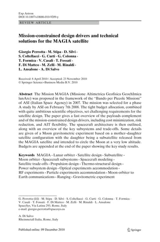
Fig. 1 Key elements of the MAGIA Mission
1 MAGIA mission
The MAGIA mission, whose key elements are shown in Fig. 1, has the
following scientific objectives:
– Detailed study of the internal structure of the Moon through its gravity;
– Study of the polar and subpolar regions in terms of their morphology and
mineralogy;
– Study of the lunar exosphere and radioactive environment;
The mission intended also to contribute to the fundamental physics via mea-surements
of the gravitational redshift, and to perform test in view of the
second-generation lunar laser ranging.
The scientific mission was implemented with a suite of instruments and
experiments as shown in Table 1.
A total payload mass plus control electronics, thermal control and harness
of less than 60 kg results, which is fairly credible since the most massive units
Table 1 Payload complement to accomplish the scientific mission
Instrument Acronym Mass (kg)
Spectrometer context camera CAM-SIR 11
High resolution camera CARISMA 4
Radar altimeter and radiometer RAR 9
Gravitometric experiment dual accelerometer ISA 6.1 (+6.1 in subsatellite)
Neutral particle detector ALENA 1
Particles spectrometer RADIO 0.3 (est.)
CCR array VESPUCCI 3
CCR-MoonLight MoonLight-P 1.2
Radio science Radio science X- and S-band RF links
3. Exp Astron
Table 2 Orbit parameters for
the lunar mapping orbit
Lunar mapping orbit
Semi-major axis 1,838 km
Eccentricity 0.00675
Inclination 89.99
Argument of perigee 270◦
Orbital period 2 h
are already existing or are derived by similarity to already-flown ones. With
the exception of the Radar Altimeter and Radiometer and the MAGIA-borne
accelerometer (the other accelerometer is installed on board the releaseable
subsatellite) all instruments are housed in a thermally controlled module
mechanically decoupled from the rest of the spacecraft.
The Earth–Moon transfer is a dimensioning space segment factor due to
the propulsion requirements.Different lunar transfers were analyzed including
Hohmann-like and variants of the Weak Stability Boundary trajectories. A
Hohmann transfer was selected for its simplicity and short time duration.
The two launchers taken into consideration, as requested by the Customer,
are Vega and Soyuz/Fregat, which represent European small and medium
class options in terms of capability and cost. The Soyuz/Fregat launcher
resulted to be fully compatible with the mission and transfer requirements and
was therefore chosen, allowing a direct lunar injection, while minimizing the
propellant mass to be embarked.
A circularization maneuver around the Moon, to insert the spacecraft into
the operational orbit, is required by lowering the orbit altitude with respect to
the arrival conditions. A polar frozen low lunar orbit (LLO) was selected for
a preliminary characterization from an operational point of view (e.g., lunar
coverage, ground visibility etc.); the orbital parameters are shown in Table 2.
An uncontrolled LLO, leaving the orbital plane essentially unchanged in
an inertial frame, allows in principle a complete coverage of the lunar surface
during a sidereal month. TheMoon advances about 15◦/day along its orbit, and
within this time span, a satellite injected on a 100 km orbit completes about 12
orbits around the Moon. As a consequence, the angular separation between
two subsequent orbits in a frame rotating with the Moon is of the order of 1◦.
The maximum duration of spacecraft routine solar eclipses lasts about
45 min, roughly corresponding to 40% of the orbital period; total lunar eclipses
represent the worst-case period for the spacecraft without sunlight.
Two distinct mission phases are foreseen: the first devoted to lunar mapping
and imaging and the second to the gravity experiment. Two slightly different
Table 3 Orbital parameters
for the gravity experiment
Gravimetric experiment orbit
Semi-major axis 1,798 km
Eccentricity 0.00675
Inclination 93.00
Argument of perigee 270◦
Orbital period 2 h
4. Exp Astron
Table 4 Earth–Moon
transfer velocity increments
requirement
Maneuver (s) V (km/s)
LOI (Hohmann transfer) 0.8
Lunar imaging phase orbital control 0.070
Orbital transfer 0.093
Safety margin (+5%) 0.050
Total 1.012
nominal orbits have been respectively selected for the two phases. For the
6 months of mapping and imaging, it is highly desirable to have a polar
orbit, since it guarantees the best coverage of the entire lunar surface. The
experiment requires that the satellite altitude be maintained within a range
of 100 ± 30 km. Therefore, orbital correction maneuvers are preliminary
planned every 40 days to restore the eccentricity to its nominal value. Since the
duration of this mission phase is fixed at 6 months, five correction maneuvers
are needed. Each maneuver consists of two burns for a total of 14 m/s. The
total Delta-V necessary for maintaining the orbit inside the nominal box for
this phase is then 70 m/s.
At the end of the lunar mapping phase, the spacecraft must be transferred
to the gravimetric nominal orbit (Table 3), by changing orbit semi-major axis
and inclination, required to cope with scientific experiment requirements. The
latter maneuver, to achieve an inclination change of about 3◦, is the most
expensive, requiring a Delta-V of about 85 m/s; a total Delta-V of 93 m/s
is estimated for the overall orbital transfer, including the semi-major axis
trimming.
The orbit control strategy during the gravity experiment phase is compli-cated
by the presence of a releasable subsatellite, which has no maneuvering
capability. The gravitometric experiment requires at least 1 month of opera-tions,
at a mean radius of 1,798 km, though a longer mission duration of up to
3 months was considered.
The total velocity increment for the overall mission that must be provided
by the spacecraft propulsion system, is summarized in Table 4. Let us stress
that the first maneuver to inject the spacecraft into the Lunar Transfer Orbit
is assumed to be performed by the launcher. To accomplish all complex
mission maneuvers, a double propulsion system was baselined, including both
a hydrazine system for spacecraft orbit transfer and reorientation, and a cold-gas
one for attitude control tasks.
2 Spacecraft design approach
The spacecraft architecture consists of three functionally, physically and tech-nologically
independent assemblies:
Propulsion module; Platform (or Service) module; Payload module
5. Exp Astron
The sum of these three modules can be enveloped by a parallelepiped with
dimensions: 700 × 1,400 × 2,050 mm.
The propulsion module hosts both a hydrazine-based main propulsion
system and a cold-gas based auxiliary propulsion system. It also hosts the
subsatellite along with its release system.
The platform (or Service) module hosts the majority of the electronic
subsystems, with the exception of the star sensors which are integrated in
the payload module and of the X-band high-gain antenna (HGA) which is
accommodated on the upper part of the payload module as well.
The payload module accommodates most payloads—with the exception of
the radar payload, a high sensitivity accelerometer (ISA), and a high stability
clock. The payload module has been carefully designed to meet the tight
operating temperature limits of the payload equipments.
The spacecraft design was conceived to be largely built around previously
qualified items, when available, or on COTS further subjected to delta-tests
when their heritage or status did not meet minimum quality levels considered
adequate within the cost limitations of the Programme.
A prototype approach was also baselined, since most units were derived
from already-flown ones, with the exception of new instruments that had to be
subjected to a qualification campaign with somewhat reduced severity levels,
however.
3 Spacecraft structure
The spacecraft structure encompasses all three modules using different tech-nologies
matched to the operational requirements of each. More specifically,
the propulsion module, shown in Fig. 2, is an open-truss structure of carbon-
Fig. 2 Propulsion module,
tanks and subsatellite
6. Exp Astron
Fig. 3 Service module,
interior
fiber-reinforced plastic (CFRP) tubular elements connected with high-strength
aluminum alloy joints.
It carries the tanks of the propulsion system (mono-methyl hydrazine fuel
and a pressurant) and the Attitude Orbit Control Subsystem thrusters, the
propulsion system harness (valves, tubes etc.) and the subsatellite deployer (a
closed, box-shaped, aluminum alloy sandwich structure carrying the subsatel-lite
for the gravitometric experiment).
The propulsion module is connected to the service module by high-strength
screws permitting a smooth transfer of loads. The service module, shown
in Fig. 3, is a closed aluminum alloy sandwich structure with high-strength
aluminum frame carrying longitudinal and lateral loads. The lateral sand-wich
panels are integrated with aluminum-machined plates with stiffeners to
adequately support the electronic boxes accommodated on the panel which
contribute to the overall satellite stiffness. The interface with the propulsion
module and the top panel—which interfaces with the payload module—are
thick core sandwich panels to meet the requirements of dimensional stability.
The Service module carries most of the electronic boxes including the Radar
Fig. 4 Payload module,
interior
7. Exp Astron
Fig. 5 MAGIA spacecraft
structure in three modules:
launch configuration
payload; and—along with the propulsion module structure—supports the large
lightweight sandwich solar panels via a truss structure made of small-section
CFRP tubular elements. The payload module, illustrated in Fig. 4, is a closed
box made by sandwich structural panels carrying optical payloads and star
trackers. The base panel is a dedicated optical bench in order to have a
common stiff interface and to permit the correct alignment between different
instruments optics and star sensors.
The mechanical connection with the service module is designed in order to
reduce the thermo-elastic deformations coming from the orbital thermal loads.
The MAGIA satellite, in both its launch and in-orbit configurations, is
shown in Figs. 5 and 6. A detailed Finite Element Model was developed to
perform both static and dynamic analyses of each module and of the full
spacecraft. A modal frequencies analysis was performed along the X-axis, as
themost representative, to obtainmodal participation mass factors. The results
indicate compliance with the launcher (Fregat/Soyuz) frequency (20 Hz on
lateral axes). Besides, a rapid overview of the modal analysis enabled to
pinpoint that the lower side of the elements of the propulsion module truss are
the more stressed elements. Detailed static analyses were then performed on
Fig. 6 MAGIA spacecraft:
in-orbit configuration with
two solar panels deployed
8. Exp Astron
each module to better assess the structure criticalities. Several areas requiring
local improvements were thus identified and characterized.
4 Propulsion subsystem
Three design alternatives were considered:
(a) Independent hydrazine and cold-gas (N2) propulsion systems. The pri-mary
propulsion system operates in a pressurized mode, requiring a
helium-filled pressurant tank; and a separate N2 auxiliary propulsion
system operating in a blow-down mode, the N2 being contained, at high
pressure, in a third tank;
(b) A hydrazine/nitrogen propulsion system with two interconnected tanks,
one containing hydrazine and the other compressed nitrogen acting as
a pressurant for the hydrazine system while operating in a blow-down
mode for the cold-gas, auxiliary, propulsion system;
(c) An all-hydrazine propulsion system operating in a blow-down mode for
both the primary and auxiliary propulsion system.
Conservatively, the first configuration (a), shown in Fig. 7, with three tanks
and two independent propulsion systems, was selected as a baseline, which
is largely based on commercial, space-qualified components: tanks from
N2
fill/drain
valve
pressure
transducer
filter
pressure
regulator
pressure
transducer
relief
valve
thrusters thrusters
Fig. 7 Pressurized hydrazine for orbit control (on the right); and cold nitrogen propulsion system,
operating in a blow-down mode, (on the left) for attitude control
9. Exp Astron
PSI/ATK or ARDE’, hydrazine thrusters from EADS, valves and cold-gas
thrusters from Moog or Encore.
Since the orbital maneuvers require repointing and will be implemented
piecewise, a commercial, qualified, thrust motor (EADS CHT 20) providing
20 N thrust is employed. About 140 kg of hydrazine will be stored in a quite
large elliptical tank (type 80420-1 from ATK/PSI). A pressurized, helium-based,
pressurant tank is used to keep high the motor Isp even when the
Hydrazine tank will be almost depleted. The pressurant is contained in a
titanium spherical tank (type 80202-1 from ATK/PSI) also hosted in the
Propulsion module.
The propellant tankage will be capable of providing the velocity increment
of Table 3 for a satellite dry mass of 232 kg, which represented a target mass
for the feasibility study phase.
The cold-gas propulsion system is used for reaction wheels desaturation, as
well as to support spacecraft reorientation pre-post hydrazine engine firing.
The N2 tank (a PSI/ATK type 80345-1) is sized to accommodate 5 kg of N2
at high pressure, and will operate in a blow-down mode. The cold-gas space-qualified
commercial thrusters will be in number of 8, in two quadruplets of
four thrusters each. The thrusters will be characterized by a thrust in the 20- to
50-mN range and an Isp around 50 to 60 s. The thruster can be from Moog or
other space-qualified microthrusters suppliers.
The computed dry mass of the propulsion subsystems amounts to 33 kg,
excluding the structure supporting the various components.
5 Power subsystem
The configuration of the solar array is quite unconventional due to several
reasons: the time evolution of the satellite orbit with respect to the Sun; the
nadir-pointing satellite attitude in a Moon orbit; the payloads duty cycles;
and the requirement for an unobstructed field of view for heat dissipation
Fig. 8 Solar array geometry
10. Exp Astron
Fig. 9 Solar array concept
by radiation. The solar array dimensions result from the combination of the
above factors. During the study, several solar array geometries were analyzed,
starting from that schematically shown in Fig. 8 which gave rise to many other
variants, the last of which is conceptually shown in Fig. 9.
The rationale for the configuration shown in Fig. 9 is the need for rejecting
heat from the sides of the platform module which is densely populated with
power dissipating electronic units while retaining the total solar array area and
shape of the initial configuration.
During launch, the in-orbit deployable panels will be restrained by means of
releasable double clamps. Accordingly, there will be six identical solar panels
each including 22 strings in parallel of 10 cells in series each, for a nominal
voltage around 26 V at Tamb (1,320 cells in total).
The solar array is thus composed of four body-fixed panels—two on the
dorsal side and two lateral panels, canted at 22◦w.r.t. the vertical—and two
in-orbit deployable panels. The fixed dorsal and lateral panels serve also to
block the Sun rays from reaching the propulsion tanks; while the two in-orbit
deployable panels, also canted by about 22◦ with respect to the local vertical,
are deployed to allow the platform module sides to radiate heat towards free
space.
High-efficiency, triple-junction, GaAs cells with an efficiency of 28% will
be used, with dimension of 80 × 40 mm and a space of 2 mm between any two
adjacent cells. A lower cell efficiency of 26%—leading to a considerable cost
saving—might become feasible by reducing the satellite and payloads power
demand. In the baseline each string of the Solar Array will have 10 cells (26
Voc at Tamb and 31.5 Voc at −75◦C, BOL) and 22 strings in parallel. In total,
there will be six panels all identical with dimensions of 924 × 820 mm.
A simulator has been developed in Matlab to analyze, as indicated in
Fig. 10, the generation of electric power from solar panels depending on the
11. Exp Astron
Fig. 10 A Matlab simulated
analysis of the generation of
electric power from solar
panels
position along the Moon orbit and the Sun vector incidence angle. The power
consumption along the orbit is also simulated; therefore the charge–discharge
of the battery is taken into account. The following relevant parameters were
computed:
– Average power generation = 622.6W
– Maximum power generation = 933.9 (lat 0◦/long 0◦)
The battery is based on a Li-ion technology which has achieved a fair
maturity stage. The battery is sized for a nameplate capacity of 1,000 Wh;
it is planned to drain energy from the battery up to a d.o.d. between 20%
and 25%, although the technology could well support d.o.d larger than this
throughout the about 3,300 charge–discharge cycles corresponding to a nom-inal
9 months mission duration. The Electric Power management implements
a semi-regulated bus architecture. In sunlight, a peak power tracking logic is
active to better adapt the variable load to the voltage–current characteristics
of the solar array. The battery charge circuit adapts the semi-regulated bus to
the voltage–current regime required by the Li-ion battery. In eclipse the bus is
fed by the unregulated voltage from the discharging battery.
6 Thermal control subsystem
The first priority was to optimize the spacecraft thermal control during the
nominal Moon mission. Several iterations were performed: the approach
finally adopted was also capable of supporting the spacecraft operations in
its parking orbit and throughout the Earth–Moon transfer phase. The basic
approach was to strive to achieve average Payload module temperatures lower
12. Exp Astron
Fig. 11 View of body-fixed
and in-orbit deployed solar
panels vs lateral Service
module surfaces
than those of the Service module, while keeping the propulsion subsystem
components well within their safe operating temperature range.
To achieve this result we have maximized the radiative surfaces of the
payload module and minimized the thermal exchange between payload and
platform modules. To maintain the Service module temperatures within the
hosted equipments allowed temperatures, we have chosen to in-orbit deploy
two of the six solar panels in order to maximize the radiation into free space of
the two side panels of the Service module (panels 8 and 9 of Figs. 11 and 12).
Besides, we have positioned four of the six solar panels in such a way to
shield the propulsion components (mainly the hydrazine, He and N2 tanks)
from the Sun rays. All tanks were also wrapped with multi-layer insulation
(MLI). Two of the four solar array panels used to shield the propulsion
Fig. 12 View of tanks of the
Propulsion module vs Service
module and solar panels
(fixed dorsal and deployed
lateral)
13. Exp Astron
Fig. 13 Units inside the
Service Module
module from the Sun rays are canted by 22◦ in order both to improve their
energy collecting efficiency as well as to improve their heat radiation capability
towards free space, at least during portions of the Moon orbit.
In Figs. 13 and 14, the radiating surfaces are green-colored, the contact areas
are in red. To improve the thermal conductivity we used a thermal filler CHO-THERM
1671 throughout. To thermally isolate units from the baseplate, we
used thermal washers with low thermal conductivity values.
This first optimization resulted in absorptivity/emissivity values pictorially
shown in Figs. 15, 16, and 17. We have also used four thermal straps (Amoco
P100 Carbon fiber. Radius = 5 mm, length = 20 mm) to connect solar panel
Y+ to service module faces Z+ and Z− (for the axes see Fig. 11). The straps
are placed inside the beams that link the service module to the solar panel.
It was indeed necessary to lower the temperature of Service module to
bring a few critical units (e.g., the high sensitivity accelerometer) within their
specified operating temperature range. Besides, we found necessary to lower
the temperature of the face Z+, facing the payload face Z−, to reduce the heat
flux. We thus achieved a doubly positive result: a strong reduction of the solar
panel gradients and of the heat flux towards the payload module.
Fig. 14 Units inside the
Payload module
15. Exp Astron
Table 5 Coatings and
materials eventually used for
MAGIA thermal control
optimization
External surface Internal surface
Payload:
FACE X+ (5) OSR 146434 Black Paint
FACE X− (2) OSR 146434 Black Paint
FACE Y+ (3) OSR 146434 Black Paint
FACE Y− (4) MLI 20 layers Black Paint
FACE Z+ (1) OSR 146434 Black Paint
FACE Z− (6) MLI 10 layers Black Paint
Propulsion:
Tank Hydrazine (20) MLI 10 layers
Tank He (21) MLI 10 layers
Tank N2 (22) MLI 10 layers
4 long beam (18) Black Paint Black Paint
8 short beam (19) Black Paint Black Paint
Platform:
FACE X+ (9) White Paint Black Paint
FACE X− (8) White Paint Black Paint
FACE Y+ (10) White Paint Black Paint
FACE Y− (12) MLI 10 layers Black Paint
FACE Z+ (7) Kapton, aluminized Black Paint
FACE Z− (11) White Paint Black Paint
Solar Y (13) Solar cell Black Paint
Solar X+ (14,16) Solar cell Black Paint
Solar X− (15,17) Solar cell Black Paint
The same strategy was followed to meet the propulsion tanks temperature
requirements. Indeed, we used two straps (length = 40 mm, radius = 5 mm)
that, like the previous ones, are placed inside the beam linking the solar panel
to the propulsion module structure.
As a result of extensive trade-offs, materials and coatings used for internal
and external surfaces are shown in Table 5. The simulation results, relevant
to the Moon-orbiting phase, show, in Figs. 18 and 19, that all equipment
remain within the operating or storage temperature ranges, depending on their
operative status. However, to achieve good results, it was necessary to use
heaters in a selective way, consuming between 5 and 30 W DC power from
the spacecraft bus.
Fig. 18 External panels temperatures with Sun rays in the Y–Z plane
16. Exp Astron
Fig. 19 External panels temperatures with the Sun rays hitting the spacecraft laterally (i.e, in the
X–Z plane)
Besides, very preliminary analyses showed that, during the transfer orbit,
the temperatures go to the lower limits. This might require an increase of the
DC power drain by heaters or else a further optimization of materials and
coatings to also take into account the detail requirements of the few equipment
that must operate also during the transfer orbit.
7 Attitude and orbit determination and control
The satellite must determine its attitude in three axes with an accuracy not
worse than: 0.01◦ at 3 sigma. The following sensors are envisaged:
– High accuracy star sensors: two pointing towards different directions. The
intrinsic accuracy of the star sensor is of the order of: 0.01◦
– Sun sensors of medium accuracy. These sensor are mainly used in the safe
mode and, if cooperating with the GPS receiver, supports the orbit resti-tution
on board as an aid to implement autonomous or semi-autonomous
navigation;
– Three-axis rate gyros. These serve to stabilize the desired pointing direc-tion
against disturbances
The spacecraft attitude must be controlled with an accuracy better than 0.1◦
using the following actuators:
– Reaction wheels in classical tetrahedral arrangement. Wheels, with a nom-inal
torque capability of 20 mNm, will perform small but nearly continuous
attitude adjustments around the c.o.g.
17. Exp Astron
– Cold-gas thrusters: used to perform wheels desaturation. Two quadruplets
of thrusters are used, in the plane passing through the satellite c.o.m.
Orbit control will be done using the hydrazine propulsion system. The main
engine thrust vector orientation before thruster firing will be controlled using
the attitude control reaction wheels, with the cold-gas propulsion system acting
in back-up.
Precise orbit determination will be done on ground utilizing the range and
range-rate measurements at X-band performed in the context of a Radio
Science experiment. However, as a back-up, the satellite orbit determination
can be estimated on-board using an orbital propagator suitably initialized and
updated.
Furthermore, the satellite will carry an experiment aiming at assessing the
usability of the GPS signals at very large distances from Earth for spacecraft
localization and navigation purposes.
A survey of sensors and actuators was performed and key results are
reported here below:
– Sun sensors: the AeroAstro coarse Sun Sensors seem a good choice for the
lost-in-orbit and safe modes: these sensors are small, have a 120◦ full angle
circular f.o.v; ±5◦ accuracy; no power drain; 10 g each. At least five units,
maybe six, should be installed to guarantee the Sun visibility by at least
one sensor in case of loss of pointing.
– Star sensors: among the several devices present on the space market, the
AeroAstro miniature Star Tracker seems the most interesting providing a
±70 arcsec accuracy (±0.02◦), at a rate of 10◦/s at an update rate of 1 Hz; a
catalogue of 600 stars of fourth-order magnitude; a power consumption of
2 W, a mass of 0.42 kg.
– Rate gyro: among all companies surveyed, two are the most interesting:
Fizoptika, and Systron–Donner. Fizoptika offers a FOG type FG 035Q
with excellent performance: a 250 g per axis; a 1 W power drain, and a
0.1◦/hour bias stability; and a measurement range up to 100◦/s. Three such
devices will consume 3W, with a mass of 0.75 kg, and a superb performance
enabling to maintain the satellite attitude using an orbit propagator and the
gyro package. Thus, the need for a second star sensor would be confined to
the operation of the high resolution camera. The type QRS11 of Systron–
Donner is a Coriolis-based space-qualified rate gyro with a weight of 60 g,
0.4 W power drain; a measurement range of up to 100◦/s. However, it has
a short-term stability of 0.01◦/s (36◦/h) which is too much to support open
loop attitude control in eclipse without the aid of a star sensor and reaction
wheels;
– Reaction wheels: among all companies surveyed the SSTL microwheel
10SP-M seems a good alternative, with a 1 kg mass, 5 W power drain at
peak torque and 0.7 W at constant speed. The 0.42 Nms momentum will,
however, require more frequent desaturations than initially envisaged.
18. Exp Astron
8 The subsatellite
Unlike previous gravitometric experiments, based on very simple subsatellites
in free fall around the Moon, MAGIA aims at achieving a much better resolu-tion
of the Moon gravity field. To this end, MAGIA envisages two extremely
sensitive accelerometers, one on board the mother satellite and one inside
the releasable subsatellite, whose purpose is the removal of non gravitational
external forces acting on the bodies. The local gravity is measured by the
Doppler change, in an S-band subsatellite-to-mother-satellite l.o.s radiolink.
The S-band radiolink will have a low-power transmitter on board the subsatel-lite
and a receiver on board the mother satellite. Since the subsatellite will not
have any device for attitude control, the S-band antenna will be essentially
omnidirectional, implemented with six crossed dipoles. The accelerometer
puts severe requirements on the attitude knowledge, power consumption and
thermal control of the subsatellite, therefore its design constitutes a “project
within the project” which was only initially tackled.
The cube-like subsatellite will be housed in a box-shaped parallelepiped
located in the lower part of the propulsion module. A lid will protect it during
orbit transfer and the first three months of operation in the nominal Moon
orbit and will be opened before the subsatellite release which will be done by
sliding it on two pairs of rails. The subsatellite power subsystem is a critical
issue. All six sides of the cube will be covered with GaAs high efficiency solar
cells: the baseline dimensions, about 0.1 m2 area per panel, will produce—at
normal incidence in sunlight—about 27 W, at a bus voltage around 16 V. A Li-ion
battery is foreseen (e.g. type Sanyo 18650) in a 4S3P configuration (12 cells
in total) to achieve a less-than 30% d.o.d. over one half of the orbit period.
At 12 orbits/day and 6 months of projected maximum lifetime the battery
would be subjected to 2,160 charge–discharge cycles, which is a fairly modest
requirements for today’s Li-ion batteries. A Direct Energy Transfer bus was
baselined due to its simplicity and effectiveness.
The subsatellite thermal control must restrain the temperature differential
between the subsatellite outer skin and the Accelerometer for which a target
temperature interface range of T-amb ±12◦ is aimed at. To obtain this result,
the cube-like body must carry a white-painted area, through which to radiate
the dissipated heat. We have used four carbon straps (5 cm × 11 cm) to
improve the heat conduction from the accelerometer to the radiating strips.
Besides, all other internal components are isolated from the cube-like body by
means of thermal washers. A MLI with 5 layer is placed inside the body to
further thermally decouple the electronics from the subsatellite outer surfaces.
To improve the thermal situation during eclipses, we will use four heaters. The
analyses have shown that with this design, the accelerometer remains in the
range of ±12◦C, while the solar cells stay in a range of +110/−90◦C.
19. Exp Astron
9 Communications
Besides the conventional S-band communications S/S for TTC purposes, the
spacecraft carries:
– an X-band high data rate transmission system to support high accuracy
Earth-to-Moon ranging estimates—which is also a component of theMoon
gravitometric experiment—and the downloading of on-board stored B/W
and color images generated by two dedicated cameras for the geochemical
experiments; To convey data over such a great distance, a 20-W TWTA
and a mechanically repointable flat antenna with 30 cm sides was base-lined.
The elevation over azimuth positioner, fixed to the lower edge of
the antenna, allows to cover a 2π solid angle. This is necessary to estab-lish
a link with Earth from any point of the Moon hemisphere visible
from Earth.
– an S-band low datarate system implementing a two-way intersatellite link
(ISL) between the mother satellite and the released subsatellite. The ISL
serves to remotely control the subsatellite-housed instruments (mainly the
accelerometer) and to implement, via high resolution and accuracy range-rate
measurements, the gravitometric experiment. Since the subsatellite
has no attitude control devices it will move around the c.o.g. under the
effect of external torque-generating forces. In order not to perturb the
range-rate measurements accuracy, positioning the antenna phase center
on the cube-like body center is highly preferred. Indeed, the S-band two-way
transmission system puts some unconventional requirements to the
antennas. On the mother satellite side a medium-directivity antenna is put
on the bottom of the propulsion module looking in the direction opposite
Table 6 MAGIA spacecraft tentative mass budget
Major subsystem Mass, kg Remark
Propulsion S/S 33 Dry
Structure Thermal 50.7 Truss-type
OBDH + PSE 29 Conventional technology
Power S/S 22.8 Incl panels, battery, harness
ACS/S 13.2 RCS is part of Propulsion S/S
Comms 22.5 X- and S-band
Payloads 59.3 Incl P/L electronics
Total dry 230.5
Hydrazine 140 For orbit transfer mainly
N2 5 For corrections and AC S/S
Total propellant 145
Total wet mass 375.5
20. Exp Astron
to the velocity vector. The directivity is motivated by the need to reduce as
far as possible multiple reflections (multipath) from the Moon surface—
which is being overflown at an altitude of only 70 km—when establishing a
radiolink with the subsatellite kept at a relative distance of about 100 km.
10 Conclusions
The scientific MAGIA Mission can be implemented using a medium-small
satellite platform which requires clever design expedients but does not imply
significant technology investments or risks.
The spacecraft mass budget is given in Table 6 and meets overall constraints
tied to the self-imposed propulsion Subsystem mass allocation. A few topics,
partly related to the payloads, partly to the Mission as a whole, and partly
to the spacecraft detail configuration and performance, need, nevertheless,
refinements and deeper analyses.