Download as PDF, PPTX


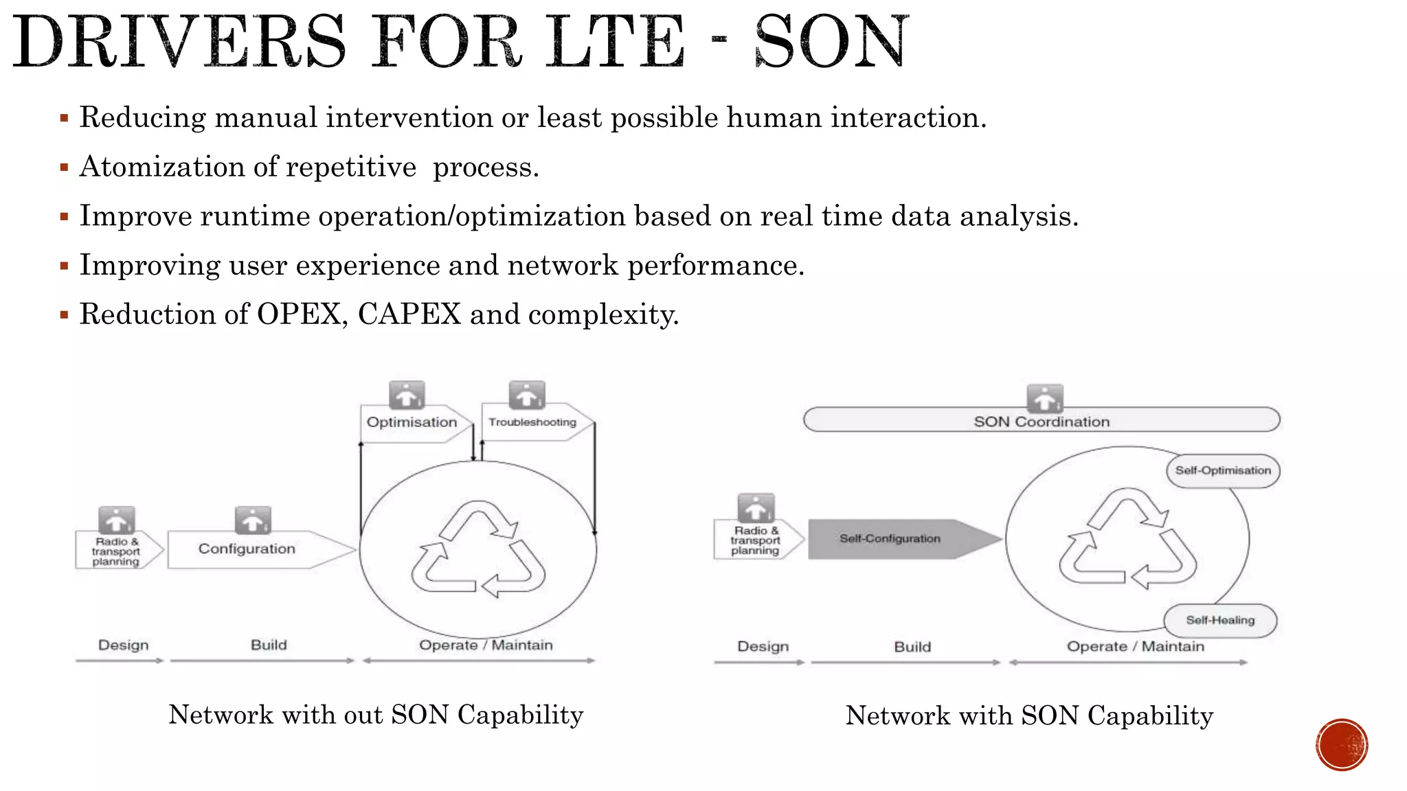


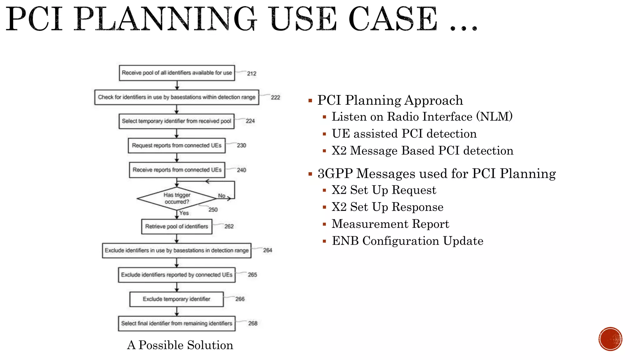


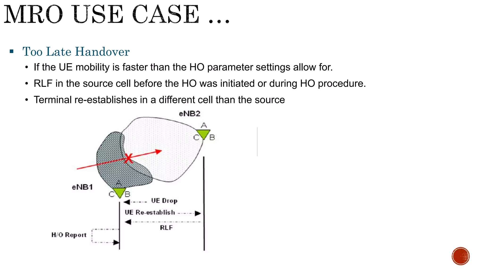
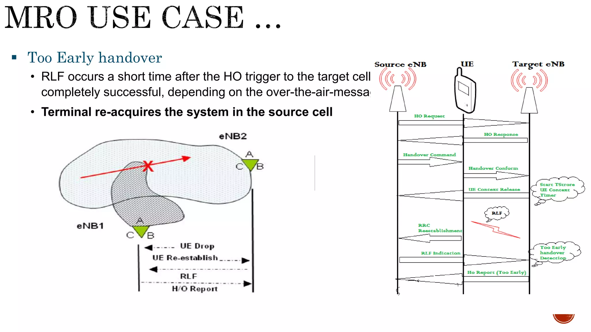

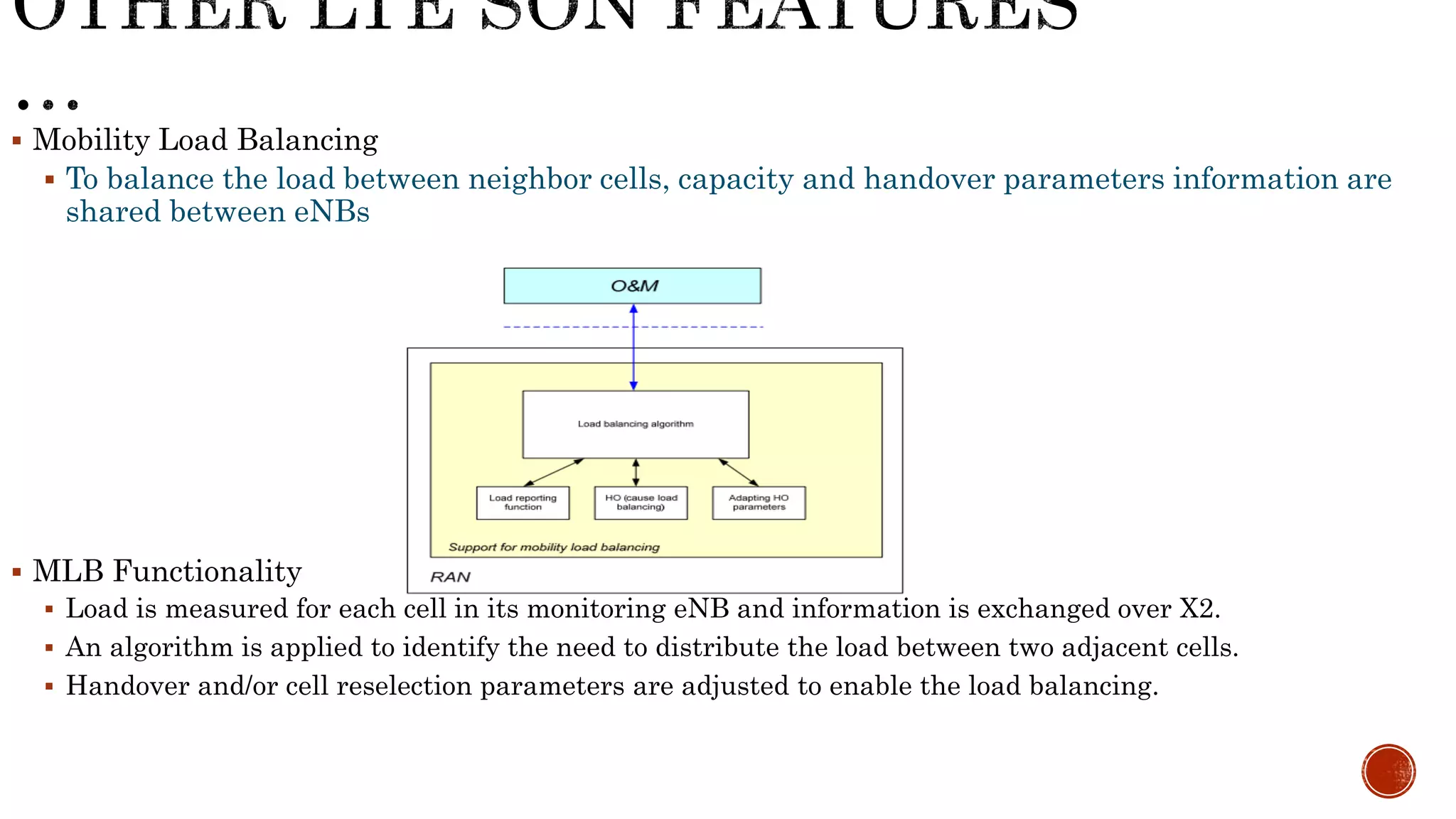

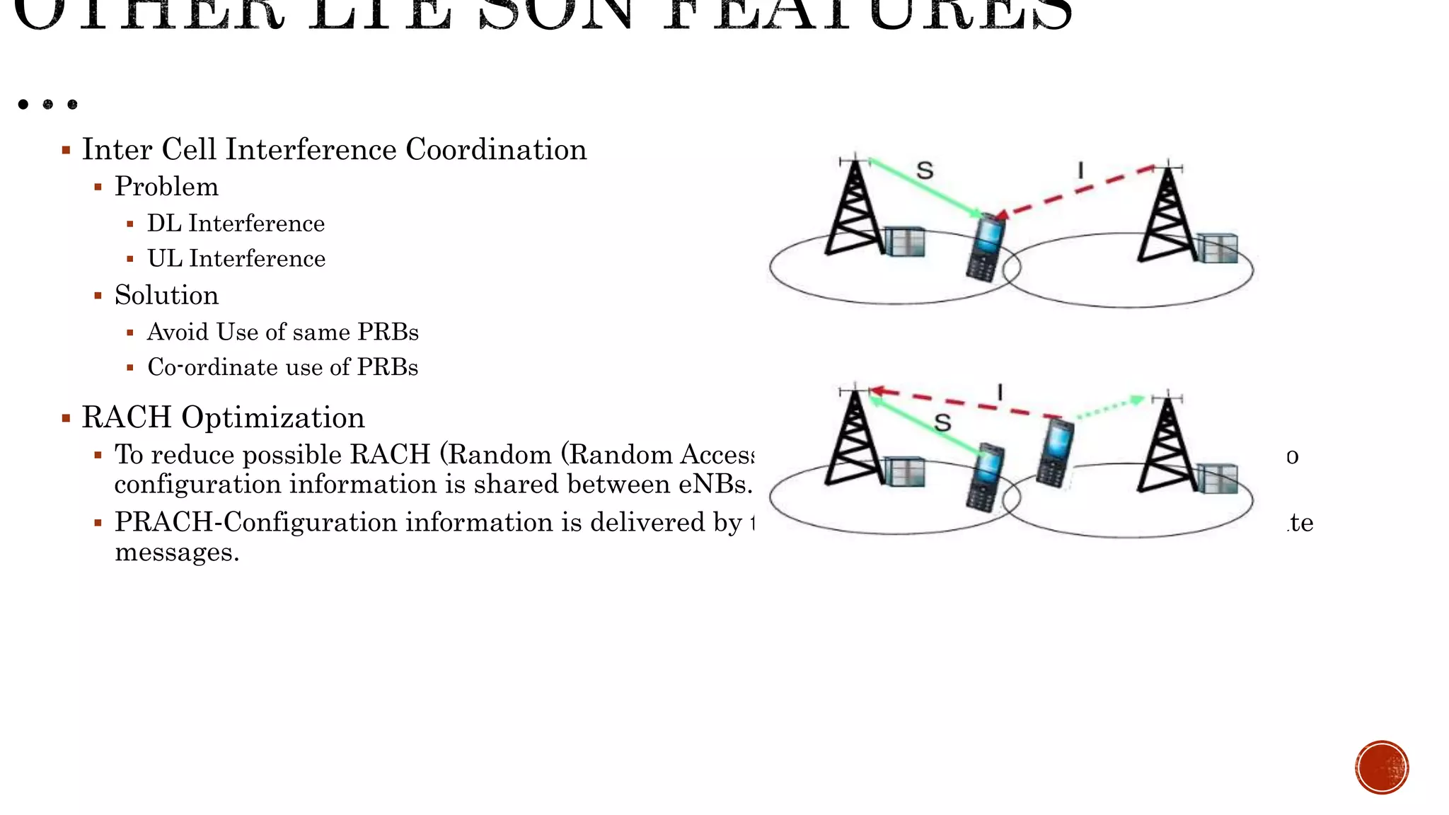
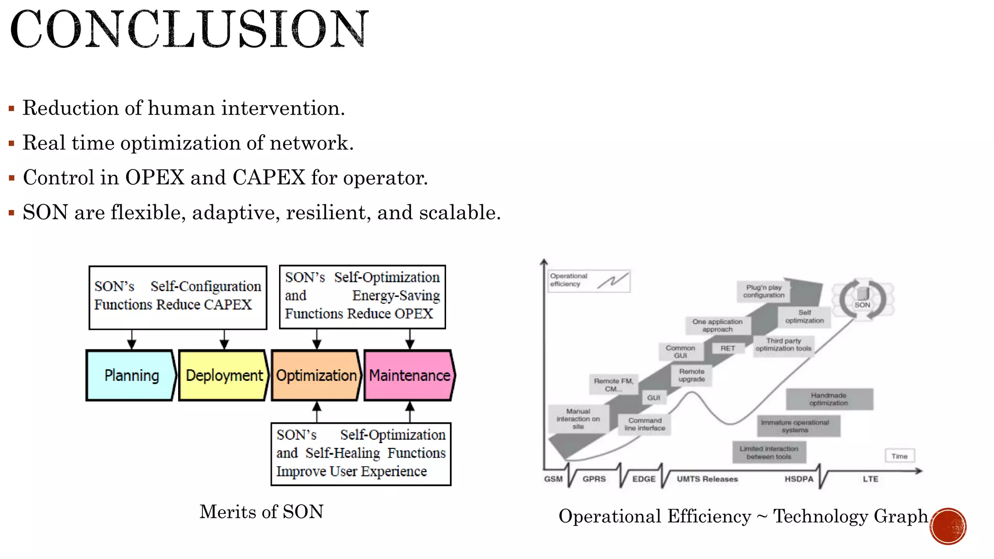


This document discusses Self-Organizing Networks (SON) and its features in LTE networks. It describes the key drivers for SON in LTE including reducing manual intervention, improving performance and user experience. The main SON features covered are self-configuration, self-optimization, and self-healing. Specific use cases explained include PCI planning, ANR, MRO and energy savings. The LTE SON framework and architecture specified by 3GPP is also summarized.


![Coded Agents – with UiPath SDK + LangGraph [Virtual Hands-on Workshop]](https://cdn.slidesharecdn.com/ss_thumbnails/codedagentsdeck-251215155422-5497c599-thumbnail.jpg?width=640&height=640&fit=bounds)