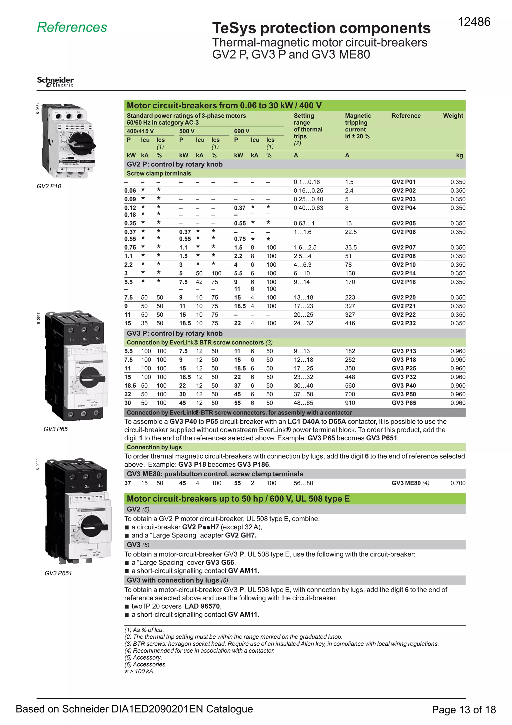
This document provides data on various motor circuit breaker types, including their characteristics, technical specifications, environmental ratings, connection details, and breaking capacities. The GV2 ME and GV2 P circuit breakers can be used with optional current limiter GV1 L3 to increase breaking capacity at higher voltages like 400/415V, 440V, and 500V. Connection options include screw clamp terminals or spring terminals for solid or flexible wires, as well as busbar or lug connections. Environmental ratings include IP20/IP40/IP55 protection, operating temperature range of -20°C to +60°C, and compliance with IEC standards for shock, vibration, and flame resistance testing.
El documento proporciona información sobre el montaje de rodamientos, incluyendo las causas comunes de fallas, los pasos correctos para el montaje, y cómo evitar errores. Algunos puntos clave son controlar la limpieza, el juego radial, el calentamiento adecuado, y evitar golpes o fuerzas durante el montaje.
Diferencias entre PNP y NPN en cableado de autómatas - infoPLC.pdfArnoldquispec
Este documento explica las diferencias entre sensores PNP y NPN utilizados en la automatización industrial. Los sensores PNP tienen una salida positiva mientras que los NPN tienen una salida negativa. El cableado de los sensores depende del tipo, conectando el común del PLC a 24V para NPN o 0V para PNP.
Este documento introduce el control eléctrico de sistemas neumáticos. Explica que un sistema neumático puede ser controlado manualmente o automáticamente, y que el control automático puede realizarse mediante señales eléctricas, aire comprimido o enlaces mecánicos. El objetivo de la primera unidad es familiarizar al estudiante con los componentes del equipo didáctico de neumática y enseñarle a operarlo de forma segura.
Este documento describe los componentes necesarios y el proceso para realizar una partida directa de un motor de jaula de ardilla de tres fases. Los componentes clave incluyen un interruptor magnetotérmico tripolar para proteger el circuito de fuerza, un interruptor magnetotérmico monopolar para proteger el circuito de control, un contactor con contactos auxiliares para abrir y cerrar los circuitos de fuerza y control, y una botonera para encender y apagar el motor. La partida directa es la forma más simple de arrancar un motor al conectar directamente
Este documento describe los diferentes tipos de cilindros y válvulas neumáticas, incluyendo cilindros de simple y doble efecto, y válvulas de 2, 3, 4 y 5 vías. Explica cómo las válvulas de 3 y más vías se pueden usar para controlar cilindros neumáticos y otros elementos, y también describe válvulas de bloqueo y flujo y su simbología.
Este documento presenta aspectos generales sobre el diseño de máquinas, incluyendo definiciones de mecanismos, máquinas, tipos de movimiento, elementos de los mecanismos como eslabones y pares cinemáticos. Explica conceptos como ciclo, período, fase e introduce la cinemática y dinámica en el diseño de máquinas. Además, describe los tipos comunes de pares cinemáticos y la forma en que los mecanismos transmiten movimiento a través de cadenas cinemáticas
Este documento describe tres tipos de válvulas de flujo variable y presenta los resultados de una práctica en la que se midieron las presiones y velocidades de flujo a través de cada válvula. La primera válvula es una válvula de flujo variable simple. La segunda válvula incluye un bypass para permitir el flujo en una dirección independientemente de la apertura de la válvula. La tercera válvula tiene un bypass que mantiene un flujo constante independientemente de la presión. Las mediciones muestran cómo cada
Este documento proporciona información sobre transductores magnéticos y sensores magnéticos. Explica que el magnetismo es un fenómeno físico por el cual los objetos ejercen fuerzas de atracción o repulsión. Los sensores magnéticos detectan variaciones en campos magnéticos en respuesta a cambios físicos y se basan en el efecto Hall. El efecto Hall ocurre cuando una carga eléctrica en movimiento está sujeta a campos eléctricos y magnéticos. Los sensores magnéticos se usan
En esta lista de videos se describen los fundamentos de la oleohidráulica, los componentes más importantes, circuitos hidráulicos simulados en Fluid Sim H
Visita el Canal de Youtube https://youtube.com/playlist?list=PLHTERkK4EZJrRX0CoeyKJ3x9879aBwOga
Visita el Blog https://www.mecatrónica.com.co/p/hidraulica.html
Si te ha sido útil, regálame un Like, comenta y suscríbete :) (◕‿◕)
Visita el Canal de Youtube http://www.youtube.com/c/JovannyDuque?sub_confirmation=1_
Visita el Blog https://www.xn--mecatrnica-lbb.com.co/
Visita el Blog https://mecatronica-itsa.blogspot.com/
Visita el Blog https://www.mecatrónica.com.co/
Este documento trata sobre la clasificación de controladores e identificación de dispositivos de campo utilizados en proyectos de automatización industrial. Incluye una unidad de competencia sobre el análisis de sistemas de automatización industrial y la discriminación de controladores y dispositivos de acuerdo a las características de cada proyecto. También presenta diversos símbolos normalizados para diagramas e instrumentación y control de procesos.
Existen dos tipos principales de circuitos neumáticos: circuitos de anillo cerrado cuyo flujo regresa al origen para evitar fluctuaciones y ofrecer mayor velocidad de recuperación ante fugas, y circuitos de anillo abierto cuya distribución no retorna al origen y requiere que los compresores trabajen más duro. Estos circuitos se pueden dividir en cuatro subsistemas: manuales, semiautomáticos, automáticos y lógicos.
Instrumentación industrial miguel pantojaMiguelps202
El documento describe los conceptos básicos de instrumentación industrial, incluyendo el control manual vs automático, los diferentes tipos de sensores y sus usos para medir variables como presión, temperatura y flujo. También explica los componentes clave de un sistema de control como controladores, elementos finales de control y bucles de realimentación.
Este documento describe las válvulas distribuidoras 3/2 y 4/2. Explica que las válvulas 3/2 permiten el flujo en una dirección y lo bloquean en la otra, mientras que las válvulas 4/2 permiten el flujo en ambas direcciones. Detalla los componentes clave, el funcionamiento y las aplicaciones típicas de cada válvula, así como sus símbolos. Incluye enlaces a videos que muestran estas válvulas en acción.
Este documento presenta información sobre sensores binarios. Brevemente describe que los sensores binarios convierten una magnitud física en una señal lógica o binaria, principalmente una señal eléctrica con los estados de "prendido" y "apagado". Luego menciona algunos tipos de sensores binarios como finales de carrera, sensores de proximidad, presostatos y termostatos.
Este documento describe los componentes principales del banco de pruebas Parker y su simbología. El banco de pruebas incluye un tanque, bomba, válvulas de control, cilindros hidráulicos, manómetros y filtros. También incluye diagramas que muestran la ubicación e interconexión de estos elementos en la unidad de potencia y el depósito de aceite. El objetivo es que los estudiantes identifiquen cada uno de los componentes y comprendan su función en el sistema hidráulico.
U6 Circuitos básicos de alumbrado II.Técnicas de montajeMiguel Á Rodríguez
Este documento presenta el índice de un libro sobre circuitos básicos de alumbrado que incluye lámparas conmutadas. El libro cubre temas como el conmutador, el conmutador de cruce y cinco fichas de trabajo prácticas sobre circuitos de lámparas conmutadas individuales y en cascada. El índice proporciona una descripción general de cada sección e incluye figuras ilustrativas.
Este documento describe las levas, incluyendo su definición, partes, clasificación, funciones y cómo se diseñan. Una leva es un disco con un perfil parcialmente circular que guía el movimiento de un seguidor. Se clasifican según su forma en levas de placa, cilíndricas o laterales. Sirven para transformar movimiento rotatorio en alternativo, como en máquinas y motores. Para diseñar una leva se definen sus movimientos estándar, diagramas de desplazamiento, velocidad y aceleración, y
El documento describe los circuitos eléctrico y neumático de una instalación industrial. El circuito eléctrico incluye la toma de energía trifásica y monofásica, un contactor, interruptor general, relé de control y parada de emergencia. El circuito neumático consta de electroválvulas, válvulas distribuidoras, manómetro, compuerta de seguridad y cinta transportadora. El documento concluye que tanto la energía eléctrica como la neumática son indispensables en la industria moderna
El estrés a que se somete una instalación eléctrica sobrecargada eleva el consumo y aumenta el riesgo de percances que a menudo acaban en un incendio. Es natural que con el paso de los años la instalación eléctrica sufra deterioros o averías. Por ello al revisarla periódicamente es posible garantizar que está en buen estado y prevenir posibles cortos que pueden causar incendios.
Este documento describe las pruebas eléctricas realizadas a interruptores eléctricos de baja, media y alta tensión, incluyendo pruebas de resistencia de contactos, resistencia de aislamiento, tiempo de cierre y apertura, y factor de potencia del aislamiento. También proporciona recomendaciones para realizar estas pruebas de manera segura y efectiva.
Este documento describe los elementos básicos de las máquinas y los automatismos. Explica que una máquina automática contiene estructura, motor, mecanismos, circuitos, actuadores y dispositivos de control, además de automatismos y sistemas de control. Describe los tipos de máquinas, componentes de los circuitos de regulación, diferentes tipos de automatismos como interruptores y relés, y tipos de programadores como los electromecánicos y los que usan chips y microprocesadores.
El documento presenta una introducción a la neumática, incluyendo sus aplicaciones, leyes fundamentales, elementos básicos de una instalación neumática como compresores, refrigeradores, acumuladores, secadores y filtros, y componentes neumáticos comúnmente utilizados junto con su simbología, como válvulas direccionales, reguladores de presión y caudal, cilindros y detectores. También cubre diagramas espacio-fase, ejemplos de circuitos neumáticos y funciones lógicas.
The document discusses different types of circuit breakers, motors, and motor starters including MCBs, MCCBs, isolator switches, single phase motors, three phase motors, induction motors, and direct on line, voltage rated, and solid state starters. It provides details on the applications and characteristics of these circuit protection and motor control components. The classification of induction motors into types A through E is also covered based on their starting current, starting torque, and other performance parameters.
The document discusses different types of circuit breakers, including air blast, vacuum, oil, and SF6 circuit breakers. It explains that a circuit breaker can make, carry, and break currents under normal and abnormal circuit conditions. The operating mechanism involves using stored energy to move a moving contact to open or close the circuit. When contacts separate during a fault, an arc is formed that must be quickly quenched for circuit interruption. Each breaker type uses a different medium, such as air, vacuum, oil or SF6 gas, to rapidly cool and extinguish the arc. Modern systems commonly use vacuum or SF6 breakers for their fast, reliable performance.
This document summarizes the characteristics of 3-pole thermal overload relays, model d:
1) Model d relays are designed to protect AC circuits and motors against overloads, phase failure, long starting times, and prolonged stalling.
2) The relays conform to various industry standards and certifications and have IP2X degree of protection against direct finger contact.
3) Electrical characteristics include operating coils that consume 24-600V at 100-600VA and controlled contactors that operate at 24-440V and 50-100W.
The document provides information on various TeSys circuit breakers, contactors, starters, and accessories for motor protection and control applications. It includes technical specifications such as current and voltage ratings for different models as well as recommended combinations of components for various motor power levels. The table and diagrams allow users to select the appropriate TeSys products based on the requirements of their application and motor.
This presentation will demonstrate how to configure an ABB PLC system, including:
- Configuring I/O modules as per the system configuration
- Configuring the IP address
- Configuring third party Profibus devices like encoders and mass flow meters
- Replacing I/O modules
- Changing node addresses in CI542 DP modules
- Configuring tags in CHMI 5.1 SCADA
- Configuring trends and alarms
Catalog: mccb elcb mitsubishi electric
Beeteco.com là trang mua sắm trực tuyến thiết bị điện - Tự động hóa uy tín tại Việt Nam.
Chuyên cung cấp các thiết bị: Đèn báo nút nhấn, Relay, Timer, Contactor, MCCB ELCB, Biến tần, Van, Thiết bị cảm biến, phụ kiện tủ điện, .... Từ các thương hiệu hàng đầu trên thế giới.
www.beeteco.com @ Công ty TNHH TM KT ASTER
Số 7 Đại Lộ Độc Lập, KCN Sóng Thần 1, P. Dĩ An, Tx. Dĩ An, Bình Dương
www.facebook.com/beeteco
Tel: 0650 3617 012
DĐ: 0904 676 925
Scada Based Online Circuit Breaker Monitoring SystemIOSR Journals
This document discusses the design and implementation of an online monitoring system for circuit breakers using SCADA technology. The system would monitor key parameters of circuit breakers like currents, voltages, pressures and temperatures. Sensors would collect data which would be sent to a data acquisition unit and then to a central computer via a communication network. The computer would store data histories and use SCADA software to allow remote monitoring. The system architecture includes sensors, intelligent electronic devices for data collection, and a central computer running analysis software to evaluate breaker condition and guide maintenance. The online monitoring allows reliable supervision of circuit breakers to improve power system reliability.
Password based circuit breaker using dc motorSAURABH AGRAWAL
This power point presentation describes a password based circuit breaker that uses a microcontroller, LCD display, keypad, DC motor, and motor driver IC. The circuit breaker will automatically open when a fault is detected in the line. If no fault is present, the user must first enter the correct password before the circuit breaker will open. The circuit uses the microcontroller to read inputs from the keypad and control the LCD and motor driver IC to operate the DC motor that opens and closes the circuit breaker. The password protected system provides an important safety and security feature to prevent unauthorized access to electrical systems.
Catalog MCCB ELCB Shillin Electric
Beeteco.com là trang mua sắm trực tuyến thiết bị điện - Tự động hóa uy tín tại Việt Nam.
Chuyên cung cấp các thiết bị: Đèn báo nút nhấn, Relay, Timer, Contactor, MCCB ELCB, Biến tần, Van, Thiết bị cảm biến, phụ kiện tủ điện, .... Từ các thương hiệu hàng đầu trên thế giới.
www.beeteco.com @ Công ty TNHH TM KT ASTER
Địa chỉ : Số 7/31 KDC Thương Mại Sóng Thần, KP. Nhị Đồng 1, P. Dĩ An, Tx. Dĩ An, Tỉnh Bình Dương
FB: www.facebook.com/beeteco
Email: contact@beeteco.com
Tel: 0650 3617 012
Hotline: 0909.41.61.43
The document describes a centrifugal oil cleaner system that can be installed on various wire and tube drawing machines and applications. It removes metallic sludge from drawing oils, increasing die life, improving product quality, and reducing costs. Key benefits include no replacement elements needed, increased oil life, reduced oil consumption and machine downtime, and substantial savings on oil replacement costs. It works by using centrifugal force to separate sludge from oil inside a high-speed rotor, with clean oil returning to the tank by gravity.
This document summarizes a seminar presentation about circuit breakers. It defines a circuit breaker as equipment that can break an electric circuit manually or automatically under various load conditions. It then describes the operating principle of circuit breakers and the arc phenomenon that occurs when contacts are separated. Various types of circuit breakers are discussed, including oil, air blast, SF6, and vacuum circuit breakers. The document focuses on the advantages of SF6 circuit breakers for high voltage applications, as SF6 gas is effective at extinguishing arcs due to its ability to capture electrons from arcs.
Genca is a global leader in rubber and plastic molding processes. They produce tube clamps and use extrusion tools and die design to increase efficiency and output. Genca provides services such as tube clamp manufacturing, extrusion tool utilization, and extrusion die design from their location in Saint Petersberg, Florida.
This document provides information about NIEHOFF OF INDIA Pvt. Ltd., a company that manufactures wire drawing machines. It discusses the company's background, facilities, products, manufacturing processes, and key machines used. The company's products include tandem rod breakdown machines, wire annealers, dancer machines, spoolers, and bunchers. The manufacturing process involves steps like sales order processing, engineering, production planning, purchasing, inspection, assembly, and testing. Machines like lathes, grinders, and pneumatic tools are used in assembly.
Password based circuit breaker control to ensure electricPraveen Kumar V
This document describes a password-based circuit breaker control system to ensure the safety of electric line workers. The system uses a PIC16F877A microcontroller and requires a line worker to enter a password to turn the circuit breaker on or off. This allows the line worker to safely repair power lines by turning off the supply, completing repairs, and then returning to the substation to turn the power back on by entering the correct password. The system indicators and password entry is controlled by the microcontroller.
The document discusses different types of metal coated steel products, including galvanized steel, galvalume, galvannealed, and galfan. It explains that the coatings protect the steel surface from corrosion and oxidation. Each product has different applications depending on its environment. The document provides details on the composition, coating designations, applications, and corrosion resistance of the four main coated steel products. It also discusses trademarks, grade designations, and additional information about standards and pre-painted varieties.
The document summarizes the wire drawing process. Wire drawing is used to reduce the cross-sectional area of wire by pulling it through progressively smaller dies. There are single step and continuous wire drawing machines. Proper lubrication is important for smooth finishes and long die life. Different types of dies and materials are used depending on the type of wire. Automation using programmable logic controllers allows maintaining constant speed and drawing force for high accuracy and reduced labor costs.
MCB stands for Miniature Circuit Breaker. It is a manually or automatically operated electrical switch designed to protect an electrical circuit from damage caused by overload or short circuit. It detects fault conditions and interrupts current flow, unlike a fuse which must be replaced after operating. MCBs protect individual appliances up to large high voltage circuits for cities. They automatically switch off circuits during abnormal network conditions like overloads or faults. MCBs are more sensitive to overcurrent than fuses but can be reset to resume operation, while an advantage of fuses is they are less costly than MCB systems.
Miniature Circuit Breakers (MCBs) provide overcurrent protection in electrical circuits. MCBs have replaced traditional fuses in many applications. MCBs have three main components: a thermal unit to sense overloads, a magnetic unit to sense short circuits, and arc chutes to suppress arcs. When too much current flows, the bimetal in the thermal unit bends and trips the circuit. For short circuits, a magnetic field trips the circuit. MCBs can be reset by flipping the switch after a fault is corrected, while fuses must be replaced. MCBs are more compact, reusable, and provide easier fault identification than fuses.
Series of powerpoint slides showing three different drawing processes used in the manufacture of wires, rod, tubes and drinks cans. The slides are adapted from the University of Liverpool "Materials Processing" lectures [MATS214] by Dr J. Wilcox.
SIBA URDC DC fuses are available for use on traction, battery and railway circuit applications - traction fuses are designed for heavy duty circuit protection to following standards UIC550, IEC60269 and VDE 0636-40.
The document provides information on TeSys rotary handles, circuit breakers, contactors, starters, and overload relays for motor protection and control applications. It includes technical specifications such as current and power ratings for various models of these components suitable for applications from fractional to several hundred horsepower. The table and descriptions allow users to select the appropriate component models based on the requirements of their motor control application.
iemens 3VJ molded case circuit breaker (MCCB) brochure provides information on the 3VJ series, which is designed for low-voltage power distribution and protection in industrial and commercial applications. The brochure may contain technical specifications, features, and benefits of the 3VJ series, such as:
Rated current from 100A to 630A
Breaking capacity up to 65kA at 415V AC
Adjustable overload protection and short-circuit protection
Compatibility with various accessories, including auxiliary switches, shunt trips, and undervoltage releases
This document provides information on DC switch-disconnectors for photovoltaic installations, including their main features, ratings, and applications. The switches are designed according to UL98B, UL508i, and IEC/EN 60947 standards and are available in ratings from 16 to 630 amps and 1000-1500 volts. They provide load break switching capability and various mounting and interlocking options for use in solar inverters, combiner boxes, and battery chargers to safely isolate circuits during maintenance.
Cataloge ge 2.industrial components_dienhathe.com-1_record_plusDien Ha The
The document discusses GE's Record Plus line of molded case circuit breakers. It provides an overview of the breakers, including their technical specifications and performance figures. It also lists relevant safety standards and certifications. The summary highlights the breakers' selective and current limiting protection capabilities, interchangeable trip units for flexible protection, common accessories, and versatile installation options.
Cataloge ge 2.industrial components-1_record_plusThuan Kieu
Cataloge ge 2.industrial components-1_record_plus
Catalog GE,
Catalog Thiết Bị Điện GE,
Catalog Điện Công Nghiệp GE,
http://dienhathe.com,
Xem thêm các sản phẩm khác của GE tại https://dienhathe.com
Để nhận báo giá sản phẩm GE vui lòng gọi: 0907.764.966
Cataloge ge 2.industrial components-1_record_plusDien Ha The
Cataloge ge 2.industrial components-1_record_plus
Catalog GE, Catalog,
Catalog Thiết Bị Điện GE, Catalog Thiết Bị Điện,
Catalog Điện Công Nghiệp GE, Catalog Điện Công Nghiệp,
http://dienhathe.com,
Xem thêm các sản phẩm khác của GE tại https://dienhathe.com
Để nhận báo giá sản phẩm GE vui lòng gọi: 0907.764.966
This document describes Switch Mode Power Supply models ranging from 15W to 350W. It provides specifications for each model including input/output ratings, efficiency, protection features, construction details, and standards compliance. The power supplies offer high reliability and stable operation for equipment applications with output voltages of 5V, 12V, 15V, 24V, 36V or 48V.
This document provides product details for a miniature circuit breaker (MCB) called the S201-K25NA. It is a 1+NP pole, K characteristic, 25A rated current MCB that meets IEC and UL standards. It has thermal and magnetic tripping mechanisms for overload and short circuit protection. Additional information is given on technical specifications, ratings, dimensions, packaging, ordering, and accessories.
Catalogue thiet bi dien abb rccb rcbo abb-dienhathe.vnDien Ha The
This document provides information on various electrical distribution and control devices from ABB, including:
- DS271 series single pole RCBOs rated from 6A to 32A for protection in electrical distribution systems.
- E250 series latching relays rated up to 16A with various contact configurations for remote control applications.
- E220 series pushbuttons and indicator lamps rated up to 16A for use in electrical installations for remote control and signaling.
Catalog rccb va rcbo abb
Catalog ABB,
Catalog Thiết Bị Điện ABB,
Catalog Điện Công Nghiệp ABB,
http://dienhathe.com,
Xem thêm các sản phẩm khác của ABB tại https://dienhathe.com
Để nhận báo giá sản phẩm ABB vui lòng gọi: 0907.764.966
EasyPactEZC circuit breakers from Schneider Electric provide low voltage protection from 15A to 630A. They come in just three frame sizes and include fixed and plug-in versions. They comply with worldwide standards and have international certifications. The catalog introduces the EasyPactEZC range and provides information on functions, characteristics, accessories, installation guidelines, and part numbers.
Kyoritsu 3125A High Voltage Insulation Tester 5kV
High Voltage Insulation Tester 5kV
Model: 3125A
Kyoritsu - Japan
• Insulation Resistance up to 1TO
• Short-Circuit Current up to 1.5mA
• Wide Test Voltage from 250V to 5000V
• Diagnosis Function of PI and DAR
• Newly-designed alligator clip
• It comes with a tough hard case
• Filter function reduces noise interference for obtaining stable measurement
• Large display with Bar Graph indication and backlight
• Live voltage warning
• Safety standard IEC 61010-1 CAT IV 300V / CAT III 600V
ROnex International
47/2, Fazli Rabbi Road, Motijheel, Dhaka-1000.
+880-1811-155717, 01612-526665
ronexbd@gmail.com
https://ronexbd.wixsite.com/ronexbd/
Kyoritsu 3125A Digital High Voltage Insulation Tester 5kVROnex International
Digital High Voltage Insulation Tester 5kV
Model: 3125A
Kyoritsu - Japan
Product Review
• Insulation Resistance up to 1TΩ
• Short-Circuit Current up to 1.5mA
• Wide Test Voltage from 250V to 5000V (250/500/1000/2500/5000V)
• Diagnosis function of polarization index (PI) and dielectric absorption ratio (DAR)
• Newly-designed alligator clip
• Supplied in hard carry case
For more information, please contact us
ROnex International | 47/2, Fazli Rabbi Road, Motijheel, Dhaka-1000. Bangladesh | Cell: +880 1811155717 | E-mail: ronexbd@gmail.com | Webs: https://ronexbd.wixsite.com/ronexbd | Skype: ronexbd | https://facebook.com/RonexInternational
This document provides an index and technical specifications for low voltage switchgear products, including:
- Mini contactors ranging from 0.16-0.22kg for switching electric motors and other loads up to 7.5kW at 230V and 22kW at 690V.
- Contactors relays from 0.16-0.22kg for switching loads up to 2A at 500V and 1A at 690V.
- Motor protection switches from 20-32A for motor circuit protection.
- Miniature circuit breakers from 20-120A for overload and short circuit protection.
- Accessories like auxiliary switch blocks, connection cabinets, and multi-functional
This document provides information on miniature circuit breakers and residual current devices, including:
- Miniature circuit breakers of types BKP, BKN, and BKH with ratings from 1A to 125A and characteristics curves of B, C, and D.
- Residual current circuit breakers with overcurrent protection of types RKP, RKS, RKS-b, 32KGR, and 32GRh with ratings from 3A to 50A.
- Residual current circuit breakers of types RKN and RKN-b with ratings from 25A to 100A.
- Isolators of type BKD with ratings from 40A to 125A.
It provides specifications
1) The document provides specifications for TeSys contactors and reversing contactors for various applications and power ratings.
2) It includes information on rated operational current and voltage, number of poles, rated operational power, auxiliary contacts, thermal overload relays, suppressor modules, interfaces and contactor/reversing contactor type references.
3) The contactors and reversing contactors can be used for applications such as industrial control systems, building automation systems, and other control system applications. They provide operational power ratings from 1.5kW to 900kW at voltages ranging from 220V to 690V.
Catalog thiết bị đóng cắt Fuji Electric - Molded Case Circuit Breakers BX Series
*********************************************************************
CTY TNHH HẠO PHƯƠNG - Nhà phân phối chính thức các thiết bị điện công nghiệp và tự động hóa của hãng FUJI ELECTRIC JAPAN tại Việt Nam
Xem chi tiết các sản phẩm Fuji Electric tại
http://haophuong.com/b1033533/fuji-electric
Đang phục vụ cho hơn 30% nhu cầu của Việt nam với mức chất lượng cao nhất của thế giới ( high-end và Standard range). Sản phẩm này cũng đang được bán tại Mỹ, Nhật, Eu, và Trung đông,… Tại Việt nam, từ năm 1998 đến nay, LS đã và đang cung cấp cho hàng ngàn công trình lớn nhỏ tại Việt nam bao gồm các nhà đầu tư Nhật bản, Hàn Quốc, và các nhà đầu tư Việt nam.
Similar to schneider gv2 motor circuit breaker (20)
3 Simple Steps To Buy Verified Payoneer Account In 2024SEOSMMEARTH
Buy Verified Payoneer Account: Quick and Secure Way to Receive Payments
Buy Verified Payoneer Account With 100% secure documents, [ USA, UK, CA ]. Are you looking for a reliable and safe way to receive payments online? Then you need buy verified Payoneer account ! Payoneer is a global payment platform that allows businesses and individuals to send and receive money in over 200 countries.
If You Want To More Information just Contact Now:
Skype: SEOSMMEARTH
Telegram: @seosmmearth
Gmail: seosmmearth@gmail.com
Zodiac Signs and Food Preferences_ What Your Sign Says About Your Tastemy Pandit
Know what your zodiac sign says about your taste in food! Explore how the 12 zodiac signs influence your culinary preferences with insights from MyPandit. Dive into astrology and flavors!
LA HUG - Video Testimonials with Chynna Morgan - June 2024Lital Barkan
Have you ever heard that user-generated content or video testimonials can take your brand to the next level? We will explore how you can effectively use video testimonials to leverage and boost your sales, content strategy, and increase your CRM data.🤯
We will dig deeper into:
1. How to capture video testimonials that convert from your audience 🎥
2. How to leverage your testimonials to boost your sales 💲
3. How you can capture more CRM data to understand your audience better through video testimonials. 📊
Company Valuation webinar series - Tuesday, 4 June 2024FelixPerez547899
This session provided an update as to the latest valuation data in the UK and then delved into a discussion on the upcoming election and the impacts on valuation. We finished, as always with a Q&A
Discover timeless style with the 2022 Vintage Roman Numerals Men's Ring. Crafted from premium stainless steel, this 6mm wide ring embodies elegance and durability. Perfect as a gift, it seamlessly blends classic Roman numeral detailing with modern sophistication, making it an ideal accessory for any occasion.
https://rb.gy/usj1a2
Storytelling is an incredibly valuable tool to share data and information. To get the most impact from stories there are a number of key ingredients. These are based on science and human nature. Using these elements in a story you can deliver information impactfully, ensure action and drive change.
Best practices for project execution and deliveryCLIVE MINCHIN
A select set of project management best practices to keep your project on-track, on-cost and aligned to scope. Many firms have don't have the necessary skills, diligence, methods and oversight of their projects; this leads to slippage, higher costs and longer timeframes. Often firms have a history of projects that simply failed to move the needle. These best practices will help your firm avoid these pitfalls but they require fortitude to apply.
Implicitly or explicitly all competing businesses employ a strategy to select a mix
of marketing resources. Formulating such competitive strategies fundamentally
involves recognizing relationships between elements of the marketing mix (e.g.,
price and product quality), as well as assessing competitive and market conditions
(i.e., industry structure in the language of economics).
Understanding User Needs and Satisfying ThemAggregage
https://www.productmanagementtoday.com/frs/26903918/understanding-user-needs-and-satisfying-them
We know we want to create products which our customers find to be valuable. Whether we label it as customer-centric or product-led depends on how long we've been doing product management. There are three challenges we face when doing this. The obvious challenge is figuring out what our users need; the non-obvious challenges are in creating a shared understanding of those needs and in sensing if what we're doing is meeting those needs.
In this webinar, we won't focus on the research methods for discovering user-needs. We will focus on synthesis of the needs we discover, communication and alignment tools, and how we operationalize addressing those needs.
Industry expert Scott Sehlhorst will:
• Introduce a taxonomy for user goals with real world examples
• Present the Onion Diagram, a tool for contextualizing task-level goals
• Illustrate how customer journey maps capture activity-level and task-level goals
• Demonstrate the best approach to selection and prioritization of user-goals to address
• Highlight the crucial benchmarks, observable changes, in ensuring fulfillment of customer needs
Recruiting in the Digital Age: A Social Media MasterclassLuanWise
In this masterclass, presented at the Global HR Summit on 5th June 2024, Luan Wise explored the essential features of social media platforms that support talent acquisition, including LinkedIn, Facebook, Instagram, X (formerly Twitter) and TikTok.
Top mailing list providers in the USA.pptxJeremyPeirce1
Discover the top mailing list providers in the USA, offering targeted lists, segmentation, and analytics to optimize your marketing campaigns and drive engagement.
Hamster Kombat' Telegram Game Surpasses 100 Million Players—Token Release Sch...
schneider gv2 motor circuit breaker
1. Issued November 2009 12486
DATA SHEET
GV2ME & GV2P
MOTOR
CIRCUIT BREAKER
Based on Schneider DIA1ED2090201EN Catalogue
2. Characteristics
Environment
Circuit-breaker type GV2 ME GV2 P GV3 P GV3 ME80 GV7 R
Conforming to standards IEC 60947-1, 60947-2,
60947-4-1,
EN 60204, UL 508,
CSA C 22.2 n° 14-05,
NF C 63-650, 63-120, 79-130,
VDE 0113, 0660
IEC/EN
60947-1,
60947-2,
60947-4-1,
UL 508 type E,
CSA C 22.2
n° 14-05 type E
IEC/EN, NF
EN, BS EN,
DINEN60947-2,
60947-4-1
IEC 60947-1,
60947-2,
60947-4-1,
EN 60947-1,
60947-2,
EN 60947-4-1,
NF C 63-650,
NF C 63-120,
79-130,
VDE 0113,
0660
Product certifications UL, CSA, CCC,
CEBEC,
GOST, TSE,
BV, GL, LROS ,
DNV, PTB,
EZU, SETI,
RINA, ATEX
UL (1), CSA,
PTB, EZU,
GOST, TSE,
DNV, LROS,
GL, BV, RINA,
CCC, ATEX
UL, CSA,
CCC (pending),
GOST,
ATEX (pending)
UL, CSA,
LROS
UL, DNV,
CCC
Protective treatment “TH” “TH” “TC” “TC”
Degree of protection Conforming to
IEC 60529
Open mounted IP 20 IP 20 IP 20 IP 405 with
terminal
shrouds
In enclosure GV2 Mp01:
IP 41
GV2 Mp02:
IP 55
– GV3 PC01 and
GV3 PC02: IP 55
GV3 CE01:
IP 55
–
Shock resistance Conforming to IEC 60068-2-27 30 gn -11 ms On: 15 gn -11 ms
Off:30 gn -11 ms
22 gn - 20 ms 15 gn -11 ms
Vibration resistance Conforming to IEC 60068-2-6 5 gn (5…150 Hz) 4 gn
(5…300 Hz)
2.5 gn
(0…25 Hz)
2.5 gn (25 Hz)
Ambient air temperature Storage °C - 40…+ 80 - 40…+ 80 - 40…+ 80 - 40…+ 80 - 55…+ 95
Operation Open mounted °C - 20…+ 60 - 20…+ 60 - 20…+ 60 (2) - 20…+ 60 - 25… + 70
In enclosure °C - 20…+ 40 - 20…+ 40 - 20…+ 40 - 20…+ 40 –
Temperature compensation Open mounted °C - 20…+ 60 - 20…+ 60 - 20…+ 60 - 20…+ 60 - 25… + 55 (3)
In enclosure °C - 20…+ 40 - 20…+ 40 - 20…+ 40 - 20…+ 40 –
Flame resistance Conforming to IEC 60695-2-1 °C 960 960 960 960
Maximum operating altitude m 2000 3000 3000 2000
Suitable for isolation Conforming to IEC 60947-1 § 7-1-6 Yes Yes – Yes
Resistance to mechanical impact J 0.5 0.5 10 0.5 0.5
IK 04 IK 09
(in enclosure)
– –
Sensitivity to phase failure Yes, conforming to IEC 60947-4-1 § 7-2-1-5-2
Technical characteristics
Circuit-breaker type GV2 ME GV2 P GV2 RT GV3 P GV3
ME80
GV7
Rp20...
Rp100
GV7
Rp150
GV7
Rp220
Utilisation category Conforming to IEC 60947-2 A A A A
Conforming to IEC 60947-4-1 AC-3 AC-3 AC-3 AC-3
Rated operational voltage
(Ue)
Conforming to IEC 60947-2 V 690 690 690 690
Rated insulation voltage
(Ui)
Conforming to IEC 60947-2 V 690 690 690 750
Rated voltage Conforming to CSA C22-2 n° 14,
UL 508
V 600 600 600
(B600)
600
Rated operational
frequency
Conforming to IEC 60947-4-1
UL, CSA
Hz 50/60 50/60 50/60 50/60
Rated impulse withstand
voltage (U imp)
Conforming to IEC 60947-2 kV 6 6 6 8
Total power dissipated per pole W 2.5 8 8 5 8.7 14.5
Mechanical durability
(C.O.: Close, Open)
C.O. 100 000 50 000 30 000 50 000 40 000 20 000
Electrical durability
for AC-3 duty
440 V In/2 C.O. 100 000 – 30 000 50 000 40 000 20 000
440 V In C.O. – 50 000 – 30 000 20 000 10 000
Duty class (maximum operating rate) C.O./h 25 25 25 25
Maximum conventional
rated thermal current (Ith)
Conforming to IEC 60947-4-1 A 0.16…
32
0.16…
32
0.40…
23
13…
65
80 12…
100
150 220
Rated duty Conforming to IEC 60947-4-1 Continuous duty
(1) UL 508 type E for GV2 PppH7
(2) Leave a space of 9 mm between 2 circuit-breakers: either an empty space, or side mounting add-
on contact blocks. Side by side mounting is possible up to 40 °C.
(3) For operation up to 70 °C, please consult your Regional Sales Office.
TeSys protection components
Thermal-magnetic motor circuit-breakers
1
2
3
4
5
6
7
8
9
10
12486
Based on Schneider DIA1ED2090201EN Catalogue Page 1 of 18
3. Characteristics (continued)
Mounting characteristics
Operating position
Without derating, in relation to normal vertical mounting plane (1)
Connection characteristics
Connection to screw clamp terminals or spring terminals
Bare cables
Circuit-breaker type GV2 ME GV2 P GV3 P GV3 ME80
Connection to screw clamp terminals
(2)
(Max. number of
conductors x c.s.a.)
Min. Max. Min. Max. Min. Max. Min. Max.
Solid cable mm2
2 x 1 2 x 6 2 x 1 2 x 6 2 x 1 1 x 25 and
1 x 35
1 x 2.5 1 x 35
Flexible cable
without cable end
mm2
2 x 1.5 2 x 6 2 x 1.5 2 x 6 2 x 1 1 x 25 and
1 x 35
1 x 2.5 2 x 16
Flexible cable
with cable end
mm2
2 x 1 2 x 4 2 x 1 2 x 4 2 x 1 1 x 25 and
1 x 35
1 x 2.5 2 x 16
Tightening torque N.m 1.7 1.7 1.7 1.7 5 5: 25 mm2
8: 35 mm2
5 5
Connection to spring terminals
Number of conductors x c.s.a.
Solid cable mm2
2 x 1 (3) 2 x 6 – – – – – –
Flexible cable
without cable end
mm2
2 x 1.5 (3) 2 x 4 – – – – – –
Connection by bars or lugs
Bars or lugs
Circuit-breaker type GV2 MEpp6 GV3 Ppp6 GV7
Rp20...Rp100
GV7 Rp150 GV7 Rp220
Pitch Without spreaders mm 13.5 17.5 35 35 35
With spreaders mm – – 45 45 45
Bars or cables with lugs e mm y 6 y 6 y 6 y 6 y 6
L mm y 9.5 y 13.5 y 25 y 25 y 25
L’ mm y 9.5 y 16.5 – – –
d mm y 10 y 10 y 10 y 10 y 10
Screws M4 M6 M6 M8 M8
Tightening torque N.m 1.7 6 10 15 15
Bare cables (copper or aluminium)
with connectors
Height (h) mm – – 20 20 20
C.s.a. mm2
– – 1.5...95 1.5...95 1.5...185
Tightening torque N.m – – 15 15 15
(1) When mounting on a vertical rail, fit a stop to prevent any slippage.
(2) For motor circuit-breakers GV3 P: BTR hexagon socket head screws, EverLink®
system.
Require use of an insulated Allen key, in compliance with local electrical wiring regulations.
(3) For cross-sections 1 to 1.5 mm2
, the use of an LA9 D99 cable end reducer is recommended.
90˚
90˚
90˚
90˚
90˚
90˚
90˚
90˚
hh
e
d
L
d
L L'
Ø6
e
d
L
d
L L'
Ø6
TeSys protection components
Thermal-magnetic motor circuit-breakers
1
2
3
4
5
6
7
8
9
10
12486
Based on Schneider DIA1ED2090201EN Catalogue Page 2 of 18
4. Characteristics
Breaking capacity of GV2 ME and GV2 P
Circuit-breaker type GV2 ME GV2 P
01
to
06
07 08 10 14 16 20 21
&
22
32 01
to
06
07 08 10 14 16 20 21
&
22
32
Rating A 0.1
to
1.6
2.5 4 6.3 10 14 18 23
&
25
32 0.1
to
1.6
2.5 4 6.3 10 14 18 23
&
25
32
Breaking capacity
conforming to IEC 60947-2
230/240 V Icu kA g g g g g g g 50 50 g g g g g g g g g
Ics % (1) g g g g g g g 100 100 g g g g g g g g g
400/415 V Icu kA g g g g g 15 15 15 10 g g g g g g 50 50 50
Ics % (1) g g g g g 50 50 40 50 g g g g g g 50 50 50
440 V Icu kA g g g 50 15 8 8 6 6 g g g g g 50 20 20 20
Ics % (1) g g g 100 100 50 50 50 50 g g g g g 75 75 75 75
500 V Icu kA g g g 50 10 6 6 4 4 g g g g 50 42 10 10 10
Ics % (1) g g g 100 100 75 75 75 75 g g g g 100 75 75 75 75
690 V Icu kA g 3 3 3 3 3 3 3 3 g 8 8 6 6 6 4 4 4
Ics % (1) g 75 75 75 75 75 75 75 75 g 100 100 100 100 100 100 100 100
Associated fuses (if required)
if Isc > breaking capacity Icu
conforming to IEC 60947-2
230/240 V aM A g g g g g g g 80 80 g g g g g g g g g
gG A g g g g g g g 100 100 g g g g g g g g g
400/415 V aM A g g g g g 63 63 80 80 g g g g g g 100 100 100
gG A g g g g g 80 80 100 100 g g g g g g 125 125 125
440 V aM A g g g 50 50 50 50 63 63 g g g g g 50 63 80 80
gG A g g g 63 63 63 63 80 80 g g g g g 63 80 100 100
500 V aM A g g g 50 50 50 50 50 50 g g g g 50 50 50 50 50
gG A g g g 63 63 63 63 63 63 g g g g 63 63 63 63 63
690 V aM A g 16 25 32 32 40 40 40 40 g 20 25 40 40 50 50 50 50
gG A g 20 32 40 40 50 50 50 50 g 25 32 50 50 63 63 63 63
g > 100 kA.
(1) As % of Icu.
TeSys protection components
Thermal-magnetic motor circuit-breakers
GV2 ME and GV2 P
1
2
3
4
5
6
7
8
9
10
12486
Based on Schneider DIA1ED2090201EN Catalogue Page 3 of 18
5. Characteristics (continued)
Breaking capacity of GV2 ME and GV2 P (used in association with current limiter GV1 L3)
Circuit-breaker type GV2 ME
01 to 06 07 08 10 14 16 20 21 22 32
Rating A 0.1 to
1.6
2.5 4 6.3 10 14 18 23 25 32
Breaking capacity
conforming to IEC 60947-2
230/240 V Icu kA g g g g g g g g g g
Ics % (1) g g g g g g g g g g
400/415 V Icu kA g g g g g 100 100 100 100 100
Ics % (1) g g g g g 50 50 40 40 40
440 V Icu kA g g g g g 50 20 20 20 20
Ics % (1) g g g g g 75 75 75 75 75
500 V Icu kA g g g g 50 42 10 10 10 10
Ics % (1) g g g g 100 100 75 75 75 75
Circuit-breaker type GV2 P
01 to 06 07 08 10 14 16 20 21 22 32
Rating A 0.1 to
1.6
2.5 4 6.3 10 14 18 23 25 32
Breaking capacity
conforming to IEC 60947-2
230/240 V Icu kA g g g g g g g g g g
Ics % (1) g g g g g g g g g g
400/415 V Icu kA g g g g g g g g g g
Ics % (1) g g g g g g g g g g
440 V Icu kA g g g g g 100 100 100 100 100
Ics % (1) g g g g g 50 50 50 50 50
500 V Icu kA g g g g 100 100 100 100 100 100
Ics % (1) g g g g 50 50 50 50 50 50
690 V (3) Icu = Ics kA g 50 50 50 50 50 50 50 50 50
Circuit-breaker type GV2 ME
01 to 06 07 08 10 14 16 20 21 22 32
Rating A 0.1
to 1.6
2.5 4 6.3 10 14 18 23 25 32
Cable protection against
thermal stress in the
event of short-circuit
(PVC insulated copper cables)
Minimum
c.s.a.
protected
at 40 °C
at Isc max.
1 mm2 p p p y 10 kA y 6 kA (2) (2) (2) (2) (2)
1.5 mm2
p p p y 20 kA y 10 kA (2) (2) (2) (2) (2)
2.5 mm2
p p p p p p p p p (2)
4…6 mm2
p p p p p p p p p p
g > 100 kA
p Cable c.s.a. protected
(1) As % of Icu
(2) Cable c.s.a. not protected
(3) With limiter LA9 LB920
TeSys protection components
Thermal-magnetic motor circuit-breakers
GV2 ME and GV2 P
1
2
3
4
5
6
7
8
9
10
12486
Based on Schneider DIA1ED2090201EN Catalogue Page 4 of 18
6. Characteristics
Characteristics of electric trips
Circuit-breaker type GV2 ME, GV2 P
GV3 P, GV3 L
GV2 ME
only
GV3 ME80 GV7 R
Type of trip GV AU GV AS GV AX (1) GV3 B GV3 D GV7 AU GV7 AS
Rated insulation voltage (Ui) Conforming to IEC 60947-1 V 690 690 500 690 690 690 690
Conforming to CSA C22-2 n° 14,
UL 508
V 600 600 – 600 (B600) 600 (B600) 600 600
Operational voltage Conforming to IEC 60947-1 V 0.85…
1.1 Un
0.7…
1.1 Un
0.85…
1.1 Un
0.8…1.1 Un 0.85…
1.1 Un
0.7…
1.1 Un
Drop-out voltage V 0.7…
0.35 Un
0.75…
0.2 Un
0.7…
0.35 Un
0.7…0.35 Un 0.35…
0.7 Ue
0.2…
0.75 Ue
Inrush consumption a VA 12 14 12 12 < 10
c W 8 10.5 8 7 < 5
Sealed consumption a VA 3.5 5 3.5 7 < 5
c W 1.1 1.6 1.1 2.5 < 5
Operating time Conforming to IEC 60947-1 From the moment the voltage reaches its operational value until opening of the
circuit-breaker.
ms 10…15 10 15 < 50
On-load factor 100 % 100 % 100 %
Cabling Number of conductors 2 or 4 1 or 2 1
Solid cable mm2
1…2.5 1…2.5 1.5
Flexible cable without cable end mm2
0.75…2.5 0.75…2.5 1.5
Flexible cable with cable end mm2
0.75…1.5 0.75…2.5 1
Tightening torque N.m 1.4 max 1.2 1.2
Mechanical durability
(C.O.: Close - Open)
C.O. 30 000 (GV2 ME and GV2 P)
10 000 (GV3 P and GV3 L)
50 % of the mechanical durability of the
circuit-breaker
(1) Wiring scheme of undervoltage trip for dangerous machines (conforming to INRS) on GV2 ME
only.
TeSys protection components
Thermal-magnetic motor circuit-breakers
Electric trips
1
2
3
4
5
6
7
8
9
10
12486
Based on Schneider DIA1ED2090201EN Catalogue Page 5 of 18
7. Characteristics
Characteristics of 3-pole busbars GV2 Gppp and GV3 Gp64
GV2 Gppp GV3 Gp64
Rated insulation voltage (Ui) Conforming to IEC 60947-1 V 690 690
Conventional
thermal current (Ith)
Conforming to IEC 60439-1 A 63 115
Permissible
peak current (I peak)
kA 11 20
Permissible
thermal limit (I2
t)
kA2
s 104 300
Degree of protection Conforming to IEC 60529 IP 20 IP 20
Terminal block Yes –
Characteristics of terminal blocks GV2 G05 and GV1 G09 (for GV2 ME and GV2 P)
Rated insulation voltage (Ui) Conforming to IEC 60947-1 V 690
Conventional
thermal current (Ith)
Conforming to IEC 60439-1 A 63
Degree of protection Conforming to IEC 60529 IP 20
Connection Solid cable mm2
1 x 1.5 to 25 conductor or 2 x 1.5 to 6 conductors
Flexible cable without cable end mm2
1 x 1.5 to 16 conductor or 2 x 2.5 to 4 conductors
Flexible cable with cable end mm2
1 x 1.5 to 10 conductor or 2 x 1.5 to 2 conductors
Flexible or solid cable AWG 1 AWG 4
Tightening torque Connector N.m 2.2
Screw clamp terminals N.m 1.7
Characteristics of current limiters (GV2 ME and GV2 P)
Type GV1 L3 LA9 LB920
Rated insulation voltage (Ui) Conforming to IEC 60947-1 V 690 690
Conventional
thermal current (Ith)
Conforming to IEC 60947-1 A 63 63
Operating threshold rms current A 1500 (non adjustable threshold) 1000 (non adjustable threshold)
Connection 1 conductor 2 conductors 1 conductor 2 conductors
Solid cable mm2
1.5…25 1.5…10 1.5…25 1.5…10
Flexible cable without cable end mm2
1.5…25 2.5…10 1.5…25 1.5…10
Flexible cable with cable end mm2
1.5…16 1.5… 4 1.5…16 1.5… 4
Tightening torque N.m 2.2
TeSys protection components
Thermal-magnetic and magnetic motor
circuit-breakers GV2 and GV3
Accessories
1
2
3
4
5
6
7
8
9
10
12486
Based on Schneider DIA1ED2090201EN Catalogue Page 6 of 18
8. Curves
Thermal-magnetic tripping curves for GV2 ME and GV2 P
Average operating times at 20 °C related to multiples of the setting current
1 3 poles from cold state
2 2 poles from cold state
3 3 poles from hot state
0,001
0,1
1
10
100
0,01
1 1,5 10 100
1000
10 000
3
2
1
Time (s)
x the setting current (Ir)
0,001
0,1
1
10
100
0,01
1 1,5 10 100
1000
10 000
3
2
1
Time (s)
x the setting current (Ir)
TeSys protection components
Thermal-magnetic motor circuit-breakers
GV2 ME and GV2 P
1
2
3
4
5
6
7
8
9
10
12486
Based on Schneider DIA1ED2090201EN Catalogue Page 7 of 18
9. Curves (continued)
Current limitation on short-circuit for GV2 ME and GV2 P (3-phase 400/415 V)
Dynamic stress
I peak = f (prospective Isc) at 1.05 Ue = 435 V
1 Maximum peak current
2 24 -32 A
3 20 -25 A
4 17 -23 A
5 13 -18 A
6 9 -14 A
7 6 -10 A
8 4 -6.3 A
9 2.5 -4 A
101.6 -2.5 A
11 1 -1.6 A
12Limit of rated ultimate breaking capacity on short-circuit of GV2 ME (14, 18, 23 and 25 A ratings)
1
6
5
4
3
7
8
9
10
11
2
100
10
1
0,1
0,1 1 10 100
cos
=0.95
=
0.9
=
0.8
=0.7
=0.5
=0.3
=0.25
15 (12)
Limited peak current (kA)
Prospective Isc (kA)
1
6
5
4
3
7
8
9
10
11
2
100
10
1
0,1
0,1 1 10 100
cos
=0.95
=
0.9
=
0.8
=0.7
=0.5
=0.3
=0.25
15 (12)
Limited peak current (kA)
Prospective Isc (kA)
TeSys protection components
Thermal-magnetic motor circuit-breakers
GV2 ME and GV2 P
1
2
3
4
5
6
7
8
9
10
12486
Based on Schneider DIA1ED2090201EN Catalogue Page 8 of 18
10. Curves (continued)
Thermal limit on short-circuit for GV2 ME
Thermal limit in kA2
s in the magnetic operating zone
Sum of I2
dt = f (prospective Isc) at 1.05 Ue = 435 V
1 24 -32 A
2 20 -25 A
3 17 -23 A
4 13 -18 A
5 9 -14 A
6 6 -10 A
7 4 -6.3 A
8 2.5 -4 A
9 1.6 -2.5 A
101 -1.6 A
100
10
1
0,1
0,01
0,1 1 10 100
3
4
5
6
7
8
9
10
2
1
Sum of I2
dt (kA2
s)
Prospective Isc (kA)
100
10
1
0,1
0,01
0,1 1 10 100
3
4
5
6
7
8
9
10
2
1
Sum of I2
dt (kA2
s)
Prospective Isc (kA)
TeSys protection components
Thermal-magnetic motor circuit-breakers
GV2 ME
1
2
3
4
5
6
7
8
9
10
12486
Based on Schneider DIA1ED2090201EN Catalogue Page 9 of 18
11. Curves (continued)
Thermal limit on short-circuit for GV2 P
Thermal limit in kA2
s in the magnetic operating zone
Sum of I2
dt = f (prospective Isc) at 1.05 Ue = 435 V
1 24 -32 A
1 20 -25 A
2 17 -23 A
3 13 -18 A
4 9 -14 A
5 6 -10 A
6 4 -6.3 A
7 2.5 -4 A
8 1.6 -2.5 A
9 1 -1.6 A
100
10
1
0,1
0,01
0,1 1 10 100
1
2
3
4
5
6
7
8
9
Sum of I2
dt (kA2
s)
Prospective Isc (kA)
100
10
1
0,1
0,01
0,1 1 10 100
1
2
3
4
5
6
7
8
9
Sum of I2
dt (kA2
s)
Prospective Isc (kA)
TeSys protection components
Thermal-magnetic motor circuit-breakers
GV2 P
1
2
3
4
5
6
7
8
9
10
12486
Based on Schneider DIA1ED2090201EN Catalogue Page 10 of 18
12. TeSys protection components
Thermal-magnetic motor circuit-breakers
GV2 ME
References
Motor circuit-breakers from 0.06 to 15 kW / 400 V, with screw clamp terminals
GV2 ME with pushbutton control
Standard power ratings of 3-phase motors
50/60 Hz in category AC-3
Setting
range
of thermal
trips
(2)
Magnetic
tripping
current
Id ± 20 %
Reference Weight
400/415 V 500 V 690 V
P Icu Ics
(1)
P Icu Ics (1) P Icu Ics (1)
kW kA % kW kA % kW kA % A A kg
– – – – – – – – – 0.1…0.16 1.5 GV2 ME01 0.260
0.06 g g – – – – – – 0.16…0.25 2.4 GV2 ME02 0.260
0.09 g g – – – – – – 0.25…0.40 5 GV2 ME03 0.260
0.12
0.18
g
g
g
g
–
–
–
–
–
–
0.37
–
g
–
g
–
0.40…0.63 8 GV2 ME04 0.260
0.25 g g – – – 0.55 g g 0.63…1 13 GV2 ME05 0.260
0.37
0.55
–
g
g
–
g
g
–
0.37
0.55
0.75
g
g
g
g
g
g
–
0.75
1.1
–
g
g
–
g
g
1…16 22.5 GV2 ME06 0.260
0.75 g g 1.1 g g 1.5 3 75 1.6…2.5 33.5 GV2 ME07 0.260
1.1
1.5
g
g
g
g
1.5
2.2
g
g
g
g
2.2
3
3
3
75
75
2.5…4 51 GV2 ME08 0.260
2.2 g g 3 50 100 4 3 75 4…6.3 78 GV2 ME10 0.260
3
4
g
g
g
g
4
5.5
10
10
100
100
5.5
7.5
3
3
75
75
6…10 138 GV2 ME14 0.260
5.5
–
15
–
50
–
7.5
–
6
–
75
–
9
11
3
3
75
75
9…14 170 GV2 ME16 0.260
7.5 15 50 9 6 75 15 3 75 13…18 223 GV2 ME20 0.260
9 15 40 11 4 75 18.5 3 75 17…23 327 GV2 ME21 0.260
11 15 40 15 4 75 – – – 20…25 327 GV2 ME22 (3) 0.260
15 10 50 18.5 4 75 22 3 75 24…32 416 GV2 ME32 0.260
Motor circuit-breakers from 0.06 to 15 kW / 400 V, with lugs
To order thermal magnetic circuit-breakers with connection by lugs, add the digit 6 to the end of reference selected
above.
Example: GV2 ME08 becomes GV2 ME086.
Thermal magnetic circuit-breakers GV2 ME with built-in auxiliary contact block
With instantaneous auxiliary contact block :
GV AE1, add suffix AE1TQ to the motor circuit-breaker reference selected above.
Example: GV2 ME01AE1TQ.
GV AE11, add suffix AE11TQ to the motor circuit-breaker reference selected above.
Example: GV2 ME01AE11TQ.
GV AN11, add suffix AN11TQ to the motor circuit-breaker reference selected above.
Example: GV2 ME01AN11TQ.
These circuit-breakers with built-in contact block are sold in lots of 20 units in a single pack.
b
b
b
(1) As % of Icu.1) As % of Icu.
(2) The thermal trip setting must be within the range marked on the graduated knob.
(3) Maximum rating which can be mounted in enclosures GV2 MC or MP, please consult your Regional Sales Office.
g > 100 kA.
GV2 ME10
533886
GV2 ME10
533886
1
2
3
4
5
6
7
8
9
10
12486
Based on Schneider DIA1ED2090201EN Catalogue Page 11 of 18
13. TeSys protection components
Thermal-magnetic motor circuit-breakers
GV2 ME
References (continued)
Motor circuit-breakers from 0.06 to 11 kW, with spring terminal connections
GV2 ME (1) with pushbutton control
Standard power ratings of 3-phase motors
50/60 Hz in category AC-3
Setting
range
of thermal
trips
(3)
Magnetic
tripping
current
Id ± 20 %
Reference Weight
400/415 V 500 V
P Icu Ics (2) P Icu Ics (2)
kW kA % kW kA % A A kg
– – – – – – 0.1…0.16 1.5 GV2 ME013 0.280
0.06 g g – – – 0.16…0.25 2.4 GV2 ME023 0.280
0.09 g g – – – 0.25…0.40 5 GV2 ME033 0.280
0.12
0.18
g
g
g
g
– – – 0.40…0.63 8 GV2 ME043 0.280
0.25
0.37
g
g
g
g
0.37 g g 0.63…1 13 GV2 ME053 0.280
0.37
0.55
g
g
g
g
0.37
0.55
0.75
g
g
g
g
g
g
1…1.6 22.5 GV2 ME063 0.280
0.75 g g 1.1 g g 1.6…2.5 33.5 GV2 ME073 0.280
1.1
1.5
g
g
g
g
1.5
2.2
g
g
g
g
2.5…4 51 GV2 ME083 0.280
2.2 g g 3 50 100 4…6.3 78 GV2 ME103 0.280
3
4
g
g
g
g
4
5.5
10
10
100
100
6…10 138 GV2 ME143 0.280
5.5 15 50 7.5 6 75 9…14 170 GV2 ME163 0.280
7.5 15 50 9 6 75 13…18 223 GV2 ME203 0.280
9
11
15
15
40
40
11 4 75 17…23 327 GV2 ME213 0.260
11 15 40 15 4 75 20…25 327 GV2 ME223 0.260
Contact blocks
Description Mounting Maximum
number
Type of
contacts
Sold in
lots of
Unit
reference
Weight
kg
Instantaneous
auxiliary contacts
Front 1 N/O + N/C 10 GV AE113 0.030
N/O + N/O 10 GV AE203 0.030
LH side 2 N/O + N/C 1 GV AN113 0.060
N/O + N/O 1 GV AN203 0.060
Accessory
Description Application Sold in
lots of
Unit
reference
Weight
kg
Cable end reducer For connection of conductors from 1 to 1.5 mm2
20 LA9 D99 –
(1) For connection of conductors from 1 to 1.5 mm2
, the use of an LA9 D99 cable end reducer is recommended.
(2) Maximum rating which can be mounted in enclosures GV2 MC or MP, please consult your Regional Sales Office
(3) The thermal trip setting must be within the range marked on the graduated knob.
g > 100 kA.
GV2 MEpp3
533897
GV2 MEpp3
533897
LA9 D99LA9 D99
1
2
3
4
5
6
7
8
9
10
12486
Based on Schneider DIA1ED2090201EN Catalogue Page 12 of 18
14. References
Motor circuit-breakers from 0.06 to 30 kW / 400 V
Standard power ratings of 3-phase motors
50/60 Hz in category AC-3
Setting
range
of thermal
trips
(2)
Magnetic
tripping
current
Id ± 20 %
Reference Weight
400/415 V 500 V 690 V
P Icu Ics
(1)
P Icu Ics
(1)
P Icu Ics
(1)
kW kA % kW kA % kW kA % A A kg
GV2 P: control by rotary knob
Screw clamp terminals
– – – – – – – – – 0.1…0.16 1.5 GV2 P01 0.350
0.06 g g – – – – – – 0.16…0.25 2.4 GV2 P02 0.350
0.09 g g – – – – – – 0.25…0.40 5 GV2 P03 0.350
0.12
0.18
g
g
g
g
–
–
–
–
–
–
0.37
–
g
–
g
–
0.40…0.63 8 GV2 P04 0.350
0.25 g g – – – 0.55 g g 0.63…1 13 GV2 P05 0.350
0.37
0.55
g
g
g
g
0.37
0.55
g
g
g
g
–
0.75
–
g
–
g
1…1.6 22.5 GV2 P06 0.350
0.75 g g 1.1 g g 1.5 8 100 1.6…2.5 33.5 GV2 P07 0.350
1.1 g g 1.5 g g 2.2 8 100 2.5…4 51 GV2 P08 0.350
2.2 g g 3 g g 4 6 100 4…6.3 78 GV2 P10 0.350
3 g g 5 50 100 5.5 6 100 6…10 138 GV2 P14 0.350
5.5
–
g
–
g
–
7.5
–
42
–
75
–
9
11
6
6
100
100
9…14 170 GV2 P16 0.350
7.5 50 50 9 10 75 15 4 100 13…18 223 GV2 P20 0.350
9 50 50 11 10 75 18.5 4 100 17…23 327 GV2 P21 0.350
11 50 50 15 10 75 – – – 20…25 327 GV2 P22 0.350
15 35 50 18.5 10 75 22 4 100 24…32 416 GV2 P32 0.350
GV3 P: control by rotary knob
Connection by EverLink® BTR screw connectors (3)
5.5 100 100 7.5 12 50 11 6 50 9…13 182 GV3 P13 0.960
7.5 100 100 9 12 50 15 6 50 12…18 252 GV3 P18 0.960
11 100 100 15 12 50 18.5 6 50 17…25 350 GV3 P25 0.960
15 100 100 18.5 12 50 22 6 50 23…32 448 GV3 P32 0.960
18.5 50 100 22 12 50 37 6 50 30…40 560 GV3 P40 0.960
22 50 100 30 12 50 45 6 50 37…50 700 GV3 P50 0.960
30 50 100 45 12 50 55 6 50 48…65 910 GV3 P65 0.960
Connection by EverLink® BTR screw connectors, for assembly with a contactor
To assemble a GV3 P40 to P65 circuit-breaker with an LC1 D40A to D65A contactor, it is possible to use the
circuit-breaker supplied without downstream EverLink® power terminal block. To order this product, add the
digit 1 to the end of the references selected above. Example: GV3 P65 becomes GV3 P651.
Connection by lugs
To order thermal magnetic circuit-breakers with connection by lugs, add the digit 6 to the end of reference selected
above. Example: GV3 P18 becomes GV3 P186.
GV3 ME80: pushbutton control, screw clamp terminals
37 15 50 45 4 100 55 2 100 56…80 GV3 ME80 (4) 0.700
Motor circuit-breakers up to 50 hp / 600 V, UL 508 type E
GV2 (5)
To obtain a GV2 P motor circuit-breaker, UL 508 type E, combine:
a circuit-breaker GV2 PppH7 (except 32 A),
and a “Large Spacing” adapter GV2 GH7.
b
b
GV3 (6)
To obtain a motor-circuit-breaker GV3 P, UL 508 type E, use the following with the circuit-breaker:
a “Large Spacing” cover GV3 G66,
a short-circuit signalling contact GV AM11.
b
b
GV3 with connection by lugs (6)
To obtain a motor-circuit-breaker GV3 P, UL 508 type E, with connection by lugs, add the digit 6 to the end of
reference selected above and use the following with the circuit-breaker:
two IP 20 covers LAD 96570,
a short-circuit signalling contact GV AM11.
b
b
(1) As % of Icu.1) As % of Icu.
(2) The thermal trip setting must be within the range marked on the graduated knob.
(3) BTR screws: hexagon socket head. Require use of an insulated Allen key, in compliance with local wiring regulations.
(4) Recommended for use in association with a contactor.
(5) Accessory.
(6) Accessories.
g > 100 kA.
GV2 P10
510564
GV2 P10
510564
GV3 P65
510617
GV3 P65
510617
TeSys protection components
Thermal-magnetic motor circuit-breakers
GV2 P, GV3 P and GV3 ME800
GV3 P651
510992
1
2
3
4
5
6
7
8
9
10
12486
Based on Schneider DIA1ED2090201EN Catalogue Page 13 of 18
15. Dimensions
Dimensions
GV2 ME GV AX GV AD, AM, AN, AU,
AS, AX
GV AE
b
GV2 MEpp 89
GV2 MEpp3 101
(1) MaximumMaximum
X1 Electrical clearance = 40 mm for �e1 Electrical clearance = 40 mm for �e y 690 V
GV2 P GVAD,AM,AN,AU,AS GV2 AK00
(1) Maximum
X1 Electrical clearance = 40 mm for �e1 Electrical clearance = 40 mm for �e y 415 V, or 80 mm for �e = 440 V,
or 120 mm for �e = 500 and 690 V
X2 = 40 mm
GV2 GH7
70
44,5
15
b
67,2
X1
46
15,7
X1
11
45==
44,5
b
67,2
X1
46
15,7
X1
11
45==
44,5 16 9,3 9,3
81(1)
18
Block GV AD, AM, AN
Block GV AU, AS, AXGV AU, AS, AX
16 9,3 9,3
81(1)
18
Block GV AD, AM, AN
Block GV AU, AS, AXGV AU, AS, AX
15
10
15
10
44,5 9,3 9,3
81(1)
1818
89
82
X1
5026
X2
15
61
45
==
Block GV AD, AM, ANGV AD, AM, AN
Block GV AU, ASGV AU, AS
44,5 9,3 9,3
81(1)
1818
89
82
X1
5026
X2
15
61
45
==
Block GV AD, AM, ANGV AD, AM, AN
Block GV AU, ASGV AU, AS
9814
44,5
32
9814
44,5
32
TeSys protection components
Thermal-magnetic motor circuit-breakers
GV2 ME and GV2 P
12486
Based on Schneider DIA1ED2090201EN Catalogue Page 14 of 18
16. Mounting
GV2 ME
On 35 mm 5 rail On panel with adapter plate GV2 AF02 On pre-slotted plate
AM1 PA
On rails DZ5 MB201
c = 78.5 on AM1 DP200 (35 x 7.5)
c = 86 on AM1 DE200, ED200 (35 x 15)
GV2 P
On rail AM1 DE200, ED200
(35 x 15)
Panel mounted On pre-slotted plate
AM1 PA
Adapter plate GK2 AF01
Dimensions
GV2 AF01 GV2 AF3
Combination GV2 ME + TeSys k contactor Combination GV2 ME + TeSys d contactor Combination GV2 P + TeSys d contactor
GV2 ME + LC1 D09
…D18
LC1 D25
and D32
GV2 P+ LC1 D09
…D18
LC1 D25
and D32
b 176.4 186.8 b 176.4 186.8
c1 94.1 100.4 c1 100.1 106.4
c 99.6 105.9 c 105.6 111.9
d1 95 95
d 100.5 100.5
80c
==
50/60
4,2
35
80c
==
50/60
4,2
35
AF1 EA4
35
50/60
35
60
50
15
DZ5 MB201GV2 AF02
DZ5 ME8
AF1 EA4
35
50/60
35
60
50
15
DZ5 MB201GV2 AF02
DZ5 ME8
13,5
84
44,544,5
106
45
35 54
105±5
35
5
AF1 EA4
84
13,5
24
5545
135
9,5
13,5
84
44,544,5
106
45
35 54
105±5
35
5
AF1 EA4
84
13,5
24
5545
135
9,5
79 45
152
79 45
152
c1
c
45
b
c1
c
45
b
45
b
c1
c
d
d1
45
b
c1
c
d
d1
TeSys protection components
Thermal-magnetic motor circuit-breakers
GV2 ME and GV2 P
Mounting,
dimensions
12486
Based on Schneider DIA1ED2090201EN Catalogue Page 15 of 18
17. Dimensions,
mounting (continued)
Dimensions (continued)
GV2 AF4 + LAD 311
Combination GV2 ME + TeSys d contactorTeSys d contactord contactor Combination GV2 P + TeSys d contactorTeSys d contactord contactorcontactor
GV2 ME + LC1 D09…D18 LC1 D25 and D32 GV2 P + LC1 D09…D18 LC1 D25 and D32
b 176.4 186.8 b 176.4 186.8
c1 103.1 136.4 c1 136.5 142.4
c 135.6 141.9 c 141.6 147.9
d1 107 107
d 112.5 112.5
GV2 ME + GV1 L3 (current limiter) 7.5 mm height compensation plate GV1 F03
45
129
44,5
89
77
X1X140
X1 = 10 mm for �e = 230 V
or 30 mm for 230 V < Ue y 690 V
39
3513
Mounting
Mounting of external operator GV2 AP01 or GV2 AP02 for motor circuit-breakers GV2 P
1,5...5
7
53 135…284
65
5,2
= =
Door cut-out
=
54
=
==
54
45
b
234
1
c1
c
d1
d
125±3
45
b
234
1
c1
c
d1
d
125±3
45
b
234
1
c1
c
125±3
45
b
234
1
c1
c
125±3
TeSys protection components
Thermal-magnetic motor circuit-breakers
GV2 ME and GV2 P
12486
Based on Schneider DIA1ED2090201EN Catalogue Page 16 of 18
18. Dimensions,
mounting (continued)
GV2 ME, GV2 P
Sets of busbars GV2 G445, GV2 G454, GV2 G472, with terminal block GV2 G05
63
l3
a
18
p
45
l p a
GV2 G445 (4 x 45 mm) 179 45 Number of tap-offs 5 6 7 8
GV2 G454 (4 x 54 mm) 206 54 GV2 G445 224 269 314 359
GV2 G472 (4 x 72 mm) 260 72 GV2 G454 260 314 368 422
GV2 G472 332 404 476 548
Sets of busbars GV2 Gppp with terminal block GV1 G09 Sets of busbars GV2 G245, GV2 G254, GV2 G272
GV1 G09
38
l
GV2 G245 (2 x 45 mm) 89
GV2 G254 (2 x 54 mm) 98
GV2 G272 (2 x 72 mm) 116
Sets of busbars GV2 G554 Sets of busbars GV2 G345 and GV2 G354
260
l
GV2 G345 (3 x 45 mm) 134
GV2 G354 (3 x 54 mm) 152
ll
ll
TeSys protection components
Thermal-magnetic motor circuit-breakers
GV2 ME and GV2 P
12486
Based on Schneider DIA1ED2090201EN Catalogue Page 17 of 18
19. TeSys protection components
Thermal-magnetic motor circuit-breakers
GV2 ME, GV2 P, GV3 P and GV2 RT
Schemes
Schemes
GV2 MEpp and GV2 RT GV2 Ppp GV3 Ppp
Front mounting add-on contact blocks
Instantaneous auxiliary contacts
Front mounting add-on contact blocks
Instantaneous auxiliary contacts and fault signalling contacts
GV AE1 GV AE11 GV AE20 GV AED101 GV AED011
Side mounting add-on contact blocks
Instantaneous auxiliary contacts and fault signalling contacts
GV AD0110 GV AD0101 GV AD1010 GV AD1001
Instantaneous auxiliary contacts Short-circuit signalling contacts
GV AN11 GV AN20 GV AM11
Voltage trips Current limiter
GV AUppp GV ASppp GV AXppp GV1 L3
Use of fault signalling contactse of fault signalling contact
and short-circuit signalling contact
Connection of undervoltage trip for dangerous machinesonnection of undervoltage trip for dangerous machines
(conforming to INRS) on GV2 ME only
2/T1
4/T2
6/T3
1/L1
3/L2
5/L3
2/T1
4/T2
6/T3
1/L1
3/L2
5/L3
2/T1
4/T2
6/T3
1/L1
3/L2
5/L3
2/T1
4/T2
6/T3
1/L1
3/L2
5/L3
2/T1
4/T2
6/T3
1/L1
3/L2
5/L3
2/T1
4/T2
6/T3
1/L1
3/L2
5/L3
1314
1211
or
1314
1211
or
1314
2221
1314
2221
1314
2324
1314
2324
9798
2324
9798
2324
9798
2122
9798
2122
5354
9695
5354
9695
5251
9695
5251
9695
9798
5354
9798
5354
9798
5152
9798
5152
(62)
32
(61)
31
43
(73)
44
(74)
(62)
32
(61)
31
43
(73)
44
(74)
(64)
34
(63)
33
43
(73)
44
(74)
(64)
34
(63)
33
43
(73)
44
(74)
05
06
08
05
06
08
D1D2D1D2
D1D2D1D2
D1
D2
E1
E2
D1
D2
E1
E2
1/L1
3/L2
5/L3
1/L1
3/L2
5/L3
GV AD10ppGV AM11
Short-circuit
signalling
Trip signalling
N/C or N/O
Start-Stop contact
GV AD10ppGV AM11
Short-circuit
signalling
Trip signalling
N/C or N/O
Start-Stop contact
2/T1
4/T2
6/T3
1/L1
3/L2
5/L3
D1
D2
E2
E1
10Agl max
2/T1
4/T2
6/T3
1/L1
3/L2
5/L3
D1
D2
E2
E1
10Agl max
12486
Based on Schneider DIA1ED2090201EN Catalogue Page 18 of 18