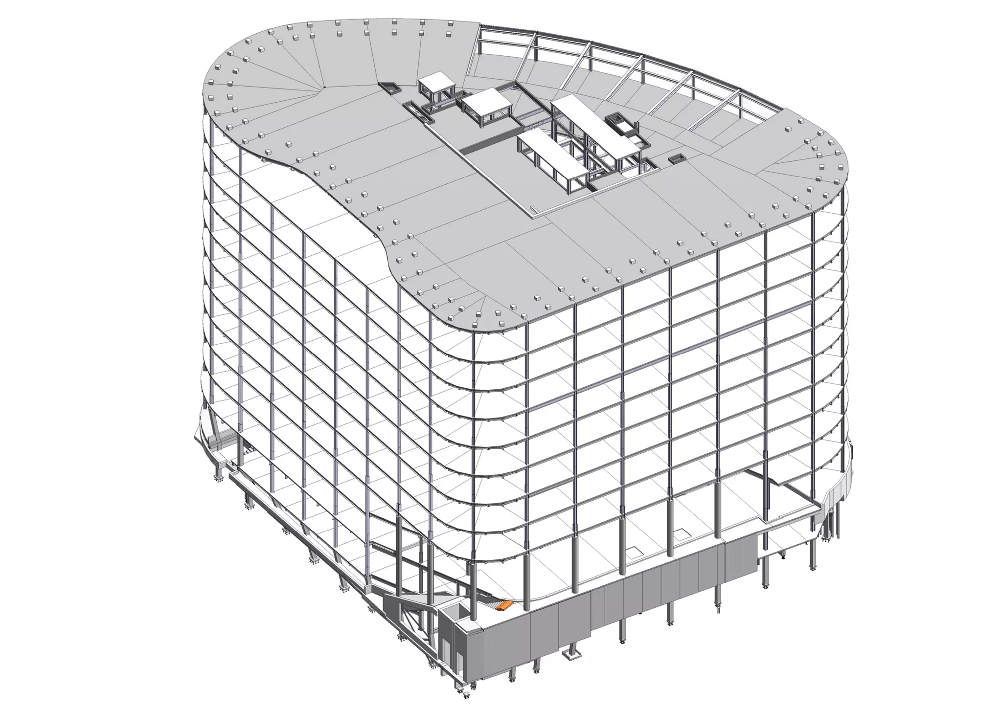
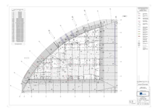
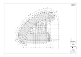
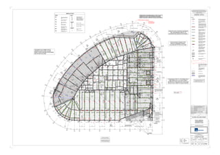
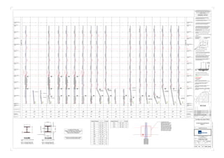
14
9 8 7 6 5 4
15
16
17
18
19
20
21
22
23
G
F
E
D
C
24
27
B
BRACING ELEVATION
'N'
BRACING ELEVATION
'A'
BRACING ELEVATION
'B'
BRACING ELEVATION
'C'
BRACING ELEVATION
'D'
BRACING ELEVATION
'E'
BRACING ELEVATION
'F'
BRACING ELEVATION
'H'
BRACING ELEVATION
'J'
BRACING ELEVATION
'G'
BRACING ELEVATION
'K'
BRACING ELEVATION
'P'
3
40
0601
6
0415
17
0415
16
0415
15
0415
13
0415
10
0415
9
0415
8
0415
7
0415
3
0415
4
0415
11
0415
12
0415
14
0415
2
0415
1
0410
2
0410
3
0410
4
0410
5
0410
2
0605
2
0604
1
0604
20
0603
1
0605
20
0604
17
0603
10
0602
18
0603
19
0603
14
0602
15
0602
17
0602
18
0605
1
0607
2
0607
PG28
PG24
PG28
PG25PG25
PG05
PG09
PG09
PG05PG28PG27
PG53PG42
5B
5B
5B
PG82
5B
5B
5B 5B
PG82
PG05
5B
PG82
PG04PG05
PG05
PG05
PG82
PG82 PG82
PG109
AC
AC
PG82
PG82
PG82
BE
BE
5B
PG82
PG04 PG04
PG82PG82
PG05
PG05
5B
PG05
BE
BE
BE
5B
PG109
PG04 PG04
PG05
PG05
PG05
PG05
PG82
PG82
PG82
5B
5B
PG82
5B
PG82
5B
5B
5B
PG24
PG27
PG24
PG27
PG27
PG27
PG24
PG24-C
PG24-C
PG05
PG05
PG05
PG24
PG05
PG05
PG05
PG05
PG05
PG05
PG05
PG05
PG05
PG05
PG05
PG29
SSL +8.425 m
SSL +8.425 m
SSL +8.425 m
VB
VB
VBVB
VB
VB
VB
VB
VB
VBVB
VB
VB
VB
VB
VBVB
VB
VB
VB
VB
Stair Core
Fire Lift 1
Goods Lift
PG05PG05
PG05
CB
5B5B5B
PG24
AB
BE
EA3A
Corus Comflor®
CF51 1.2
EA3A
Corus Comflor®
CF51 1.2
TOS +8.275 m
EA3A
TOS +8.275 m
EA3A
TOS +8.425 m
AB
PG39
PG39
PG108
PG39
B2
79
B2
80
B2
81
B2
82
B2
83
B2
115
B2
116
B2
101 B2
100 B2
77
B2
76
B2
75
B2
114
B2
112
B2
111
B2
113
B2
93
B2
91
B2
106
B2
109
B2
110
B2
104
B2
108
B2
105
B2
85
B2
86
B2
44
B2
46
B2
48
B2
50
B2
89 B2
92B2
90 B2
94
B2
111
B2
110
B2
78
B2
79
B2
80
B2
81
B2
82
B2
83
B2
103
B2
115
B2
116
B2
101 B2
100 B2
77
B2
99
B2
76
B2
75
B2
98
B2
114
B2
112
B2
111
B2
113 B2
97
B2
74
B2
73
B2
96
B2
93
B2
91
B2
107
B2
109
B2
110
B2
104
B2
108
B2
84
B2
85
B2
86
B2
102
B2
44
B2
46
B2
48
B2
50
B2
89 B2
92B2
90 B2
94
B2
111
B2
110
B2
119
Corus Comflor®
CF51 1.2
Corus Comflor®
CF51 1.2
B2
95
SSL +7.780 m
AB
AB
AB
RHS22F
RHS22F
RHS22F
RHS22F
RHS22F
RHS22F
* *
**
*
*
*
*
*
*
*
*
*
*
*
*
*
*
*
*
*
*
*
**
*
*
*
*
*
CB
5A5B
149
150
200
150
4865835
300
1570
150
36302751398
150
58511351504715
1910181340018772285354170330013591123300476150951300039442001856894300102815023261303
973200285020017771073
350465
216
15098515015044001502001100950
150
20011001050
150
20011001050
150150
33001501501050110020075295075
75
125
13001200
10502540206014002197
16851502238200270020028502001777107320028502751602
150
10501700
150
11001050150
15010501100200
100
1827110339845002295209
1400
1303590150
305567
47151501090150
150150
150150
1517
100 2050
400
2700 200
23820501812
2002001856844200
75
75
3751023
77
939105
150
10502400150
376510352550
1073
184
1949
18771173
1517
59933452056
45
150 150
150150 2482
1501090
45
150 150
150150
345020301570
150
835300
300501763
400
1877
200150
100100 100100 200200
200
2276
2150
2150
75 200
100100 100100 100100 100100
75 75
150
150 204
200 200
1875299
1720
SSL +8.425 m
SSL +8.425 m
150mm Thick
RC Structural
Slab
2020
3
450 150
150
315
235
270
550
820
313
595
1250
Corus Comflor®
CF51 1.2
AB
PG01 - Indicates steel beam and beam
reference. Top Flange to be -150
S.S.L. level, unless noted otherwise on
the Beam.
- Denotes steel shelf angle to
support metal deck edge and size
reference. See local sections for
angle orientation. Level to bearing face.
Beam Legend:
VB - Indicates vertical cross bracing bay.
Refer to Bracing Elevation drawing Nos.
0550 to 0552
- Indicates 250mm dia. service hole
through beam web. Hole to be at
mid depth unless noted otherwise.
Typically holes at 500mm centres,
unless noted otherwise.
- Indicates rectangular service hole
through beam web. Size 500x250mm
Deep. Hole to be at mid depth,
unless noted otherwise.
- Indicates rectangular service hole
through beam web. Size 750x250mm
Deep. Hole to be at mid depth,
unless noted otherwise.
- Indicates rectangular service hole
through beam web. Size 850x250mm
Deep. Hole to be at mid depth,
unless noted otherwise.
- Indicates rectangular service hole
through beam web. Size 300x250mm
Deep. Hole to be at mid depth,
unless noted otherwise.
- Denotes steel support plates to
metal deck edges and solid rc slabs.
See local sections for size and levels
to bearing face.
PG01
EA3A
TOS +25.250
RHS89D
FLT350-25
TOS +7.735
PG07
- Indicates upstand steel beam and beam
reference. Upstand Beam level shown as
TOB/TOBF (Top of Bottom Flange) unless
noted otherwise. Refer to relevant sections.
TOBF=19.950
- Denotes Span Direction, Thickness
and Type of New Floor Construction
Floors noted as (NWC)/(LWC)
to be metal deck concrete slabs.
B2
100 - Denotes Column Founding Level
and Individual Reference Number.
Refer to Drawing Nos. STR-10614-23-
0600 to 0606
- Indicates 1500mm Width Area designed
for 7.5 kN/m² 1500mm WIDE
- Denotes Concrete Upstands
- Denotes Steel Column with 50mm min.
Concrete Encasement.
- Denoted beams shall be
`NOT INTUMESCENT PAINTED` (NIP)
For Fireproofing to these beams refer to
Architects Details.
*
aterman
Scales @ A0
Drawn By
Designed By Checked By
Date
Project No
Drawing Status
Client
Title
Project
Amendments
DescriptionRev Date By
GENERAL NOTES
Works Order No
Pickfords Wharf Clink Street London SE1 9DG
United Kingdom
t +44 20 7928 7888 f +44 3333 444 501
mail@watermangroup.com www.watermangroup.com
This drawing should not be scaled. Dimensions to be verified on site.
Any discrepancies should be referred to the Engineer prior to work being put in hand.
This drawing is the property of Waterman Structures Limited and the drawing is issued
on the condition that it is not copied, reproduced, retained or disclosed to any
unauthorised person, either wholly or in part without the consent in writing of
Waterman Structures Limited
Pickfords Wharf Clink Street London SE1 9DG United Kingdom
t +44 20 7928 7888 f +44 3333 444 501
Publisher Zone Category Number Revision
As indicated
33 KING WILLIAM STREET
Designer Checker
SKD
H.B.REAVIS UK Ltd
CORE LAYOUT
LOWER GROUND GA
CONSTRUCTION
STR10614
Central:-Nt-lncswslProjectsSTR10614CAD3DWSLModelsWSL-10614-SA-33KWS-Central.rvt
0209GA 20 E02STR
FFL =
SSL =
TOS =
8.575
8.425
8.275
Unless Noted Otherwise
FOR FULL DETAILS SIZES OF PLATE BEAMS,
REFER TO DRAWING No. STR-SA-16-0002
Lower Ground - Structural Beam Schedule
Beam Ref Size
5A UB203x133x25
5B UB203x133x30
AB UC152x152x30
AB-C UC203x203x60
AC UC152x152x37
AE UC152x152x51
AE-C UC203x203x60
BE UC203x203x86
CB UC254x254x89
PG04 350x300x15/10mm Plate Beam
PG04-C 350x300x15/10mm Plate Beam
PG05 350x150x10/10mm Plate Beam
PG05-C 350x150x10/10mm Plate Beam
PG08-C 450x150x10/10mm Plate Beam
PG09 350x300x30/20mm Plate Beam
PG10 450x150x10/150x15/10mm Plate Beam
PG20 450x200x20/20mm Plate Beam
PG24 350x150x15/15mm Plate Beam
PG24-C 350x150x15/15mm Plate Beam
PG25 350x150x20/15mm Plate Beam
PG25-C 350x150x20/15mm Plate Beam
PG27 350x200x15/15mm Plate Beam
PG27-C 350x200x15/15mm Plate Beam
PG28 350x250x30/20mm Plate Beam
PG28-C 350x250x30/20mm Plate Beam
PG29 350x350x40/40mm Plate Beam
PG30 350x250x20/20mm Plate Beam
PG39 925x250x30/30mm Plate Beam
PG40 350x200x30/30mm Plate Beam
PG40-C 350x200x30/30mm Plate Beam
PG41-C 350x300x40/40mm Plate Beam
PG42 450x350x50/40mm Plate Beam
PG53 350x300x20/20mm Plate Beam
PG61 500x300x40/30mm Plate Beam
PG61-C 500x300x40/30mm Plate Beam
PG82 450x150x15/10mm Plate Beam
PG105-C 650x150x15/15mm Plate Beam
PG106 350x350x45/45mm Plate Beam
PG107 500x500x50/50mm Plate Beam
PG108 300x400x40/40mm Plate Beam
PG109 655x150x10/10mm Plate Beam
PG116 180x350x30mm Plate Beam
E02
STEEL CONSTRUCTION ISSUE UP TO GROUND
FLOOR ONLY
16.01.15 SGP
14
13
12
11
9 8 7 6 5 4 2 1
15
16
17
18
19
20
21
22
23
J
H
G
F
E
D
C
24
26
27
A
B
3
20.42°
5.61°
5.61°
5.61°
5.61°
5.61°
5.61°
5.61°
5.61°
5.61°
7.37°
5664
27.23°
27.23°
32.06°
8370
4675
8.23°
600060006000600060007318
73186000600060006000600060003000
5.61°
5.61°
27.23°
SSL +16.350 m
SSL +16.350 m
SSL +16.350 m
SSL +16.350 m
A= ?
A=?
A= ?
+16.520 m
+16.520m
+16.535 m
+16.535 m
+16.350 m
+16.530m
+16.540 m
A=?
A= ?
600060006000600060007318
73186000600060006000600060003000
1191
3729
1004
200
2050
400
2700
844
3630
2050
1028
300
894
400 2950
1050
1123
300
1703 354 4162
1135
973
2150
465
1423
1720
400
2850
200
2850
200
2850
200
2700
200
2163
1100
1073
1700
2520
2615
3450250
2197
1799
3540
835
835
2850200 200
1763
950
8.015° 8.015°
8.015°
8.015°
8.015°
8.015°
8.015°
8.015°
6.66°
8.015°
8.015°
5.70°
6.81°
6.81°
1.1°
5.70°
6.81°
1.11°
5.70°
6.81°
6.81°
6.81°
1.1° 5.70°
6.81°
6.81°
6.81°
1.1°
1.11°
0.52°
1.40°
1.40°
1.18°
1.40°
1.40°
1.18°
1.40°
1.40°
1.18°
0.23°
1.40°
0.23°
1.40°
0.23°
1.40°
1.40°
1.40°
1.17°
0.23°
1.40°
1.40°
1.40°
1.17°
0.23°
1.41°
1.40°
1.40°
1.17°
0.23°
1.40°
1.40°
1.40°
1.17°
0.23° 1.40°
1.40°
1.40°
1.17°
0.23°
1.40°
1.40°
1.40°
1.17°
0.23°
1.40°
1.40°
1.40° 3.80°
1.35°
837
837
837
837
837
837
837
837
837
837
2524.04°
14001997
14061400
1307
1990
1400
1302
1050
231
1050
2400
1856
1135
654 1153
950250
794
885
465 1073 1777
1050
1050
1412
1100
585
1359
973
10
4851
4849
3111
1001
950
478
3511
60003128579
1500
1654
TYPICAL
838
838
838
5.70°
27.23°
32.06°
13.61°
1000
1000
837
836
836
6.81°
6.81°
837
837
TYPICAL
TYPICAL
TYPICAL
TYPICAL
TYPICAL
TYPICAL
TYPIC
AL
TYPICAL
TYPICAL
TYPICAL
TYPICAL
TYPICAL
TYPICAL
TYPICAL
TYPICAL
TYPICAL
TYPICAL
1500 7318
4586
231
581
6.81°
1.11°
609
aterman
Scales @ A0
Drawn By
Designed By Checked By
Date
Project No
Drawing Status
Client
Title
Project
Amendments
DescriptionRev Date By
GENERAL NOTES
Works Order No
Pickfords Wharf Clink Street London SE1 9DG
United Kingdom
t +44 20 7928 7888 f +44 3333 444 501
mail@watermangroup.com www.watermangroup.com
This drawing should not be scaled. Dimensions to be verified on site.
Any discrepancies should be referred to the Engineer prior to work being put in hand.
This drawing is the property of Waterman Structures Limited and the drawing is issued
on the condition that it is not copied, reproduced, retained or disclosed to any
unauthorised person, either wholly or in part without the consent in writing of
Waterman Structures Limited
Pickfords Wharf Clink Street London SE1 9DG United Kingdom
t +44 20 7928 7888 f +44 3333 444 501
Publisher Zone Category Number Revision
1 : 100
33 KING WILLIAM STREET
Designer Checker
SKD SEPT 2014
H.B.REAVIS UK Ltd
SLAB EDGES
FIRST FLOOR
TENDER
STR10614
Central:-Nt-lncswslProjectsSTR10614CAD3DWSLModelsWSL-10614-SA-33KWS-Central.rvt
0327SA 20 C02STR
C01 ISSUED FOR T1 STEELWORK TENDER10.09.14 MRA
C02 ISSUED FOR T2 STEELWORK TENDER01.12.14 SKD
ABBREVIATIONS
F.F.L. - Denotes Finished Floor Level.
S.S.L. - Denotes Structural Slab Level.
T.O.S. - Denotes Top Of Steel level.
T.O.B.F. - Denotes Top Of Bottom Flange level.
T.O.C. - Denotes Top Of Concrete level.
B.O.C. - Denotes Bottom Of Concrete level.
C.L.O.S. - Denotes Centre Line of Steel level.
LEVELSFORCES
- Indicates moment connection and
factored ultimate design moment
(kNm).
M=100
- Indicates end vertical reaction.
Reaction is factored (kN).
R=125
- Indicates end horizontal
reaction. Reaction is factored
(kN).
H=125
- Indicates axial reaction.
Reaction is factored (kN).
A=200
- Indicates torsional moment
connection. Moment is ultimate
and factored (kNm).
T=100
- Indicates horizontal moment
connection and factored ultimate
design moment (kNm).
HM=100
- Indicates amount of pre-camber
to be applied to beam.
PC=15
COLUMNS
- Denotes Column Carried.
- Denotes Column Capped by beam over.
- Denotes Column Stopped at T.O.S. level.
- Denotes Column Hanging.
CONCRETE
N.W.C. - Denotes Normal Weight
Concrete.
L.W.C. - Denotes Light Weight Concrete
CCa
CC
CS
CH
CONNECTIONS OF STEELWORK AROUND LIFT SHAFTS IS NOT TO
PROTRUDE INTO THE LIFT SHAFTS BEYOND THE SLAB EDGE
WHERE A SLAB EXISTS, OR BEYOND THE STEEL SECTION WIDTH.
- Indicates 30Ø Holes along highlighted
beams placed @ 200mm Centres.
Holes to be provided centrally onto the
beam depth
AN ALLOWANCE HAS BEEN MADE FOR A LOAD
FROM RECEPTION WALLS OF 30kN/m. LENGTH
AS SHOWN ON JRA, AS OF 22/10/2014
14
13
12
11
9 8 7 6 5 4 2 1
15
16
17
18
19
20
21
22
23
J
H
G
F
E
D
C
24
26
27
A
A
B
B
E 532830.069 m
N 180764.785 m
E 532831.852 m
N 180721.596 m
20.42°
5.61°
5.61°
5.61°
5.61°
5.61°
5.61°
5.61°
5.61°
5.61°
7.37°
E 532827.684 m
N 180713.895 m
5664
15003010
27.23°
27.23°
32.06°
8370
2570
49536
61270
10337
12708
13254675
8.23°
PG02
PG02
PG70PG65
PG38PG28PG63
5B
5B
5B
5B
5B
5B 5B
PG08
PG47
PG08
PG08
PG08
PG47
BE
BE
BE
BE
5B
PG10 PG10
PG08
PG08
5B
PG08
BE
BE
BE
BE
PG08
PG10
PG12
PG08
PG08
PG08
PG08
5B
5B
5B
5B
5B
5B
EA3A
EA3A
PG20
PG114 PG114 PG114 PG62
PG20
PG111
PG33
PG33
PG111
PG10
PG10
PG10
PG62
PG10PG47PG47PG47
PG08
PG08
BE
PG47
AB
PG68PG68PG68PG68PG69
PG110PG08
PG48
PG48
RHS50D
PG20
PG20
PG20
PG08
PG08
PG117
PG47
PG47
PG47
PG69
PG69
PG69
PG69
PG69
AB
PG56
AB
AB
AB
AB
AB
PG08
PG08
PG110
PG110
PG110
PG110
PG15
PG08
PG47
PG47
PG47
AB
AB
AB
PG08
PG08
PG110PG08
PG110PG08
PG110PG08
PG110PG08
PG110PG08
PG110PG08
PG110PG08
PG110PG08
PG112
PG113
AB
5B 5B5B
AB
AB
AB
AB
AB
AB
AB
AB
AB
AB
AB
AB
AB
AB
AB
AB
AB AB
AB
AB
PG20
AB
600060006000600060007318
73186000600060006000600060003000
5.61°
5.61°
27.23°
3
PG15
PG08
PG20 PG12
PG20
PG12
PG12
PG44
PG47
PG47
PG105
PG20
PG25
PG12
PG25
PG20
PG10
PG20
PG12
PG12
PG25
PG25
PG11
PG10
PG47
PG47
PG47
PG105
PG12
PG12
PG12
PG12
PG12
PG12
PG12
PG12
PG10
PG47
PG10
PG08
PG72
PG08
PG08
PG08PG113
PG112
PG12
PG10
PG15
AB
AB
PG117
PG117
PG117
PG117
AB
AB
AB
AB
AB
AB
PG117
AB
PG37-C
PG117
AB
PG37-C
PG08
PG08
PG08
PG08
PG08
5B
PG46
PG82
PG82
PG82
PG82
PG82
PG31 PG31
PG82
PG82
PG09PG09
PG82
PG82
PG82
PG82
PG115
Proposed Piled Raft Foundation
Proposed RC Retaining Wall
PG31
SSL +12.360 m
SSL +12.260 m
SSL +12.260 m
SSL +12.700 m
SSL +12.700 m
SSL +12.700 m
SSL +12.360 m
SSL +12.360 m
SSL +12.360 m
SSL +12.360 m
SSL +12.700 m
SSL +12.700 m
SSL +12.700 m
SSL +12.360 m
SSL +12.700 m
325mm Thick RC Slab
VB
VB
VBVB
VB
VB
VB
VB
VB
VBVB
VB
VB VB
VB
VBVB
VB
VB
VB
VB
150mm Thick
RC Structural
Slab
150mm Thick RC
Structural Slab
150mm Thick
RC Structural
Slab
Proposed Precast 300mm Thick Twin
Wall construction, under Metal Deck Slab.
Rebar to be placed into Cavity of PC
Twinwall and cast into new Metal Deck
Slabs
Ex. Retaining Wall
150mm Thick RC
Structural Slab
For Details of Proposed Piled Raft,
refer to Drawing No. 10614 SA 10 0067
TransferBeam
Transfer Beam
TransferBeam
(ConcreteEncased)
All CHS's to be concrete filled and
Architecturally finished intumescent paint.
A= 1800kN
A=1800kN
A= ?
A= ?
A= ?
A= ?
A= ?
A= ?
A= ?
A= ?
A= ?
A= ?
A= ?
A= ?
A= ?
A= ?
For Additional Details to Public
Entrance Stairs and Lift, refer to
Drawings STR SA 24 0550 & 0551
Stair Core
Fire Lift 1
Goods Lift
Concrete Encasement
to External Columns
PBG10-C
PG56
PG82
PG82
PG82
PG82
PG62
PG117
PG08
PG10-C
AB-C
AB-C
AB-C
AB-C
AB
AB
AB
PG117
AB
AB
PG08
PG08
PG15
PG20
PG08
PG08
PG10
PG10
200mm RC
Upstand Wall
Proposed Precast
300mm Thick Twin Wall
construction, under.
Proposed Precast
300mm Thick Twin Wall
construction, under.
+12.550m
+12.210 m
PG60
PG54
PG28
PG54
PG54
+12.607m
PG08
PG47
PG62
EA3A
EA3A
+12.550 m
1
0420
2
0420
3
0420
4
0420
5
0420
6
0420
7
0420
8
0420
26
0420
9
0420
10
0420
11
0420
12
0420
13
0420
14
0420
15
0420
17
0420
18
0420
19
0420
22
0420
23
0420
24
0420
25
0420
28
0420
27
0420
UA7A
+12.550
21
0420
20
0420
16
0420
29
0420
AB
Piled Raft Extension In Abeyance.
EA3A
31
0420
5B
150mm Thick
RC Structural
Slab
150mm Thick RC
Structural Slab
PG12
PG12
32
0420
AB
AB
325mm Thick
RC Slab
FLT225x20
TOS +12.550 m
AB
EA3A
TOS +12.210 m
New Lift Core
30
0420
(Concrete Encased)
EA3A
TOS +12.010 m
TOS+12.550m
A= ?
A=?
A= ?
A=?
Where assume
Unless Noted Otherwise
A= 1000kNA= ?
TOBF +12.800 m
1
0421
39
0421
Proposed RC Retaining Wall
PG37-C
B2
69 B2
70
B2
71
B2
72
B2
40
B2
44
B2
46
B2
35B2
34
B2
17
B2
01
B2
39
B2
41
B2
61
B2
04
G
162G
163
B2
33
B2
27
B2
25
B2
23
B2
05
B2
06
B2
07
B2
01
B2
78
B2
79
B2
80
B2
81
B2
83
B2
103 B2
115
B2
116
B2
101
B2
100 B2
77
B2
75
B2
112
B2
113 B2
97 B2
74
B2
95
B2
91
B2
106
B2
107
B2
104
B2
105
B2
84
B2
85
B2
86
B2
102
B1
136
B2
69 B2
70
B2
71
B2
72
B2
46
B2
04
B2
08
B2
09
B2
35B2
34B2
33B2
32B2
31B2
30B2
29
B2
27
B2
26
B2
25
B2
21
B2
20
B2
19
B2
18
B2
17
G
164
B2
02
B2
36
B2
69 B2
70
B2
71
B2
72
B2
40
B2
44
B2
46
B2
35B2
34
B2
17
B2
14
B2
01
B2
39
B2
41
B2
60
B2
61
B2
38
B2
04
G
162G
163
B2
33
B2
27
B2
25
B2
23
B2
05
B2
06
B2
07
B2
01
B2
15
B2
78
B2
79
B2
80
B2
81
B2
82
B2
83
B2
115
B2
116
B2
101
B2
100 B2
77
B2
99
B2
76
B2
75
B2
98B2
114
B2
112
B2
111 B2
113 B2
97 B2
74
B2
73
B2
96
B2
95B2
93
B2
91
B2
106
B2
107 B2
109
B2
110B2
104
B2
108
B2
105
B2
84
B2
85
B2
86
B2
102
B1
136
B2
69
B2
88
B2
70
B2
71
B2
72
B2
46
B2
48
B2
50
B2
04
B2
08
B2
09
B2
10
B2
35B2
34B2
33B2
32B2
31B2
30B2
29
B2
27
B2
26
B2
25
G
165
B2
21
B2
20
B2
19
B2
18
B2
17
B2
16
G
164
B2
57
B2
02
B2
36
25
10
27.23°
13.61°
G
167
1350
1350
G
166
TransferBeam
24.04°
32.06°
All Composite Slabs at this level to be 120
minute Fire rating. Solid RC Slabs at Grids
12 to 20, A to B, 240 minute fire rating
PG15PG54
TOS+12.040m
33
0420
PG10 A= ?
Transfer Beam
EA3A
EA3A
TOS +12.040 m
TOS+12.110mTOS+12.110m
PG08
R=400R=400
AB-C
R=270R=270
RHS22F
RHS22F
RHS22F
RHS22F
RHS22F
RHS22F
AB
TOBF+12.375
AB
24
0421
PG08
PG08
PG08
PG08
*
*
*
*
TOS +12.607 m
TOS+12.607m
TOS +12.607 m
TOS +12.607 m
TOS +12.607 m
TOS +12.607 m
TOS
+12.607 m
TOS
+12.607 m
TOS
+12.607m
TOS
+12.607m
TOS +12.607 m
TOS+12.607m
TOS+12.607m
TOS +12.607 m
TOS+12.550m
AB
+12.607 m
TOS+12.607m
TOS+12.607m
TOS +12.625 m
TOS +12.607 m
TOS +12.607 m
TOS
+12.607 m
TOS+12.607m
TOS+12.607m
TOS+12.607m
TOS+12.607m
+12.607m
+12.607m
TOS+12.607m
cs
cs
(Concrete Encased) Transfer Beam
(Concrete Encased)
TOS
+12.607 m
A=500
A=500
A=500
A=500
A=500
A=500
A=1800kN
A=500
A=500
A=500
A=1800kN
**
**
**
**
**
#
#
#
#
#
#
#
PG117
R=800 R=800
R=800 R=800
35
0421
TOBF +12.550 TOBF +12.550
TOBF +12.550
TOBF+12.550
TOBF+12.210TOS+12.550TOBF+12.040
PG08 PG08 PG08PG08PG08 PG08 PG08 PG08 PG08
5B
PG38-T
AB
AB
ABPG122
2004100200
35001150
48502500
37
0421
PG18
200200
PG119
SSL +11.430 m
TOBF+11.760
TOBF+11.760
TOBF +11.760
TOBF +11.760
38
0421
PG119
6
0620
950500750
550 950 950
1025 950 950 950 550 1025950 950 1025 950 950 550
925 1150 925 500500 500
105630
415
925925925775
925925
133
5009259255005001150925500500500
500
925
925
500
925
PG33
1145
1250
500
500
500
1250
300014901510151014903000
16.03°
16.03°
15.79°11.74°
0.22°
2.81°
2.81°
950
1250
950
500
500
500
950
1200
925
500
500
500
500
500
500
500
925
925
925 500500 500500 500 500 500 925
925 1150 925
925 925 650
500 500 500 500 500500500500
1000500500500
950950
950500925925500500
1230 950 820
925895925 925 5751025950950 1025
950950
925925500500500500500500
925925
3000 3000 3000 3000 2990 214616001400
5005005001295
1150925
1300
1150
925500500
5091
1017
5501750700
600
600
600
600
2.81°
5.61°
4.02°
2.81°
1073 20771173 1877
925
925
500
500
950
975
925
925
500
925925500500500500500500950950500925925500500
2004650200
3
0421
5001434
10009509501100
500
R=800
R=800 R=800
R=800
TOS +12.607 m
TOS +12.210 m
TOS +12.700 m TOS +12.700 m TOS +12.700 m
TOS
+12.700m
TOS+12.550m
TOS+12.550m
TOS +12.210 m
TOS +12.550 m
TOS +10.795 m
TOS+12.200m
TOS+12.040m
TOS +12.040 m
TOS+12.030mTOS+12.030m
TOS+12.030m
TOS+12.030m
TOS+12.030m
TOS+12.040m
TOS +12.700 m
TOS +12.550 m
TOS+12.550m
TOS +12.607 m
TOS+12.607m
TOS+12.607m
TOS+10.867m
PG05
2
0421
CS
CS
CCa
CS
CCa
CS
CS
CS
TOBF+11.760
*
TOS +12.700m
TOS +12.700m
TOS+12.200mTOS+12.200m
TOS+12.020m
TOS +11.760 m
TOS+11.760m
TOS+11.760m
TOS +11.760 m
TOS+12.210m
CS
AB
PG12
TOS+12.110m
TOS +12.210 m
TOS +12.210 m
4
0421
EA2G
EA2G
TOS +12.210 m
TOS +12.210 m
TOS+12.110m
M=2000kN
V=800kN
M=60kNm
M=60kNm
M=60kNm
M=60kNm
M=60kNm
M=90kNm
M=90kNm
M=90kNm
M=90kNm
M=90kNm
M=90kNm
M=90kNmM=90kNm
M=90kNm
M=90kNm
M=90kNm
M=90kNm
M=90kNm
M=90kNm
M=90kNm
M=90kNm
M=90kNm
M=90kNm
M=90kNmM=90kNm
M=60kNm
M=60kNm
M=60kNm
M=60kNm
M=60kNm
M=60kNm
M=60kNm
M=60kNm
M=60kNm
M=60kNm
M=60kNm
M=60kNm
M=60kNm
M=60kNm
M=60kNm
M=60kNm
M=60kNm
M=60kNm
M=150kNm
M=150kNm
M=150kNm
M=150kNm
M=150kNm
M=150kNm
Concrete slab 300mm thk.
Column unrestrained in the
W-E direction between
2nd floor & Basement during
construction. Steel contractor
to make all allowances & provisions
for temporary case.
End of beam to be
supported off existing
diaphragm wall
PG10-C
A= 250kN
A= 250kN
A= 250kN
A= 250kN
A=250kN
A=250kN
A=250kN
A=250kN
A=250kN
A=250kN
A=250kN
A=250kN
#
#
#
#
A= 250kN
A= 250kN
A= 250kN
A= 250kN
A= 250kN
A= 250kN
A= 250kN
A= 250kN
A=250kN
A= 250kN
A=250kN
A=250kN
#
#
#
#
#
#
#
PG08
PG08
PG08
PG08
PG08
TOS+12.325m
TOS+12.325m
TOS+12.325m
TOS+12.550m
TOS+12.544m
5009259255091000
389500500
950950253
1488
PG08
PG08
1256
1539
PG01
- Indicates steel beam centre line and
beam reference. Top Flange to be -150
S.S.L. level, unless noted otherwise.
- Denotes steel shelf angle to support metal
deck edge and size reference. See local
sections for angle orientation.
Beam Legend:
PG01
- Indicates upstand steel beam and beam
reference. Upstand Beam level shown as
TOB/TOBF (Top of Bottom Flange) unless,
noted otherwise. Refer to relevant sections.
- Indicates 250mm dia. service hole
through beam web. Hole to be at
mid depth unless noted otherwise.
Typically holes at 500mm centres,
unless noted otherwise.
- Indicates rectangular service hole
through beam web. Size 500x250mm
Deep. Hole to be at mid depth,
unless noted otherwise.
- Indicates rectangular service hole
through beam web. Size 750x250mm
Deep. Hole to be at mid depth,
unless noted otherwise.
- Indicates rectangular service hole
through beam web. Size 850x250mm
Deep. Hole to be at mid depth,
unless noted otherwise.
- Indicates rectangular service hole
through beam web. Size 300x250mm
Deep. Hole to be at mid depth,
unless noted otherwise.
- Denotes steel support plates to metal
deck edges and solid rc slabs.
See plans and local sections for size
and levels.
- Denotes Span Direction, Thickness
and Type of New Floor Construction
Floors noted as (NWC)/(LWC)
to be metal deck concrete slabs.
B2
100 - Denotes Column Founding Level
and Individual Reference Number.
Refer to Drawing Nos. STR-10614-23-
0600 to 0606
- Indicates 1500mm Width Area designed
for 7.5 kN/m² 1500mm WIDE
- Denotes Concrete Upstands
- Denotes Steel Column with 50mm min.
Concrete Encasement.
- Indicates vertical cross bracing bay.
Refer to Bracing Elevation drawing Nos.
0550 to 0552
VB
50mm Dia. Coupler to be welded onto column
flange, centrally placed to receive H32 Rebar to
provide tie provision. H32 to be fully lapped in
the slab.
FW 15mm to be provided all around coupler
perimeter.
**
- 30mm Dia. holes along highlighted
beams placed @ 200mm c/c.
Hole to be provided centrally onto
the beam depth.
#
- Light weight concrete.
- Normal weight concrete.
aterman
Scales @ A0
Drawn By
Designed By Checked By
Date
Project No
Drawing Status
Client
Title
Project
Amendments
DescriptionRev Date By
GENERAL NOTES
Works Order No
Pickfords Wharf Clink Street London SE1 9DG
United Kingdom
t +44 20 7928 7888 f +44 3333 444 501
mail@watermangroup.com www.watermangroup.com
This drawing should not be scaled. Dimensions to be verified on site.
Any discrepancies should be referred to the Engineer prior to work being put in hand.
This drawing is the property of Waterman Structures Limited and the drawing is issued
on the condition that it is not copied, reproduced, retained or disclosed to any
unauthorised person, either wholly or in part without the consent in writing of
Waterman Structures Limited
Pickfords Wharf Clink Street London SE1 9DG United Kingdom
t +44 20 7928 7888 f +44 3333 444 501
Publisher Zone Category Number Revision
As indicated
33 KING WILLIAM STREET
OR JPT
MRA/SKD JULY 2014
H.B.REAVIS UK Ltd
STEEL GENERAL
ARRANGEMENT
GROUND FLOOR
CONSTRUCTION
STR10614
Central:-Nt-lncswslProjectsSTR10614CAD3DWSLModelsWSL-10614-SA-33KWS-Central.rvt
0110SA 20 E04STR
1 : 100
B01 STAGE D28.07.14 MRA
FFL =
SSL =
TOS =
+150
As Shown
-150
Unless Noted Otherwise
SURVEYED LINE OF EXISTING DIAPHRAGM
WALL AND IMPERFECTIONS OF ITS
INCORPORATION REMAIN WITHSTANDING.
C01 ISSUED FOR T1 STEELWORK TENDER10.09.14 MRA
STUB BEAMS EXTENT TO THE PERIMETER OF
GRID LINES 24 to 27; 8 to 14 & H to GRID 2.
SETTING OUT TO BE ADJUSTED TO SUIT SLAB
PROFILE FACET, REFER TO STAGE D REPORT
C02 ISSUED FOR T2 STEELWORK TENDER01.12.14 SKD
IN ABEYANCE (PILES,
PILECAPS AND BASEPLATES
TO BE COORIDINATED WITH
TFL BANK STATION WORK).
FOR LOCATION OF SHEAR PLATES
REFER TO DRAWINGS STR10614-
SA-23-0609 AND STR10614-SA-23-0620
FOR SHEAR PLATE CONNECTION OF
CONCRETE SLAB TO STEEL COLUMN,
REFER TO WSL'S DRAWING STR-SA-230609
AND STR10614-SA-23-0620.
E01
STEEL CONSTRUCTION ISSUE UP TO GROUND
FLOOR ONLY
19.12.14 MRA
E02
STEEL CONSTRUCTION ISSUE UP TO GROUND
FLOOR ONLY
16.01.15 MRA
E03
STEEL CONSTRUCTION ISSUE UP TO GROUND
FLOOR ONLY
23.01.15 SKD
E04
STEEL CONSTRUCTION ISSUE UP TO GROUND
FLOOR ONLY. EXISTING RETAINED STRUCTURE
OMITTED FROM PREVIOUS REVISION.
27.01.15 SKD
150mm Thick
Structural Slab
SSL +8.425 m
Lower Ground Floor
PG42
PG28
EA3A
EA3A
50mm Thick Structural
Slab Topping
100x200x10 Unequal
Angle to be Cut Down
50mm.
15mm Fillet Weld
150mm Thick
Structural Slab
Lower Ground Floor
PG05
PG05
SSL +8.425 m
AB
150
150mm Thick
Structural Slab
SSL +8.425 m
Lower Ground Floor
PG53
PG05 TOBF +8.275 m
150mm Thick
Structural Slab
SSL +8.425 m
Lower Ground Floor
PG42
5B
EA3A
50mm Thick RC
Structural Slab Topping
100x200x10 Unequal
Angle to be Cut Down
50mm.
15mm Fillet Weld
SSL +8.425 m
Lower Ground Floor
Loading Bay
PG39
AE
TOS +7.380 m
400mm Thick
Structural Slab
150mm Thick RC
Composite Structural Slab
150mm Thick
RC Upstand Wall
400mm Thick
RC Structural Slab
2x10mm thick stiffener
plates @ 200 c/c
Studs @ 200 c/c 30Ø Holes placed @
200mm Centres thro' Beam
Web to receive Rebar
55
TOS +8.275 m
150mm Thick RC
Composite Structural Slab
150mm Thick
RC Upstand Wall
PG39
400mm Thick
RC Structural Slab
SSL +7.780 m
Loading Bay
Lower Ground Floor
SSL +8.425 m
2x10mm thick
stiffener plates
@ 200 c/c
Studs @ 200 c/c
55
30Ø Holes placed @
200mm Centres thro' Beam
Web to receive Rebar
400mm Thick
RC Structural Slab
150mm Thick
RC Slab
SSL +7.780 m
Loading Bay
150mm Thick
RC Upstand Wall
Lower Ground Floor
PG39
SSL +8.425 m
2x10mm thick
stiffener plates
@ 200 c/c
Studs @ 200 c/c
TOS +8.275 m
55
30Ø Holes placed @
200mm Centres thro' Beam
Web to receive Rebar
400mm Thick
RC Structural Slab
150mm Thick
RC Slab
SSL +7.780 m
Loading Bay
150mm Thick
RC Upstand Wall
Lower Ground Floor
PG39
2x10mm thick
stiffener plates
@ 200 c/c
Studs @ 200 c/c
SSL +8.425 m
TOS +8.275 m
30Ø Holes placed @
200mm Centres thro' Beam
Web to receive Rebar
55
400mm Thick
RC Structural Slab
SSL +7.780 m
Loading Bay Lower Ground Floor
PG108
TOS +7.640 m
B
300
140300
400
290
SSL +7.780 m
30Ø Holes along highlighted beams
placed @ 200mm Centres.
150mm Thick
Structural Slab
SSL +8.425 m
Lower Ground Floor
150
150mm Thick
Structural Slab
SSL +8.425 m
Lower Ground Floor
PG24
150
150mm Thick
Structural Slab
SSL +8.425 m
Lower Ground Floor
PG27
PG28
150mm Thick
Structural Slab
SSL +8.425 m
Lower Ground Floor
PG27
PG27
150mm Thick
Structural Slab
Lower Ground Floor
PG25
SSL +8.425 m
TOS +8.275 m
150
150mm Thick
Structural Slab
SSL +8.425 m
Lower Ground Floor
PG25 PG24-C
150mm Thick
Structural Slab
SSL +8.425 m
Lower Ground Floor
PG04
PG24-C
150mm Thick
Structural Slab
Lower Ground Floor
PG09
SSL +8.425 m
TOS +8.275 m
200
SSL +8.425 m
SSL +7.780 m
Loading Bay
Lower Ground Level
150mm Thick
Structural Slab
150mm Thick
Structural Wall
400mm Thick
Structural Slab
Void Former
PG39
TOS +8.275 m
Varies
150mm Thick
RC Slab
30Ø Holes placed @
200mm Centres thro' Beam
Web to receive Rebar
55
150mm Thick
Structural SlabLower Ground Floor
PG107
SSL +8.425 m
EA3C
EA3C
100x200x10 Unequal
Angle to be Cut Down
50mm.
15mm Fillet Weld
150mm Thick
Structural SlabLower Ground Floor
PG61-C
PG105-C PG105-C
EA3AEA3A
SSL +8.425 m
TOS +8.425 m
95
100x200x10 Unequal
Angle to be Cut Down
50mm.
15mm Fillet Weld
EA2G EA2G
PG42
SSL +8.425 m
150mm Thick
Structural Slab
Lower Ground Floor
50mm Thick RC
Structural Slab Topping
TOS +8.375 m
100x200x10 Unequal
Angle to be Cut Down
50mm.
15mm Fillet Weld
aterman
Scales @ A0
Drawn By
Designed By Checked By
Date
Project No
Drawing Status
Client
Title
Project
Amendments
DescriptionRev Date By
GENERAL NOTES
Works Order No
Pickfords Wharf Clink Street London SE1 9DG
United Kingdom
t +44 20 7928 7888 f +44 3333 444 501
mail@watermangroup.com www.watermangroup.com
This drawing should not be scaled. Dimensions to be verified on site.
Any discrepancies should be referred to the Engineer prior to work being put in hand.
This drawing is the property of Waterman Structures Limited and the drawing is issued
on the condition that it is not copied, reproduced, retained or disclosed to any
unauthorised person, either wholly or in part without the consent in writing of
Waterman Structures Limited
Pickfords Wharf Clink Street London SE1 9DG United Kingdom
t +44 20 7928 7888 f +44 3333 444 501
Publisher Zone Category Number Revision
1 : 20
33 KING WILLIAM STREET
Designer Checker
MRA/SKD SEPT '14
H.B.REAVIS UK Ltd
LOWER GROUND FLOOR
SECTIONS
SHEET 1
CONSTRUCTION
STR10614
Central:-Nt-lncswslProjectsSTR10614CAD3DWSLModelsWSL-10614-SA-33KWS-Central.rvt
0415SA 21 E04STR
C01 ISSUED FOR T1 STEELWORK TENDER10.09.14 MRA
Section 1 Section 2 Section 3 Section 4 Section 5 Section 6
Section 7
Section 8
Section 9
Section 10 Section 11 Section 12
Section 13 Section 14 Section 15 Section 16 Section 17 Section 18
Section 19
1. For locations of Sections, refer to Drawing STR-SA-20-0109
Section 20
Section 21
INTERFACE BETWEEN SOLID SLAB, ABOVE AND BELOW THE
LOADING BAY AND THE ADJACENT METAL DECK SLAB/CORE
AREA YET TO BE DEVELOPED.
STEELWORK CONTRACTOR TO ALLOW FOR THE FOLLOWING
TO BE INCLUDED TO STEEL BEAMS ALONG THAT INTERFACE.
- 2x50Ø HOLES @ 150mm C/C THROUGH BEAM WEB.
- SHELF ANGLES TO BOTH SIDES OF BEAMS, TO BE WELDED
CONTINUOUSLY TO WEBS.
- PLATE STIFFENERS TO BOTH SIDES OF BEAMS @ 1m. C/C's
C02 ISSUED FOR T2 STEELWORK TENDER01.12.14 SKD
2. FOR BEAM SECTION SIZES, REFER TO DRAWING No. 0002
STEEL TO STEEL CONNECTIONS NOT SHOWN ON THE
PRESENT DRAWING. DESIGN AND DETAILING IS TO MAIN
CONTRACTOR RESPONSIBILITY.
SUBJECT TO ENGINEERS APPROVAL.
E01
STEEL CONSTRUCTION ISSUE UP TO GROUND
FLOOR ONLY
19.12.14 MRA
E02
STEEL CONSTRUCTION ISSUE UP TO GROUND
FLOOR ONLY
16.01.15 SGP
E03
STEEL CONSTRUCTION ISSUE UP TO GROUND
FLOOR ONLY
23.01.15 SKD
E04
STEEL CONSTRUCTION ISSUE UP TO GROUND
FLOOR ONLY. EXISTING RETAINED STRUCTURE
OMITTED FROM PREVIOUS REVISION.
27.01.15 SKD
B2
01
UKC254x254x89UKC254x254x89UKC254x254x89UKC254x254x89
BP4
+3.860 m
350x25mmT&B300x20WPlateColumn350x25mmT&B300x20WPlateColumn
ConcreteEncasement
+19.500 m
+12.360 m
UC254x254x89
+3.860 m
UC305x305x198
B2
02
BP4
B2
03
UC305x305x198
+3.860 m
BP4
UC305x305x198
B2
04
+3.860 m
UC254x254x107UC254x254x107UC203x203x86UC203x203x86
BP9
350x45mmT&B260x45WPlateColumn
350x25mmT&B300x20WPlateColumn
Concrete Encased
ConcreteEncased
+19.500 m
+12.360 m
+7.812 m
UC254x254x107
UKC254x254x107UKC254x254x107UKC203x203x86UKC203x203x86
B2
05
BP13
F-1
+3.860 m
350x25mmT&B300x20WPlateColumn350x25mmT&B300x20WPlateColumn350x25mmT&B300x20WPlateColumn
ConcreteEncasedConcreteEncased
+19.500 m
+12.360 m
+8.275 m
UC254x254x107
B2
06
UKC203x203x86UKC203x203x86UKC254x254x107UKC254x254x107
BP4
E-1
+3.860 m
350x25mmT&B300x20WPlateColumn350x25mmT&B300x20WPlateColumn350x25mmT&B300x20WPlateColumn
ConcreteEncasedConcreteEncased
+19.500 m
+12.360 m
+8.275 m
UC254x254x107
B2
07
UKC203x203x86UKC203x203x86UKC254x254x107UKC254x254x107
BP4
D-1
+3.860 m
350x25mmT&B300x20WPlateColumn350x25mmT&B300x20WPlateColumn350x25mmT&B300x20WPlateColumn
ConcreteEncased
+19.500 m
+12.360 m
ConcreteEncased
+8.275 m
UC254x254x107
B2
08
UKC254x254x107UKC254x254x107UKC203x203x86UKC203x203x86
BP4
+3.860 m
350x25mmT&B300x20WPlateColumn350x25mmT&B300x20WPlateColumn350x25mmT&B300x20WPlateColumn
ConcreteEncased
+8.275 m
UC254x254x107
UKC254x254x89UKC254x254x89UKC254x254x89UKC254x254x107UKC254x254x132UKC305x305x198
B2
09
BP4
+3.860 m
UKC305x305x198
ConcreteEncased
+8.275 m
B2
10
UC305x305x283
+3.860 m
UC305x305x283
UC254x254x132UC254x254x107UC254x254x107UC254x254x107UC254x254x107
BP9
ConcreteEncased
Concrete Encased
+8.275 m
+12.000 m
B2
11
UC305x305x198
+3.860 m
UC305x305x198
UC254x254x107UC254x254x89UC254x254x89UC254x254x89UC254x254x89
BP9
ConcreteEncased
Concrete Encased
+8.275 m
+12.099 m
B2
12
BP1
+3.860 mUC203x203x86UC203x203x86
B2
13
UKC203x203x60
BP1
+2.760 m
UKC203x203x60
ConcreteEncased
+8.425 m
B2
14
UKC356x406x340
UKC305x305x198UKC254x254x132UKC254x254x107UKC254x254x89UKC203x203x86
UC356x406x340
BP9
+2.760 m
UC305x305x198
ConcreteEncased
+7.275 m
B2
15
UKC305x305x198UKC254x254x167UKC254x254x132UKC254x254x107UKC254x254x89UKC203x203x86
BP3
A-21
+3.860 m
UKC305x305x198
ConcreteEncased
+8.275 m
B2
16
UKC254x254x167UKC254x254x132UKC254x254x107UKC254x254x89UKC203x203x86
BP9
+3.860 m
UKC305x305x283
UC305x305x283
Concrete Encased
+8.100 m
B2
17
UC356x406x287
+3.860 m
UC305x305x198UC254x254x167UC254x254x132UC254x254x107UC254x254x107UC254x254x89
BP9
Concrete Encased
+7.810 m
B2
18
UC356x406x287
+3.860 m
UC254x254x167UC254x254x167UC254x254x132UC254x254x107UC254x254x107UC254x254x89
BP9
Concrete Encased
+12.375 m
+3.245 m
UC254x254x132UC254x254x132UC254x254x132UC254x254x167UC254x254x167UC254x254x167
BP9
Concrete Encased
+12.344 m
B2
19 B2
20
UC356x406x287
+3.245 m
UC254x254x89UC254x254x107UC254x254x132UC254x254x167UC254x254x167UC305x305x198
BP9
Concrete Encased
ConcreteEncased
+12.700 m
4 No. holes for M20 dia. locating bolts /anchors minimum .
Column bolts to be designed for the following:
i) Horizontal shear, the largest of national horizontal load equal to 1%
of axial load , or, horizontal component of the lowest storey of bracing.
ii) Tensile forces as noted on the column schedule.
the steelwork contractor must design all column baseplate connections
by such a time enable bolts and templates to be provided to the
concrete contractor to cast into the raft slab, if required, or locally
displaced slab reinforcement to avoid post drilled bolt locations.
The Contractor shall allow for any increase in size of baseplates to suit
the bolt design and arrangement. the sizes shown here are the
minimum required for bearing only.
9. C3 - Denotes column with C3 exposure point applied.
10. All concrete filled CHS` are to be intumescent painted for 120
minute
period Basement to Ground, and 90 minutes Ground to Roof level.
Column size varies. Columns
are to be positioned centrally
on the baseplate.
All columns to be centred
on baseplates unless
eccentricity shown.
4. All concrete filled hollow sections are to include 20mm Ø vent holes
located in diametrically opposite pairs in the ceiling void and floor void of
each level. drain holes are to be provided where division plates are
present. All holes to be temporarily plugged during concreting.
3. 1x50mm Ø grout hole is to be provided per 0.5m² of basplate, located
so as to not influence the bolt design. Where multiple grout holes are
required they are to be placed evenly on the baseplate area.
1. All internal concrete filled CHS columns to be high quality
Architectural finish intumescent painted with no joints or gaps visible
benchmark standard is 6 Bevis Marks, London.
2. The steel fabricator shall, based on experience of similar size projects,
make due allowance for baseplate sizes for all columns.
X - See table below
Y-Seetablebelow
Top of bolt to
extend above
F.F.L. -35mm
25
nominalgrout
U/Side
Baseplate
WELDS TO PLATE GIRDER COLUMN SECTIONS
TO BE:-
8mm F.W. - PLATES LESS THAN 40mm THICK
10mm F.W. - PLATES 40mm TO 60mm THICK
12mm F.W. - PLATES MORE THAN 60mm THICK
D
F
W
B
PG COLUMNS
ALL BASEPLATE DETAILS ARE
SUBJECT TO APPROVAL BY THE ARCHITECT IN
TERMS OF FLOOR FINISHES AND OTHER
ARCHITECTURAL CONSTRAINTS
5. Allowances is to be made for shear keys to baseplates to be provided
for all columns with "V=" noted.
Refer to Stage D report Clause 1.7 See Detail..A Drg.STR/SA/23/0610
6. Allowances is to be made for uplift baseplate detail noted in Stage D
report Clause 1.7.
All columns with "T=" noted. See Detail..B Drg.STR/SA/23/0610
7. Assume all fabricated columns are welded with 4 No. continuous fillet welds.
8. BASEPLATES:
Baseplate Reference X Y Thickness
BP1 270 270 25
BP3 525 525 70
BP4 425 425 40
BP6 625 625 100
BP7 700 700 100
BP8 675 675 60
BP2 380 380 40
BP6A 575 575 60
BP9 700 700 60
BP10 800 800 100
Baseplate Reference X Y Thickness
BP13 425 395 40
BP14 700 622 50
BP15 700 664 60
BP6B 575 575 70
BP5 525 525 50
Depth
FlangeThickness
FlangeThickness
Flange Width
Web Thickness
Flange Width
50mmConcreteEncasement
50 mm Concrete Encasement
WELDS TO PLATE GIRDER COLUMN SECTIONS
TO BE:-
8mm F.W. - PLATES LESS THAN 40mm THICK
10mm F.W. - PLATES 40mm TO 60mm THICK
12mm F.W. - PLATES MORE THAN 60mm THICK
PG-C COLUMNS
For details of the column
between the floor level and the
splice above please refer to
drawing STR-SA-23-0610 which
shows a divisional plate at floor
level and the column reducing in
size between the divisional plate
and the splice to match the size
of the column above the splice.
aterman
Scales @ A0
Drawn By
Designed By Checked By
Date
Project No
Drawing Status
Client
Title
Project
Amendments
DescriptionRev Date By
GENERAL NOTES
Works Order No
Pickfords Wharf Clink Street London SE1 9DG
United Kingdom
t +44 20 7928 7888 f +44 3333 444 501
mail@watermangroup.com www.watermangroup.com
This drawing should not be scaled. Dimensions to be verified on site.
Any discrepancies should be referred to the Engineer prior to work being put in hand.
This drawing is the property of Waterman Structures Limited and the drawing is issued
on the condition that it is not copied, reproduced, retained or disclosed to any
unauthorised person, either wholly or in part without the consent in writing of
Waterman Structures Limited
Pickfords Wharf Clink Street London SE1 9DG United Kingdom
t +44 20 7928 7888 f +44 3333 444 501
Publisher Zone Category Number Revision
As indicated
33 KING WILLIAM STREET
Designer Checker
SKD
H.B.REAVIS UK Ltd
STANCHION SCHEDULES
SHEET 1
CONSTRUCTION
STR10614
Central:-Nt-lncswslProjectsSTR10614CAD3DWSLModelsWSL-10614-SA-33KWS-Central.rvt
0600SA 23 E03STR
KEY PLAN
1 : 100
WSL COLUMN REFERENCE
COLUMN GRID LOCATION
SEVENTH FLOOR S.S.L.
+38.350m
EIGHTH FLOOR S.S.L.
+42.000m
NINTH FLOOR S.S.L.
+45.650m
UPPER ROOF LEVEL S.S.L.
+51.200m
ROOF LEVEL S.S.L.
+49.600m
SIXTH FLOOR S.S.L.
+34.700m
COLUMNTYPE
COLUMNTYPE
FIFTH FLOOR S.S.L.
+31.050m
FOURTH FLOOR S.S.L.
+27.400m
THIRD FLOOR S.S.L.
+23.750m
SECOND FLOOR S.S.L.
+20.100m
FIRST FLOOR S.S.L.
+16.350m
GROUND FLOOR S.S.L.
+12.700m
LOWER GROUND S.S.L.
+8.425m
Ex. BASEMENT S.S.L.
+3.835m
Ex. BASEMENT S.S.L.
+2.785m
SEVENTH FLOOR S.S.L.
+38.350m
EIGHTH FLOOR S.S.L.
+42.000m
NINTH FLOOR S.S.L.
+45.650m
UPPER ROOF LEVEL S.S.L.
+51.200m
ROOF LEVEL S.S.L.
+49.600m
SIXTH FLOOR S.S.L.
+34.700m
FIFTH FLOOR S.S.L.
+31.050m
FOURTH FLOOR S.S.L.
+27.400m
THIRD FLOOR S.S.L.
+23.750m
SECOND FLOOR S.S.L.
+20.100m
FIRST FLOOR S.S.L.
+16.350m
GROUND FLOOR S.S.L.
+12.700m
LOWER GROUND S.S.L.
+8.425m
Ex. BASEMENT S.S.L.
+3.835m
Ex. BASEMENT S.S.L.
+2.785m
WSL COLUMN REFERENCE
COLUMN GRID LOCATION
UNDERSIDE OF
BASEPLATE LEVEL.
BASEPLATE TYPE
UNDERSIDE OF
BASEPLATE LEVEL.
BASEPLATE TYPE
C01 ISSUED FOR T1 STEELWORK TENDER10.09.14 SKD
A=2750kN
A=2900kN
A=4050kN
A=4850kN
A=4000kNA=3200kNA=2700kNA=2050kNA=1250kN
A=3900kNA=3250kNA=2650kNA=2000kNA=1200kN
SPLICE
SPLICE
SPLICE
SPLICE
SPLICE
A=2350kNA=2050kNA=1600kNA=1200kNA=750kN
A=3000kNA=2850kNA=2200kNA=1750kNA=1100kN
V=800kN
A=2900kN
V=800kN
A=4800kN
V=600kN
A=3900kNA=3000kNA=2700kNA=2200kNA=1750kNA=1100kN
A=4000kN
A=3000kN
A=2700kNA=2200kNA=1750kNA=1100kN
A=4200kNA=3000kNA=2700kNA=2200kNA=1750kNA=1100kN
A=3900kNA=3050kNA=2450kNA=1950kNA=1500kNA=950kN
A=3500kN
V=1000kN
A=3500kN
V=300kN
A=1300kN
A=900kN
A=5800kN
A=5000kN
V=1200kN
A=6000kN
V=1200kN
A=6000kN
V=100kN
A=5000kN
V=1100kN
A=5000kN
V=1500kN
A=3900kNA=3200kNA=2600kNA=1950kNA=1200kN
V= SHEAR LOAD
A= AXIAL LOAD (COMPRESSION)
AT SPLICE LOCATION
T= AXIAL LOAD (TENSION)
ON CONNECTION
#= REFER TO TYPICAL DETAIL FOR SPLICE DETAIL
BETWEEN CHS CHANGE IN SERIAL SIZE ON DRG. STR-SA-23-0610
1/J 1/H-J 1/H-G 1/G 1/C 1/27 1/2-26 1/2-25 1/2-24 1/2-23 A/22 A/20 A/19 A/18 A/17 A/16
V=1500kN
A=4600kNA=4250kNA=3600kNA=3000kNA=2400kNA=1650kN
A=4550kNA=3900kNA=3300kNA=2650kNA=1850kN
A=4600kNA=3300kNA=2700kNA=2050kNA=1250kN
A=4600kNA=4000kNA=3350kNA=2750kNA=2150kNA=1300kN
A=4100kN
A=3000kNA=2700kNA=2250kNA=1750kNA=1150kN
A=2650kNA=2200kN
A=1800kNA=1400kN
A=900kN
A=2150kNA=1800kNA=1550kNA=1050kNA=750kN
C02 ISSUED FOR T2 STEELWORK TENDER01.12.14 SKD
*= REFER TO SPLICE DETAIL WHERE PLATE GIRDER/UC IS
LOCATED ABOVE CONCRETE FILLED CHS ON DWG;
STR_SA_23_0610.
**= REFER TO SPLICE DETAIL WHERE CONCRETE FILLED CHS IS
LOCATED ABOVE PLATE GIRDER/UC ON DRAWING;
STR_SA_23_0610.
A=4500kN
A=2800kN
A=3100kN
FOR DETAILS OF CONCRETE ENCASED COLUMNS,
REFER TO STR-SA-16-002 & STR-SA-21-0400
E01
STEEL CONSTRUCTION ISSUE UP TO GROUND
FLOOR ONLY
19.12.14 SKD
E02
STEEL CONSTRUCTION ISSUE UP TO GROUND
FLOOR ONLY
16.01.15 SKD
= REFER TO TYPICAL SPLICE DETAIL AT CHANGE IN H SECTION
COLUMN WITHIN FLOOR DEPTH IE NOT AT SPLINE, ON DRAWING
STR-SA-23-0610
+
E03
STEEL CONSTRUCTION ISSUE UP TO GROUND
FLOOR ONLY
24.01.15 SKD
C
F
47B
Ex Basement SSL
3.835 m
Lwr Ground SSL
8.425 m
Ground SSL
12.700 m
First SSL
16.350 m
Second SSL
20.100 m
Third SSL
23.750 m
Fourth SSL
27.400 m
Fifth SSL
31.050 m
Sixth SSL
34.700 m
Seventh SSL
38.350 m
Eighth SSL
42.000 m
Ninth SSL
45.650 m
Roof SSL
49.600 m
Upper Roof
51.200 m
E
RHS13G
RHS13G
RHS22F
RHS22F
RHS22F
RHS22F
RHS22F
RHS22F
RHS28D
RHS28D
RHS28D
RHS28DA=±1600
A=±1400
A= ± 1000
A= ± 900
A= ± 800
A= ± 700
A= ± 550
A= ± 550
A= ± 450
A= ± 450
A= ± 300
A= ± 300
A=± 850
A=± 800
A=± 725
A=± 650
A=± 500
A=± 500
A=± 400
A=± 400
A=± 300
A=± 300
A=± 225
A=± 150
A=± 100
A= ± 100
M=150 M=150
M=20
M=20
M=150 M=150
M=20
M=20
M=75 M=75
M=20
M=20
M=75 M=75
M=20
M=20
M=50 M=50
M=20
M=20
M=50 M=50
M=20
M=20
M=50 M=50
M=20
M=20
M=50 M=50
M=20
M=20
M=50 M=50
M=20
M=20
M=50 M=50
M=20
M=20
M=50 M=50
M=20
M=20
M=50 M=50
M=20
M=20
USBPL +2.145 m
RHS13H
Ex Basement SSL
3.835 m
Lwr Ground SSL
8.425 m
Ground SSL
12.700 m
First SSL
16.350 m
Second SSL
20.100 m
Third SSL
23.750 m
Fourth SSL
27.400 m
Fifth SSL
31.050 m
Sixth SSL
34.700 m
Seventh SSL
38.350 m
Eighth SSL
42.000 m
Ninth SSL
45.650 m
Roof SSL
49.600 m
7
Upper Basement
6.125 m
RHS13G
RHS13G
RHS13G
RHS13G
RHS22F
RHS22F
RHS22F
RHS22F
RHS28D
RHS28D
RHS28D
RHS28D
A=±1400
A=±1000
A=±750
A=±750
A=±700
A=±700
A=±650
A=±650
A=±600
A=±600
A=±450
A=±450
A=± 600
A=± 550
A=± 500
A=± 500
A=± 450
A=± 450
A=± 400
A=± 400
A=± 300
A=± 350
A=± 350
A=± 200
M=100 M=100
M=50
M=50
M=100 M=100
M=100 M=100
M=100 M=100
M=75 M=75
M=75 M=75
M=75 M=75
M=75 M=75
M=75 M=75
M=50 M=50
M=50M=50
M=75 M=75
M=50M=50
M=50
M=20
M=20
M=20
M=20M=20
M=20M=20
M=20
M=50
M=50
M=50
M=20
M=20
M=20
M=20
M=20
M=20
M=20
M=20
5A
5A
5A
5A
5A
5A
5A
5A
5A
5A
5A
5A
USBPL +2.145 m
5A
5A
Ex Basement SSL
3.835 m
Lwr Ground SSL
8.425 m
Ground SSL
12.700 m
First SSL
16.350 m
Second SSL
20.100 m
Third SSL
23.750 m
Fourth SSL
27.400 m
Fifth SSL
31.050 m
Sixth SSL
34.700 m
Seventh SSL
38.350 m
Eighth SSL
42.000 m
Ninth SSL
45.650 m
Roof SSL
49.600 m
Upper Roof
51.200 m
F E
Upper Basement
6.125 m
LV Switch Room
7.335 m
RHS28G
RHS28G
RHS28G
RHS28G
RHS28G
RHS28G
RHS28G
RHS28G
RHS28G
RHS28E
RHS28E
RHS28E
RHS28E
RHS28E
RHS28E
RHS28E
RHS28E
RHS28E
RHS28E
RHS28E
RHS28E
RHS22F
RHS22F
RHS22F
RHS22F
RHS22F
RHS22F
RHS22F
RHS22F
RHS22F
RHS22F
RHS22F
RHS22F
RHS13H
A=±2500
A=±3900
A=± 2500
A=± 2500 A=± 2500
A=± 1000
A=± 1000 A=± 1000
A=± 1000
A=± 1000 A=± 1000
A=± 900 A=± 900 A=± 900
A=± 850
A=± 850
A=± 850
A=± 750
A=± 750 A=± 750
A=± 700 A=± 700 A=± 700
A=± 600 A=± 600 A=± 600
A=± 500
A=± 500
A=± 500
A=± 450
A=± 450 A=± 450
A=± 350 A=± 450 A=± 350
A=± 350 A=± 350 A=± 350
A=± 50
A=± 3200
A=± 2000
A=± 1650
A=± 1500
A=± 1450
A=± 1350
A=± 1300
A=± 950
A=± 800
A=± 650
A=± 650
A=± 1300
A=± 1300
A=± 1200
A=± 1050
A=± 1000
A=± 800
A=± 700
A=± 550
A=± 450
A=± 400
A=± 100
M=150 M=250 M=250 M=200
M=150
M=150
M=150
M=150
M=150
M=150
M=150
M=150
M=150
M=150
M=150
M=100
M=100
M=50
M=50
M=50
M=50
M=50
M=50
M=20
M=20
M=20
M=20
M=100
M=100
M=100
M=100
M=50
M=50
M=50
M=50
M=50
M=20
M=20
M=20
M=20
M=50
M=50
M=50
M=50
M=50M=50
M=50
M=20
M=20
M=20
M=20
M=50
M=50
M=50
M=50
M=50
M=20
M=20
M=20
M=20
M=20
M=20
M=200
M=200
M=200
M=200
M=200
M=200
M=175
M=175
M=150
M=150
M=150
M=50
USBPL +2.145 m
M=250 M=250
M=200 M=200
M=200 M=200
M=200 M=200
M=200 M=200
M=200 M=200
M=150 M=150
M=150 M=150
M=150 M=150
M=200 M=200
M=25 M=25
M=200 M=200
Ex Basement SSL
3.835 m
Lwr Ground SSL
8.425 m
Ground SSL
12.700 m
First SSL
16.350 m
Second SSL
20.100 m
Third SSL
23.750 m
Fourth SSL
27.400 m
Fifth SSL
31.050 m
Sixth SSL
34.700 m
Seventh SSL
38.350 m
Eighth SSL
42.000 m
Ninth SSL
45.650 m
Roof SSL
49.600 m
Upper Roof
51.200 m
6
Ex. SSL +3.385 m
Upper Basement
6.125 m
RHS13G
RHS13G
RHS13G
RHS22F
RHS22F
RHS22F
RHS22F
RHS28D
RHS28D
RHS28D
RHS28D
RHS13H
A=±1800
A=±800
A=±750
A=±750
A=±700
A=±700
A=±600
A=±600
A=±500
A=±500
A=±500
A=± 50
A=± 150
A=± 350
A=± 350
A=± 350
A=± 400
A=± 400
A=± 450
A=± 450
A=± 500
A=± 500
A=± 525
A=± 600
M=100 M=100
M=100 M=100
M=75 M=75
M=75 M=75
M=75 M=75
M=75 M=75
M=50 M=50
M=50 M=50
M=50 M=50
M=50 M=50
M=50 M=50
M=50 M=50
M=25 M=25
M=50
M=50
M=50M=50
M=50
M=20
M=20
M=20
M=20
M=20
M=20
M=20
M=20
M=20
M=50
M=50
M=50
M=20
M=20
M=20
M=20
M=20
M=20
M=20
USBPL +3.385 m
USBPL +2.145 m
A=± 50
Ex Basement SSL
3.835 m
Lwr Ground SSL
8.425 m
Ground SSL
12.700 m
First SSL
16.350 m
Second SSL
20.100 m
Third SSL
23.750 m
Fourth SSL
27.400 m
Fifth SSL
31.050 m
Sixth SSL
34.700 m
Seventh SSL
38.350 m
Eighth SSL
42.000 m
Ninth SSL
45.650 m
Roof SSL
49.600 m
Upper Roof
51.200 m
E
Upper Basement
6.125 m
LV Switch Room
7.335 m
RHS13H
RHS13G
RHS13G
RHS13G
RHS13G
RHS22F
RHS22F
RHS22F
RHS28D
RHS28D
RHS28D
RHS28D
RHS22F
A=±1000
A=±750
A=± 600
A=± 575
A=± 500
A=± 475
A=± 425
A=± 375
A=± 300
A=± 300
A=± 250
A=±225
A=± 100
A=± 400
A=± 400
A=± 350
A=± 350
A=± 325
A=± 325
A=± 250
A=± 250
A=± 200
A=± 200
A=± 175
A=± 150
A=± 50
M=150 M=150
M=150 M=150
M=100 M=100
M=100 M=100
M=75 M=75
M=75 M=75
M=75 M=75
M=50 M=50
M=50 M=50
M=50 M=50
M=50 M=50
M=50 M=50
M=25 M=25
M=50
M=50M=50
M=50
M=50
M=50
M=50M=50
M=20
M=20
M=20
M=20
M=20
M=20
M=20
M=20
M=20
M=20
M=20
M=20
M=20
M=20
M=20
M=20
M=20
M=20
USBPL +3.385 m
REFER TO WSL ENABLING WORKS
DRG. STR-SA-83-0801
FOR DETAILS OF RC SLAB IN THIS AREA.
Ex Basement SSL
3.835 m
Lwr Ground SSL
8.425 m
Ground SSL
12.700 m
First SSL
16.350 m
Second SSL
20.100 m
Third SSL
23.750 m
Fourth SSL
27.400 m
Fifth SSL
31.050 m
Sixth SSL
34.700 m
Seventh SSL
38.350 m
Eighth SSL
42.000 m
Ninth SSL
45.650 m
Roof SSL
49.600 m
Upper Roof
51.200 m
D
Upper Basement
6.125 m
RHS13G
RHS13G
RHS13G
RHS13G
RHS22F
RHS22F
RHS22F
RHS22F
RHS28D
RHS28D
RHS28D
RHS28D
RHS13H
A=±1600
A=±1400
A=±1050
A=±950
A=±800
A=±800
A=±650
A=±650
A=±475
A=±475
A=±425
A=±275
A=± 75
A=± 50
A=± 150
A=± 225
A=± 250
A=± 250
A=± 350
A=± 350
A=± 425
A=± 425
A=± 500
A=± 550
A=± 675
A=± 775
M=150 M=150
M=150 M=150
M=150 M=150
M=100 M=100
M=100 M=100
M=75 M=75
M=75 M=75
M=75 M=75
M=50 M=50
M=50 M=50
M=50 M=50
M=50 M=50
M=25 M=25
M=50
M=50
M=50
M=50
M=50
M=20
M=20
M=20
M=20
M=20
M=20
M=20
M=20
M=20
M=20
M=50
M=50
M=50
M=20
M=20
M=20
M=20
M=20
M=20M=20
M=20
Ex Basement SSL
3.835 m
Lwr Ground SSL
8.425 m
Ground SSL
12.700 m
First SSL
16.350 m
Second SSL
20.100 m
Third SSL
23.750 m
Fourth SSL
27.400 m
Fifth SSL
31.050 m
Sixth SSL
34.700 m
Seventh SSL
38.350 m
Eighth SSL
42.000 m
Ninth SSL
45.650 m
Roof SSL
49.600 m
Upper Roof
51.200 m
E
Upper Basement
6.125 m
LV Switch Room
7.335 m
2335
1035
RHS13G
RHS13G
RHS13G
RHS13G
RHS22F
RHS22F
RHS22F
RHS22F
RHS28D
RHS28D
RHS28D
RHS28D
RHS13H
A=±1400
A=±1700
A=±1050
A=±950
A=±800
A=±800
A=±625
A=±625
A=±425
A=±425
A=±275
A=±275
A=± 100
A=± 50
M=150 M=150
M=150 M=150
M=150 M=150
M=150 M=150
M=150 M=150
M=150 M=150
M=100 M=100
M=100 M=100
M=75 M=75
M=75 M=75
M=50 M=50
M=50 M=50
M=25 M=25
M=50
M=50
M=50M=50M=50M=50M=50M=20M=20M=20M=20M=20
M=20
M=20
M=20
M=20
M=20
M=20M=20
M=20
M=20
M=50
M=50
M=50
M=50M=50
USBPL +3.385 m
A=± 750
A=± 675
A=± 550
A=± 500
A=± 425
A=± 425
A=± 325
A=± 325
A=± 225
A=± 225
A=± 150
A=± 150
Ex Basement SSL
3.835 m
Lwr Ground SSL
8.425 m
Ground SSL
12.700 m
First SSL
16.350 m
Second SSL
20.100 m
Third SSL
23.750 m
Fourth SSL
27.400 m
Fifth SSL
31.050 m
Sixth SSL
34.700 m
Seventh SSL
38.350 m
Eighth SSL
42.000 m
Ninth SSL
45.650 m
Roof SSL
49.600 m
5 4
RHS22F
RHS22F
RHS22F
RHS22F
RHS28E
RHS28E
RHS28E
RHS28E
RHS28G
RHS28G
RHS28G
RHS28G
RHS22F
RHS22F
RHS22F
RHS22F
RHS28E
RHS28E
RHS28E
RHS28E
RHS28G
RHS28G
RHS28G
RHS28G
A=± 1600
A=±1400
A=± 800 A=± 600
A=± 700 A=± 500
A=± 1400
A=±1100
A=± 600 A=± 425
A=± 1000
A=±850
A=± 600 A=± 425
A=± 800
A=±725
A=± 500 A=± 350
A=± 800
A=±725
A=± 500 A=± 350
A=± 700
A=±500
A=± 425 A=± 325
A=± 700
A=±550
A=± 425 A=± 325
A=± 575
A=±375
A=± 300 A=± 250
A=± 575
A=±375
A=± 300 A=± 250
A=± 450
A=±250
A=± 250 A=± 225
A=± 450
A=±250
A=± 150 A=± 150
A=± 400
A=±225
M=50 M=100 M=100 M=50
M=50 M=75 M=75 M=50
M=50 M=75 M=75 M=50
M=50 M=75 M=75 M=50
M=50 M=75 M=75 M=50
M=20 M=50 M=50 M=20
M=50
M=50
M=50
M=50
M=50
M=50
M=50
M=50
M=50
M=50
M=50
M=50
M=20
M=20
M=20
M=20
M=20
M=20
M=20
M=20
M=20
M=20
M=20
M=20
M=20
M=20
M=20
M=20
M=20
M=20
M=20
M=20M=20
M=20
M=20
M=20
M=20
M=20
M=20
M=20
M=20
M=20
M=20
M=20
M=20
M=20
M=20
M=20
USBPL SSL +3.860 m
N
H
J
K
P
B
A
C
E
G
F
L
M
D
aterman
Scales @ A0
Drawn By
Designed By Checked By
Date
Project No
Drawing Status
Client
Title
Project
Amendments
DescriptionRev Date By
GENERAL NOTES
Works Order No
Pickfords Wharf Clink Street London SE1 9DG
United Kingdom
t +44 20 7928 7888 f +44 3333 444 501
mail@watermangroup.com www.watermangroup.com
This drawing should not be scaled. Dimensions to be verified on site.
Any discrepancies should be referred to the Engineer prior to work being put in hand.
This drawing is the property of Waterman Structures Limited and the drawing is issued
on the condition that it is not copied, reproduced, retained or disclosed to any
unauthorised person, either wholly or in part without the consent in writing of
Waterman Structures Limited
Pickfords Wharf Clink Street London SE1 9DG United Kingdom
t +44 20 7928 7888 f +44 3333 444 501
Publisher Zone Category Number Revision
As indicated
33 KING WILLIAM STREET
OR JPT
MRA/SKD JULY 2014
H.B.REAVIS UK Ltd
BRACING ELEVATIONS
SHEET 1 of 3
CONSTRUCTION
STR10614
Central:-Nt-lncswslProjectsSTR10614CAD3DWSLModelsWSL-10614-SA-33KWS-Central.rvt
0500SA 22 E03STR
BRACING ELEVATION 'A' BRACING ELEVATION 'B' BRACING ELEVATION 'C' BRACING ELEVATION 'D' BRACING ELEVATION 'E' BRACING ELEVATION 'F' BRACING ELEVATION 'G' BRACING ELEVATION 'H'
KEY PLAN
1 : 100
B01 STAGE D28.07.14 MRA
C01 ISSUED FOR T1 STEELWORK TENDER10.09.14 SKD
RHS Beam Schedule
Beam Ref Description Shear (kN)
RHS13G 200x150x10 RHS 200
RHS13H 200x100x12.5 RHS 200
RHS22F 300x200x10 RHS 200
RHS28D 400x200x10 RHS 200
RHS28E 400x200x12.5 RHS 200
RHS28G 400x200x16 RHS 200
C02 ISSUED FOR T2 STEELWORK TENDER01.12.14 SKD
E01
STEEL CONSTRUCTION ISSUE UP TO GROUND
FLOOR ONLY
19.12.14 MRA
E02
STEEL CONSTRUCTION ISSUE UP TO GROUND
FLOOR ONLY
16.01.15 MRA
E03
STEEL CONSTRUCTION ISSUE UP TO GROUND
FLOOR ONLY
23.01.15 SKD

SAMPLE REVIT DRAWINGS-SUNIT K DHINGRA-COMPLETE - WATERMANS

  • 3.
    14 9 8 76 5 4 15 16 17 18 19 20 21 22 23 G F E D C 24 27 B BRACING ELEVATION 'N' BRACING ELEVATION 'A' BRACING ELEVATION 'B' BRACING ELEVATION 'C' BRACING ELEVATION 'D' BRACING ELEVATION 'E' BRACING ELEVATION 'F' BRACING ELEVATION 'H' BRACING ELEVATION 'J' BRACING ELEVATION 'G' BRACING ELEVATION 'K' BRACING ELEVATION 'P' 3 40 0601 6 0415 17 0415 16 0415 15 0415 13 0415 10 0415 9 0415 8 0415 7 0415 3 0415 4 0415 11 0415 12 0415 14 0415 2 0415 1 0410 2 0410 3 0410 4 0410 5 0410 2 0605 2 0604 1 0604 20 0603 1 0605 20 0604 17 0603 10 0602 18 0603 19 0603 14 0602 15 0602 17 0602 18 0605 1 0607 2 0607 PG28 PG24 PG28 PG25PG25 PG05 PG09 PG09 PG05PG28PG27 PG53PG42 5B 5B 5B PG82 5B 5B 5B 5B PG82 PG05 5B PG82 PG04PG05 PG05 PG05 PG82 PG82 PG82 PG109 AC AC PG82 PG82 PG82 BE BE 5B PG82 PG04 PG04 PG82PG82 PG05 PG05 5B PG05 BE BE BE 5B PG109 PG04 PG04 PG05 PG05 PG05 PG05 PG82 PG82 PG82 5B 5B PG82 5B PG82 5B 5B 5B PG24 PG27 PG24 PG27 PG27 PG27 PG24 PG24-C PG24-C PG05 PG05 PG05 PG24 PG05 PG05 PG05 PG05 PG05 PG05 PG05 PG05 PG05 PG05 PG05 PG29 SSL +8.425 m SSL +8.425 m SSL +8.425 m VB VB VBVB VB VB VB VB VB VBVB VB VB VB VB VBVB VB VB VB VB Stair Core Fire Lift 1 Goods Lift PG05PG05 PG05 CB 5B5B5B PG24 AB BE EA3A Corus Comflor® CF51 1.2 EA3A Corus Comflor® CF51 1.2 TOS +8.275 m EA3A TOS +8.275 m EA3A TOS +8.425 m AB PG39 PG39 PG108 PG39 B2 79 B2 80 B2 81 B2 82 B2 83 B2 115 B2 116 B2 101 B2 100 B2 77 B2 76 B2 75 B2 114 B2 112 B2 111 B2 113 B2 93 B2 91 B2 106 B2 109 B2 110 B2 104 B2 108 B2 105 B2 85 B2 86 B2 44 B2 46 B2 48 B2 50 B2 89 B2 92B2 90 B2 94 B2 111 B2 110 B2 78 B2 79 B2 80 B2 81 B2 82 B2 83 B2 103 B2 115 B2 116 B2 101 B2 100 B2 77 B2 99 B2 76 B2 75 B2 98 B2 114 B2 112 B2 111 B2 113 B2 97 B2 74 B2 73 B2 96 B2 93 B2 91 B2 107 B2 109 B2 110 B2 104 B2 108 B2 84 B2 85 B2 86 B2 102 B2 44 B2 46 B2 48 B2 50 B2 89 B2 92B2 90 B2 94 B2 111 B2 110 B2 119 Corus Comflor® CF51 1.2 Corus Comflor® CF51 1.2 B2 95 SSL +7.780 m AB AB AB RHS22F RHS22F RHS22F RHS22F RHS22F RHS22F * * ** * * * * * * * * * * * * * * * * * * * ** * * * * * CB 5A5B 149 150 200 150 4865835 300 1570 150 36302751398 150 58511351504715 1910181340018772285354170330013591123300476150951300039442001856894300102815023261303 973200285020017771073 350465 216 15098515015044001502001100950 150 20011001050 150 20011001050 150150 33001501501050110020075295075 75 125 13001200 10502540206014002197 16851502238200270020028502001777107320028502751602 150 10501700 150 11001050150 15010501100200 100 1827110339845002295209 1400 1303590150 305567 47151501090150 150150 150150 1517 100 2050 400 2700 200 23820501812 2002001856844200 75 75 3751023 77 939105 150 10502400150 376510352550 1073 184 1949 18771173 1517 59933452056 45 150 150 150150 2482 1501090 45 150 150 150150 345020301570 150 835300 300501763 400 1877 200150 100100 100100 200200 200 2276 2150 2150 75 200 100100 100100 100100 100100 75 75 150 150 204 200 200 1875299 1720 SSL +8.425 m SSL +8.425 m 150mm Thick RC Structural Slab 2020 3 450 150 150 315 235 270 550 820 313 595 1250 Corus Comflor® CF51 1.2 AB PG01 - Indicates steel beam and beam reference. Top Flange to be -150 S.S.L. level, unless noted otherwise on the Beam. - Denotes steel shelf angle to support metal deck edge and size reference. See local sections for angle orientation. Level to bearing face. Beam Legend: VB - Indicates vertical cross bracing bay. Refer to Bracing Elevation drawing Nos. 0550 to 0552 - Indicates 250mm dia. service hole through beam web. Hole to be at mid depth unless noted otherwise. Typically holes at 500mm centres, unless noted otherwise. - Indicates rectangular service hole through beam web. Size 500x250mm Deep. Hole to be at mid depth, unless noted otherwise. - Indicates rectangular service hole through beam web. Size 750x250mm Deep. Hole to be at mid depth, unless noted otherwise. - Indicates rectangular service hole through beam web. Size 850x250mm Deep. Hole to be at mid depth, unless noted otherwise. - Indicates rectangular service hole through beam web. Size 300x250mm Deep. Hole to be at mid depth, unless noted otherwise. - Denotes steel support plates to metal deck edges and solid rc slabs. See local sections for size and levels to bearing face. PG01 EA3A TOS +25.250 RHS89D FLT350-25 TOS +7.735 PG07 - Indicates upstand steel beam and beam reference. Upstand Beam level shown as TOB/TOBF (Top of Bottom Flange) unless noted otherwise. Refer to relevant sections. TOBF=19.950 - Denotes Span Direction, Thickness and Type of New Floor Construction Floors noted as (NWC)/(LWC) to be metal deck concrete slabs. B2 100 - Denotes Column Founding Level and Individual Reference Number. Refer to Drawing Nos. STR-10614-23- 0600 to 0606 - Indicates 1500mm Width Area designed for 7.5 kN/m² 1500mm WIDE - Denotes Concrete Upstands - Denotes Steel Column with 50mm min. Concrete Encasement. - Denoted beams shall be `NOT INTUMESCENT PAINTED` (NIP) For Fireproofing to these beams refer to Architects Details. * aterman Scales @ A0 Drawn By Designed By Checked By Date Project No Drawing Status Client Title Project Amendments DescriptionRev Date By GENERAL NOTES Works Order No Pickfords Wharf Clink Street London SE1 9DG United Kingdom t +44 20 7928 7888 f +44 3333 444 501 mail@watermangroup.com www.watermangroup.com This drawing should not be scaled. Dimensions to be verified on site. Any discrepancies should be referred to the Engineer prior to work being put in hand. This drawing is the property of Waterman Structures Limited and the drawing is issued on the condition that it is not copied, reproduced, retained or disclosed to any unauthorised person, either wholly or in part without the consent in writing of Waterman Structures Limited Pickfords Wharf Clink Street London SE1 9DG United Kingdom t +44 20 7928 7888 f +44 3333 444 501 Publisher Zone Category Number Revision As indicated 33 KING WILLIAM STREET Designer Checker SKD H.B.REAVIS UK Ltd CORE LAYOUT LOWER GROUND GA CONSTRUCTION STR10614 Central:-Nt-lncswslProjectsSTR10614CAD3DWSLModelsWSL-10614-SA-33KWS-Central.rvt 0209GA 20 E02STR FFL = SSL = TOS = 8.575 8.425 8.275 Unless Noted Otherwise FOR FULL DETAILS SIZES OF PLATE BEAMS, REFER TO DRAWING No. STR-SA-16-0002 Lower Ground - Structural Beam Schedule Beam Ref Size 5A UB203x133x25 5B UB203x133x30 AB UC152x152x30 AB-C UC203x203x60 AC UC152x152x37 AE UC152x152x51 AE-C UC203x203x60 BE UC203x203x86 CB UC254x254x89 PG04 350x300x15/10mm Plate Beam PG04-C 350x300x15/10mm Plate Beam PG05 350x150x10/10mm Plate Beam PG05-C 350x150x10/10mm Plate Beam PG08-C 450x150x10/10mm Plate Beam PG09 350x300x30/20mm Plate Beam PG10 450x150x10/150x15/10mm Plate Beam PG20 450x200x20/20mm Plate Beam PG24 350x150x15/15mm Plate Beam PG24-C 350x150x15/15mm Plate Beam PG25 350x150x20/15mm Plate Beam PG25-C 350x150x20/15mm Plate Beam PG27 350x200x15/15mm Plate Beam PG27-C 350x200x15/15mm Plate Beam PG28 350x250x30/20mm Plate Beam PG28-C 350x250x30/20mm Plate Beam PG29 350x350x40/40mm Plate Beam PG30 350x250x20/20mm Plate Beam PG39 925x250x30/30mm Plate Beam PG40 350x200x30/30mm Plate Beam PG40-C 350x200x30/30mm Plate Beam PG41-C 350x300x40/40mm Plate Beam PG42 450x350x50/40mm Plate Beam PG53 350x300x20/20mm Plate Beam PG61 500x300x40/30mm Plate Beam PG61-C 500x300x40/30mm Plate Beam PG82 450x150x15/10mm Plate Beam PG105-C 650x150x15/15mm Plate Beam PG106 350x350x45/45mm Plate Beam PG107 500x500x50/50mm Plate Beam PG108 300x400x40/40mm Plate Beam PG109 655x150x10/10mm Plate Beam PG116 180x350x30mm Plate Beam E02 STEEL CONSTRUCTION ISSUE UP TO GROUND FLOOR ONLY 16.01.15 SGP
  • 4.
    14 9 8 76 5 4 15 16 17 18 19 20 21 22 23 G F E D C 24 27 B BRACING ELEVATION 'N' BRACING ELEVATION 'A' BRACING ELEVATION 'B' BRACING ELEVATION 'C' BRACING ELEVATION 'D' BRACING ELEVATION 'E' BRACING ELEVATION 'F' BRACING ELEVATION 'H' BRACING ELEVATION 'J' BRACING ELEVATION 'G' BRACING ELEVATION 'K' BRACING ELEVATION 'P' 3 40 0601 6 0415 17 0415 16 0415 15 0415 13 0415 10 0415 9 0415 8 0415 7 0415 3 0415 4 0415 11 0415 12 0415 14 0415 2 0415 1 0410 2 0410 3 0410 4 0410 5 0410 2 0605 2 0604 1 0604 20 0603 1 0605 20 0604 17 0603 10 0602 18 0603 19 0603 14 0602 15 0602 17 0602 18 0605 1 0607 2 0607 PG28 PG24 PG28 PG25PG25 PG05 PG09 PG09 PG05PG28PG27 PG53PG42 5B 5B 5B PG82 5B 5B 5B 5B PG82 PG05 5B PG82 PG04PG05 PG05 PG05 PG82 PG82 PG82 PG109 AC AC PG82 PG82 PG82 BE BE 5B PG82 PG04 PG04 PG82PG82 PG05 PG05 5B PG05 BE BE BE 5B PG109 PG04 PG04 PG05 PG05 PG05 PG05 PG82 PG82 PG82 5B 5B PG82 5B PG82 5B 5B 5B PG24 PG27 PG24 PG27 PG27 PG27 PG24 PG24-C PG24-C PG05 PG05 PG05 PG24 PG05 PG05 PG05 PG05 PG05 PG05 PG05 PG05 PG05 PG05 PG05 PG29 SSL +8.425 m SSL +8.425 m SSL +8.425 m VB VB VBVB VB VB VB VB VB VBVB VB VB VB VB VBVB VB VB VB VB Stair Core Fire Lift 1 Goods Lift PG05PG05 PG05 CB 5B5B5B PG24 AB BE EA3A Corus Comflor® CF51 1.2 EA3A Corus Comflor® CF51 1.2 TOS +8.275 m EA3A TOS +8.275 m EA3A TOS +8.425 m AB PG39 PG39 PG108 PG39 B2 79 B2 80 B2 81 B2 82 B2 83 B2 115 B2 116 B2 101 B2 100 B2 77 B2 76 B2 75 B2 114 B2 112 B2 111 B2 113 B2 93 B2 91 B2 106 B2 109 B2 110 B2 104 B2 108 B2 105 B2 85 B2 86 B2 44 B2 46 B2 48 B2 50 B2 89 B2 92B2 90 B2 94 B2 111 B2 110 B2 78 B2 79 B2 80 B2 81 B2 82 B2 83 B2 103 B2 115 B2 116 B2 101 B2 100 B2 77 B2 99 B2 76 B2 75 B2 98 B2 114 B2 112 B2 111 B2 113 B2 97 B2 74 B2 73 B2 96 B2 93 B2 91 B2 107 B2 109 B2 110 B2 104 B2 108 B2 84 B2 85 B2 86 B2 102 B2 44 B2 46 B2 48 B2 50 B2 89 B2 92B2 90 B2 94 B2 111 B2 110 B2 119 Corus Comflor® CF51 1.2 Corus Comflor® CF51 1.2 B2 95 SSL +7.780 m AB AB AB RHS22F RHS22F RHS22F RHS22F RHS22F RHS22F * * ** * * * * * * * * * * * * * * * * * * * ** * * * * * CB 5A5B 149 150 200 150 4865835 300 1570 150 36302751398 150 58511351504715 1910181340018772285354170330013591123300476150951300039442001856894300102815023261303 973200285020017771073 350465 216 15098515015044001502001100950 150 20011001050 150 20011001050 150150 33001501501050110020075295075 75 125 13001200 10502540206014002197 16851502238200270020028502001777107320028502751602 150 10501700 150 11001050150 15010501100200 100 1827110339845002295209 1400 1303590150 305567 47151501090150 150150 150150 1517 100 2050 400 2700 200 23820501812 2002001856844200 75 75 3751023 77 939105 150 10502400150 376510352550 1073 184 1949 18771173 1517 59933452056 45 150 150 150150 2482 1501090 45 150 150 150150 345020301570 150 835300 300501763 400 1877 200150 100100 100100 200200 200 2276 2150 2150 75 200 100100 100100 100100 100100 75 75 150 150 204 200 200 1875299 1720 SSL +8.425 m SSL +8.425 m 150mm Thick RC Structural Slab 2020 3 450 150 150 315 235 270 550 820 313 595 1250 Corus Comflor® CF51 1.2 AB PG01 - Indicates steel beam and beam reference. Top Flange to be -150 S.S.L. level, unless noted otherwise on the Beam. - Denotes steel shelf angle to support metal deck edge and size reference. See local sections for angle orientation. Level to bearing face. Beam Legend: VB - Indicates vertical cross bracing bay. Refer to Bracing Elevation drawing Nos. 0550 to 0552 - Indicates 250mm dia. service hole through beam web. Hole to be at mid depth unless noted otherwise. Typically holes at 500mm centres, unless noted otherwise. - Indicates rectangular service hole through beam web. Size 500x250mm Deep. Hole to be at mid depth, unless noted otherwise. - Indicates rectangular service hole through beam web. Size 750x250mm Deep. Hole to be at mid depth, unless noted otherwise. - Indicates rectangular service hole through beam web. Size 850x250mm Deep. Hole to be at mid depth, unless noted otherwise. - Indicates rectangular service hole through beam web. Size 300x250mm Deep. Hole to be at mid depth, unless noted otherwise. - Denotes steel support plates to metal deck edges and solid rc slabs. See local sections for size and levels to bearing face. PG01 EA3A TOS +25.250 RHS89D FLT350-25 TOS +7.735 PG07 - Indicates upstand steel beam and beam reference. Upstand Beam level shown as TOB/TOBF (Top of Bottom Flange) unless noted otherwise. Refer to relevant sections. TOBF=19.950 - Denotes Span Direction, Thickness and Type of New Floor Construction Floors noted as (NWC)/(LWC) to be metal deck concrete slabs. B2 100 - Denotes Column Founding Level and Individual Reference Number. Refer to Drawing Nos. STR-10614-23- 0600 to 0606 - Indicates 1500mm Width Area designed for 7.5 kN/m² 1500mm WIDE - Denotes Concrete Upstands - Denotes Steel Column with 50mm min. Concrete Encasement. - Denoted beams shall be `NOT INTUMESCENT PAINTED` (NIP) For Fireproofing to these beams refer to Architects Details. * aterman Scales @ A0 Drawn By Designed By Checked By Date Project No Drawing Status Client Title Project Amendments DescriptionRev Date By GENERAL NOTES Works Order No Pickfords Wharf Clink Street London SE1 9DG United Kingdom t +44 20 7928 7888 f +44 3333 444 501 mail@watermangroup.com www.watermangroup.com This drawing should not be scaled. Dimensions to be verified on site. Any discrepancies should be referred to the Engineer prior to work being put in hand. This drawing is the property of Waterman Structures Limited and the drawing is issued on the condition that it is not copied, reproduced, retained or disclosed to any unauthorised person, either wholly or in part without the consent in writing of Waterman Structures Limited Pickfords Wharf Clink Street London SE1 9DG United Kingdom t +44 20 7928 7888 f +44 3333 444 501 Publisher Zone Category Number Revision As indicated 33 KING WILLIAM STREET Designer Checker SKD H.B.REAVIS UK Ltd CORE LAYOUT LOWER GROUND GA CONSTRUCTION STR10614 Central:-Nt-lncswslProjectsSTR10614CAD3DWSLModelsWSL-10614-SA-33KWS-Central.rvt 0209GA 20 E02STR FFL = SSL = TOS = 8.575 8.425 8.275 Unless Noted Otherwise FOR FULL DETAILS SIZES OF PLATE BEAMS, REFER TO DRAWING No. STR-SA-16-0002 Lower Ground - Structural Beam Schedule Beam Ref Size 5A UB203x133x25 5B UB203x133x30 AB UC152x152x30 AB-C UC203x203x60 AC UC152x152x37 AE UC152x152x51 AE-C UC203x203x60 BE UC203x203x86 CB UC254x254x89 PG04 350x300x15/10mm Plate Beam PG04-C 350x300x15/10mm Plate Beam PG05 350x150x10/10mm Plate Beam PG05-C 350x150x10/10mm Plate Beam PG08-C 450x150x10/10mm Plate Beam PG09 350x300x30/20mm Plate Beam PG10 450x150x10/150x15/10mm Plate Beam PG20 450x200x20/20mm Plate Beam PG24 350x150x15/15mm Plate Beam PG24-C 350x150x15/15mm Plate Beam PG25 350x150x20/15mm Plate Beam PG25-C 350x150x20/15mm Plate Beam PG27 350x200x15/15mm Plate Beam PG27-C 350x200x15/15mm Plate Beam PG28 350x250x30/20mm Plate Beam PG28-C 350x250x30/20mm Plate Beam PG29 350x350x40/40mm Plate Beam PG30 350x250x20/20mm Plate Beam PG39 925x250x30/30mm Plate Beam PG40 350x200x30/30mm Plate Beam PG40-C 350x200x30/30mm Plate Beam PG41-C 350x300x40/40mm Plate Beam PG42 450x350x50/40mm Plate Beam PG53 350x300x20/20mm Plate Beam PG61 500x300x40/30mm Plate Beam PG61-C 500x300x40/30mm Plate Beam PG82 450x150x15/10mm Plate Beam PG105-C 650x150x15/15mm Plate Beam PG106 350x350x45/45mm Plate Beam PG107 500x500x50/50mm Plate Beam PG108 300x400x40/40mm Plate Beam PG109 655x150x10/10mm Plate Beam PG116 180x350x30mm Plate Beam E02 STEEL CONSTRUCTION ISSUE UP TO GROUND FLOOR ONLY 16.01.15 SGP
  • 5.
    14 13 12 11 9 8 76 5 4 2 1 15 16 17 18 19 20 21 22 23 J H G F E D C 24 26 27 A B 3 20.42° 5.61° 5.61° 5.61° 5.61° 5.61° 5.61° 5.61° 5.61° 5.61° 7.37° 5664 27.23° 27.23° 32.06° 8370 4675 8.23° 600060006000600060007318 73186000600060006000600060003000 5.61° 5.61° 27.23° SSL +16.350 m SSL +16.350 m SSL +16.350 m SSL +16.350 m A= ? A=? A= ? +16.520 m +16.520m +16.535 m +16.535 m +16.350 m +16.530m +16.540 m A=? A= ? 600060006000600060007318 73186000600060006000600060003000 1191 3729 1004 200 2050 400 2700 844 3630 2050 1028 300 894 400 2950 1050 1123 300 1703 354 4162 1135 973 2150 465 1423 1720 400 2850 200 2850 200 2850 200 2700 200 2163 1100 1073 1700 2520 2615 3450250 2197 1799 3540 835 835 2850200 200 1763 950 8.015° 8.015° 8.015° 8.015° 8.015° 8.015° 8.015° 8.015° 6.66° 8.015° 8.015° 5.70° 6.81° 6.81° 1.1° 5.70° 6.81° 1.11° 5.70° 6.81° 6.81° 6.81° 1.1° 5.70° 6.81° 6.81° 6.81° 1.1° 1.11° 0.52° 1.40° 1.40° 1.18° 1.40° 1.40° 1.18° 1.40° 1.40° 1.18° 0.23° 1.40° 0.23° 1.40° 0.23° 1.40° 1.40° 1.40° 1.17° 0.23° 1.40° 1.40° 1.40° 1.17° 0.23° 1.41° 1.40° 1.40° 1.17° 0.23° 1.40° 1.40° 1.40° 1.17° 0.23° 1.40° 1.40° 1.40° 1.17° 0.23° 1.40° 1.40° 1.40° 1.17° 0.23° 1.40° 1.40° 1.40° 3.80° 1.35° 837 837 837 837 837 837 837 837 837 837 2524.04° 14001997 14061400 1307 1990 1400 1302 1050 231 1050 2400 1856 1135 654 1153 950250 794 885 465 1073 1777 1050 1050 1412 1100 585 1359 973 10 4851 4849 3111 1001 950 478 3511 60003128579 1500 1654 TYPICAL 838 838 838 5.70° 27.23° 32.06° 13.61° 1000 1000 837 836 836 6.81° 6.81° 837 837 TYPICAL TYPICAL TYPICAL TYPICAL TYPICAL TYPICAL TYPIC AL TYPICAL TYPICAL TYPICAL TYPICAL TYPICAL TYPICAL TYPICAL TYPICAL TYPICAL TYPICAL 1500 7318 4586 231 581 6.81° 1.11° 609 aterman Scales @ A0 Drawn By Designed By Checked By Date Project No Drawing Status Client Title Project Amendments DescriptionRev Date By GENERAL NOTES Works Order No Pickfords Wharf Clink Street London SE1 9DG United Kingdom t +44 20 7928 7888 f +44 3333 444 501 mail@watermangroup.com www.watermangroup.com This drawing should not be scaled. Dimensions to be verified on site. Any discrepancies should be referred to the Engineer prior to work being put in hand. This drawing is the property of Waterman Structures Limited and the drawing is issued on the condition that it is not copied, reproduced, retained or disclosed to any unauthorised person, either wholly or in part without the consent in writing of Waterman Structures Limited Pickfords Wharf Clink Street London SE1 9DG United Kingdom t +44 20 7928 7888 f +44 3333 444 501 Publisher Zone Category Number Revision 1 : 100 33 KING WILLIAM STREET Designer Checker SKD SEPT 2014 H.B.REAVIS UK Ltd SLAB EDGES FIRST FLOOR TENDER STR10614 Central:-Nt-lncswslProjectsSTR10614CAD3DWSLModelsWSL-10614-SA-33KWS-Central.rvt 0327SA 20 C02STR C01 ISSUED FOR T1 STEELWORK TENDER10.09.14 MRA C02 ISSUED FOR T2 STEELWORK TENDER01.12.14 SKD
  • 6.
    ABBREVIATIONS F.F.L. - DenotesFinished Floor Level. S.S.L. - Denotes Structural Slab Level. T.O.S. - Denotes Top Of Steel level. T.O.B.F. - Denotes Top Of Bottom Flange level. T.O.C. - Denotes Top Of Concrete level. B.O.C. - Denotes Bottom Of Concrete level. C.L.O.S. - Denotes Centre Line of Steel level. LEVELSFORCES - Indicates moment connection and factored ultimate design moment (kNm). M=100 - Indicates end vertical reaction. Reaction is factored (kN). R=125 - Indicates end horizontal reaction. Reaction is factored (kN). H=125 - Indicates axial reaction. Reaction is factored (kN). A=200 - Indicates torsional moment connection. Moment is ultimate and factored (kNm). T=100 - Indicates horizontal moment connection and factored ultimate design moment (kNm). HM=100 - Indicates amount of pre-camber to be applied to beam. PC=15 COLUMNS - Denotes Column Carried. - Denotes Column Capped by beam over. - Denotes Column Stopped at T.O.S. level. - Denotes Column Hanging. CONCRETE N.W.C. - Denotes Normal Weight Concrete. L.W.C. - Denotes Light Weight Concrete CCa CC CS CH CONNECTIONS OF STEELWORK AROUND LIFT SHAFTS IS NOT TO PROTRUDE INTO THE LIFT SHAFTS BEYOND THE SLAB EDGE WHERE A SLAB EXISTS, OR BEYOND THE STEEL SECTION WIDTH. - Indicates 30Ø Holes along highlighted beams placed @ 200mm Centres. Holes to be provided centrally onto the beam depth AN ALLOWANCE HAS BEEN MADE FOR A LOAD FROM RECEPTION WALLS OF 30kN/m. LENGTH AS SHOWN ON JRA, AS OF 22/10/2014 14 13 12 11 9 8 7 6 5 4 2 1 15 16 17 18 19 20 21 22 23 J H G F E D C 24 26 27 A A B B E 532830.069 m N 180764.785 m E 532831.852 m N 180721.596 m 20.42° 5.61° 5.61° 5.61° 5.61° 5.61° 5.61° 5.61° 5.61° 5.61° 7.37° E 532827.684 m N 180713.895 m 5664 15003010 27.23° 27.23° 32.06° 8370 2570 49536 61270 10337 12708 13254675 8.23° PG02 PG02 PG70PG65 PG38PG28PG63 5B 5B 5B 5B 5B 5B 5B PG08 PG47 PG08 PG08 PG08 PG47 BE BE BE BE 5B PG10 PG10 PG08 PG08 5B PG08 BE BE BE BE PG08 PG10 PG12 PG08 PG08 PG08 PG08 5B 5B 5B 5B 5B 5B EA3A EA3A PG20 PG114 PG114 PG114 PG62 PG20 PG111 PG33 PG33 PG111 PG10 PG10 PG10 PG62 PG10PG47PG47PG47 PG08 PG08 BE PG47 AB PG68PG68PG68PG68PG69 PG110PG08 PG48 PG48 RHS50D PG20 PG20 PG20 PG08 PG08 PG117 PG47 PG47 PG47 PG69 PG69 PG69 PG69 PG69 AB PG56 AB AB AB AB AB PG08 PG08 PG110 PG110 PG110 PG110 PG15 PG08 PG47 PG47 PG47 AB AB AB PG08 PG08 PG110PG08 PG110PG08 PG110PG08 PG110PG08 PG110PG08 PG110PG08 PG110PG08 PG110PG08 PG112 PG113 AB 5B 5B5B AB AB AB AB AB AB AB AB AB AB AB AB AB AB AB AB AB AB AB AB PG20 AB 600060006000600060007318 73186000600060006000600060003000 5.61° 5.61° 27.23° 3 PG15 PG08 PG20 PG12 PG20 PG12 PG12 PG44 PG47 PG47 PG105 PG20 PG25 PG12 PG25 PG20 PG10 PG20 PG12 PG12 PG25 PG25 PG11 PG10 PG47 PG47 PG47 PG105 PG12 PG12 PG12 PG12 PG12 PG12 PG12 PG12 PG10 PG47 PG10 PG08 PG72 PG08 PG08 PG08PG113 PG112 PG12 PG10 PG15 AB AB PG117 PG117 PG117 PG117 AB AB AB AB AB AB PG117 AB PG37-C PG117 AB PG37-C PG08 PG08 PG08 PG08 PG08 5B PG46 PG82 PG82 PG82 PG82 PG82 PG31 PG31 PG82 PG82 PG09PG09 PG82 PG82 PG82 PG82 PG115 Proposed Piled Raft Foundation Proposed RC Retaining Wall PG31 SSL +12.360 m SSL +12.260 m SSL +12.260 m SSL +12.700 m SSL +12.700 m SSL +12.700 m SSL +12.360 m SSL +12.360 m SSL +12.360 m SSL +12.360 m SSL +12.700 m SSL +12.700 m SSL +12.700 m SSL +12.360 m SSL +12.700 m 325mm Thick RC Slab VB VB VBVB VB VB VB VB VB VBVB VB VB VB VB VBVB VB VB VB VB 150mm Thick RC Structural Slab 150mm Thick RC Structural Slab 150mm Thick RC Structural Slab Proposed Precast 300mm Thick Twin Wall construction, under Metal Deck Slab. Rebar to be placed into Cavity of PC Twinwall and cast into new Metal Deck Slabs Ex. Retaining Wall 150mm Thick RC Structural Slab For Details of Proposed Piled Raft, refer to Drawing No. 10614 SA 10 0067 TransferBeam Transfer Beam TransferBeam (ConcreteEncased) All CHS's to be concrete filled and Architecturally finished intumescent paint. A= 1800kN A=1800kN A= ? A= ? A= ? A= ? A= ? A= ? A= ? A= ? A= ? A= ? A= ? A= ? A= ? A= ? For Additional Details to Public Entrance Stairs and Lift, refer to Drawings STR SA 24 0550 & 0551 Stair Core Fire Lift 1 Goods Lift Concrete Encasement to External Columns PBG10-C PG56 PG82 PG82 PG82 PG82 PG62 PG117 PG08 PG10-C AB-C AB-C AB-C AB-C AB AB AB PG117 AB AB PG08 PG08 PG15 PG20 PG08 PG08 PG10 PG10 200mm RC Upstand Wall Proposed Precast 300mm Thick Twin Wall construction, under. Proposed Precast 300mm Thick Twin Wall construction, under. +12.550m +12.210 m PG60 PG54 PG28 PG54 PG54 +12.607m PG08 PG47 PG62 EA3A EA3A +12.550 m 1 0420 2 0420 3 0420 4 0420 5 0420 6 0420 7 0420 8 0420 26 0420 9 0420 10 0420 11 0420 12 0420 13 0420 14 0420 15 0420 17 0420 18 0420 19 0420 22 0420 23 0420 24 0420 25 0420 28 0420 27 0420 UA7A +12.550 21 0420 20 0420 16 0420 29 0420 AB Piled Raft Extension In Abeyance. EA3A 31 0420 5B 150mm Thick RC Structural Slab 150mm Thick RC Structural Slab PG12 PG12 32 0420 AB AB 325mm Thick RC Slab FLT225x20 TOS +12.550 m AB EA3A TOS +12.210 m New Lift Core 30 0420 (Concrete Encased) EA3A TOS +12.010 m TOS+12.550m A= ? A=? A= ? A=? Where assume Unless Noted Otherwise A= 1000kNA= ? TOBF +12.800 m 1 0421 39 0421 Proposed RC Retaining Wall PG37-C B2 69 B2 70 B2 71 B2 72 B2 40 B2 44 B2 46 B2 35B2 34 B2 17 B2 01 B2 39 B2 41 B2 61 B2 04 G 162G 163 B2 33 B2 27 B2 25 B2 23 B2 05 B2 06 B2 07 B2 01 B2 78 B2 79 B2 80 B2 81 B2 83 B2 103 B2 115 B2 116 B2 101 B2 100 B2 77 B2 75 B2 112 B2 113 B2 97 B2 74 B2 95 B2 91 B2 106 B2 107 B2 104 B2 105 B2 84 B2 85 B2 86 B2 102 B1 136 B2 69 B2 70 B2 71 B2 72 B2 46 B2 04 B2 08 B2 09 B2 35B2 34B2 33B2 32B2 31B2 30B2 29 B2 27 B2 26 B2 25 B2 21 B2 20 B2 19 B2 18 B2 17 G 164 B2 02 B2 36 B2 69 B2 70 B2 71 B2 72 B2 40 B2 44 B2 46 B2 35B2 34 B2 17 B2 14 B2 01 B2 39 B2 41 B2 60 B2 61 B2 38 B2 04 G 162G 163 B2 33 B2 27 B2 25 B2 23 B2 05 B2 06 B2 07 B2 01 B2 15 B2 78 B2 79 B2 80 B2 81 B2 82 B2 83 B2 115 B2 116 B2 101 B2 100 B2 77 B2 99 B2 76 B2 75 B2 98B2 114 B2 112 B2 111 B2 113 B2 97 B2 74 B2 73 B2 96 B2 95B2 93 B2 91 B2 106 B2 107 B2 109 B2 110B2 104 B2 108 B2 105 B2 84 B2 85 B2 86 B2 102 B1 136 B2 69 B2 88 B2 70 B2 71 B2 72 B2 46 B2 48 B2 50 B2 04 B2 08 B2 09 B2 10 B2 35B2 34B2 33B2 32B2 31B2 30B2 29 B2 27 B2 26 B2 25 G 165 B2 21 B2 20 B2 19 B2 18 B2 17 B2 16 G 164 B2 57 B2 02 B2 36 25 10 27.23° 13.61° G 167 1350 1350 G 166 TransferBeam 24.04° 32.06° All Composite Slabs at this level to be 120 minute Fire rating. Solid RC Slabs at Grids 12 to 20, A to B, 240 minute fire rating PG15PG54 TOS+12.040m 33 0420 PG10 A= ? Transfer Beam EA3A EA3A TOS +12.040 m TOS+12.110mTOS+12.110m PG08 R=400R=400 AB-C R=270R=270 RHS22F RHS22F RHS22F RHS22F RHS22F RHS22F AB TOBF+12.375 AB 24 0421 PG08 PG08 PG08 PG08 * * * * TOS +12.607 m TOS+12.607m TOS +12.607 m TOS +12.607 m TOS +12.607 m TOS +12.607 m TOS +12.607 m TOS +12.607 m TOS +12.607m TOS +12.607m TOS +12.607 m TOS+12.607m TOS+12.607m TOS +12.607 m TOS+12.550m AB +12.607 m TOS+12.607m TOS+12.607m TOS +12.625 m TOS +12.607 m TOS +12.607 m TOS +12.607 m TOS+12.607m TOS+12.607m TOS+12.607m TOS+12.607m +12.607m +12.607m TOS+12.607m cs cs (Concrete Encased) Transfer Beam (Concrete Encased) TOS +12.607 m A=500 A=500 A=500 A=500 A=500 A=500 A=1800kN A=500 A=500 A=500 A=1800kN ** ** ** ** ** # # # # # # # PG117 R=800 R=800 R=800 R=800 35 0421 TOBF +12.550 TOBF +12.550 TOBF +12.550 TOBF+12.550 TOBF+12.210TOS+12.550TOBF+12.040 PG08 PG08 PG08PG08PG08 PG08 PG08 PG08 PG08 5B PG38-T AB AB ABPG122 2004100200 35001150 48502500 37 0421 PG18 200200 PG119 SSL +11.430 m TOBF+11.760 TOBF+11.760 TOBF +11.760 TOBF +11.760 38 0421 PG119 6 0620 950500750 550 950 950 1025 950 950 950 550 1025950 950 1025 950 950 550 925 1150 925 500500 500 105630 415 925925925775 925925 133 5009259255005001150925500500500 500 925 925 500 925 PG33 1145 1250 500 500 500 1250 300014901510151014903000 16.03° 16.03° 15.79°11.74° 0.22° 2.81° 2.81° 950 1250 950 500 500 500 950 1200 925 500 500 500 500 500 500 500 925 925 925 500500 500500 500 500 500 925 925 1150 925 925 925 650 500 500 500 500 500500500500 1000500500500 950950 950500925925500500 1230 950 820 925895925 925 5751025950950 1025 950950 925925500500500500500500 925925 3000 3000 3000 3000 2990 214616001400 5005005001295 1150925 1300 1150 925500500 5091 1017 5501750700 600 600 600 600 2.81° 5.61° 4.02° 2.81° 1073 20771173 1877 925 925 500 500 950 975 925 925 500 925925500500500500500500950950500925925500500 2004650200 3 0421 5001434 10009509501100 500 R=800 R=800 R=800 R=800 TOS +12.607 m TOS +12.210 m TOS +12.700 m TOS +12.700 m TOS +12.700 m TOS +12.700m TOS+12.550m TOS+12.550m TOS +12.210 m TOS +12.550 m TOS +10.795 m TOS+12.200m TOS+12.040m TOS +12.040 m TOS+12.030mTOS+12.030m TOS+12.030m TOS+12.030m TOS+12.030m TOS+12.040m TOS +12.700 m TOS +12.550 m TOS+12.550m TOS +12.607 m TOS+12.607m TOS+12.607m TOS+10.867m PG05 2 0421 CS CS CCa CS CCa CS CS CS TOBF+11.760 * TOS +12.700m TOS +12.700m TOS+12.200mTOS+12.200m TOS+12.020m TOS +11.760 m TOS+11.760m TOS+11.760m TOS +11.760 m TOS+12.210m CS AB PG12 TOS+12.110m TOS +12.210 m TOS +12.210 m 4 0421 EA2G EA2G TOS +12.210 m TOS +12.210 m TOS+12.110m M=2000kN V=800kN M=60kNm M=60kNm M=60kNm M=60kNm M=60kNm M=90kNm M=90kNm M=90kNm M=90kNm M=90kNm M=90kNm M=90kNmM=90kNm M=90kNm M=90kNm M=90kNm M=90kNm M=90kNm M=90kNm M=90kNm M=90kNm M=90kNm M=90kNm M=90kNmM=90kNm M=60kNm M=60kNm M=60kNm M=60kNm M=60kNm M=60kNm M=60kNm M=60kNm M=60kNm M=60kNm M=60kNm M=60kNm M=60kNm M=60kNm M=60kNm M=60kNm M=60kNm M=60kNm M=150kNm M=150kNm M=150kNm M=150kNm M=150kNm M=150kNm Concrete slab 300mm thk. Column unrestrained in the W-E direction between 2nd floor & Basement during construction. Steel contractor to make all allowances & provisions for temporary case. End of beam to be supported off existing diaphragm wall PG10-C A= 250kN A= 250kN A= 250kN A= 250kN A=250kN A=250kN A=250kN A=250kN A=250kN A=250kN A=250kN A=250kN # # # # A= 250kN A= 250kN A= 250kN A= 250kN A= 250kN A= 250kN A= 250kN A= 250kN A=250kN A= 250kN A=250kN A=250kN # # # # # # # PG08 PG08 PG08 PG08 PG08 TOS+12.325m TOS+12.325m TOS+12.325m TOS+12.550m TOS+12.544m 5009259255091000 389500500 950950253 1488 PG08 PG08 1256 1539 PG01 - Indicates steel beam centre line and beam reference. Top Flange to be -150 S.S.L. level, unless noted otherwise. - Denotes steel shelf angle to support metal deck edge and size reference. See local sections for angle orientation. Beam Legend: PG01 - Indicates upstand steel beam and beam reference. Upstand Beam level shown as TOB/TOBF (Top of Bottom Flange) unless, noted otherwise. Refer to relevant sections. - Indicates 250mm dia. service hole through beam web. Hole to be at mid depth unless noted otherwise. Typically holes at 500mm centres, unless noted otherwise. - Indicates rectangular service hole through beam web. Size 500x250mm Deep. Hole to be at mid depth, unless noted otherwise. - Indicates rectangular service hole through beam web. Size 750x250mm Deep. Hole to be at mid depth, unless noted otherwise. - Indicates rectangular service hole through beam web. Size 850x250mm Deep. Hole to be at mid depth, unless noted otherwise. - Indicates rectangular service hole through beam web. Size 300x250mm Deep. Hole to be at mid depth, unless noted otherwise. - Denotes steel support plates to metal deck edges and solid rc slabs. See plans and local sections for size and levels. - Denotes Span Direction, Thickness and Type of New Floor Construction Floors noted as (NWC)/(LWC) to be metal deck concrete slabs. B2 100 - Denotes Column Founding Level and Individual Reference Number. Refer to Drawing Nos. STR-10614-23- 0600 to 0606 - Indicates 1500mm Width Area designed for 7.5 kN/m² 1500mm WIDE - Denotes Concrete Upstands - Denotes Steel Column with 50mm min. Concrete Encasement. - Indicates vertical cross bracing bay. Refer to Bracing Elevation drawing Nos. 0550 to 0552 VB 50mm Dia. Coupler to be welded onto column flange, centrally placed to receive H32 Rebar to provide tie provision. H32 to be fully lapped in the slab. FW 15mm to be provided all around coupler perimeter. ** - 30mm Dia. holes along highlighted beams placed @ 200mm c/c. Hole to be provided centrally onto the beam depth. # - Light weight concrete. - Normal weight concrete. aterman Scales @ A0 Drawn By Designed By Checked By Date Project No Drawing Status Client Title Project Amendments DescriptionRev Date By GENERAL NOTES Works Order No Pickfords Wharf Clink Street London SE1 9DG United Kingdom t +44 20 7928 7888 f +44 3333 444 501 mail@watermangroup.com www.watermangroup.com This drawing should not be scaled. Dimensions to be verified on site. Any discrepancies should be referred to the Engineer prior to work being put in hand. This drawing is the property of Waterman Structures Limited and the drawing is issued on the condition that it is not copied, reproduced, retained or disclosed to any unauthorised person, either wholly or in part without the consent in writing of Waterman Structures Limited Pickfords Wharf Clink Street London SE1 9DG United Kingdom t +44 20 7928 7888 f +44 3333 444 501 Publisher Zone Category Number Revision As indicated 33 KING WILLIAM STREET OR JPT MRA/SKD JULY 2014 H.B.REAVIS UK Ltd STEEL GENERAL ARRANGEMENT GROUND FLOOR CONSTRUCTION STR10614 Central:-Nt-lncswslProjectsSTR10614CAD3DWSLModelsWSL-10614-SA-33KWS-Central.rvt 0110SA 20 E04STR 1 : 100 B01 STAGE D28.07.14 MRA FFL = SSL = TOS = +150 As Shown -150 Unless Noted Otherwise SURVEYED LINE OF EXISTING DIAPHRAGM WALL AND IMPERFECTIONS OF ITS INCORPORATION REMAIN WITHSTANDING. C01 ISSUED FOR T1 STEELWORK TENDER10.09.14 MRA STUB BEAMS EXTENT TO THE PERIMETER OF GRID LINES 24 to 27; 8 to 14 & H to GRID 2. SETTING OUT TO BE ADJUSTED TO SUIT SLAB PROFILE FACET, REFER TO STAGE D REPORT C02 ISSUED FOR T2 STEELWORK TENDER01.12.14 SKD IN ABEYANCE (PILES, PILECAPS AND BASEPLATES TO BE COORIDINATED WITH TFL BANK STATION WORK). FOR LOCATION OF SHEAR PLATES REFER TO DRAWINGS STR10614- SA-23-0609 AND STR10614-SA-23-0620 FOR SHEAR PLATE CONNECTION OF CONCRETE SLAB TO STEEL COLUMN, REFER TO WSL'S DRAWING STR-SA-230609 AND STR10614-SA-23-0620. E01 STEEL CONSTRUCTION ISSUE UP TO GROUND FLOOR ONLY 19.12.14 MRA E02 STEEL CONSTRUCTION ISSUE UP TO GROUND FLOOR ONLY 16.01.15 MRA E03 STEEL CONSTRUCTION ISSUE UP TO GROUND FLOOR ONLY 23.01.15 SKD E04 STEEL CONSTRUCTION ISSUE UP TO GROUND FLOOR ONLY. EXISTING RETAINED STRUCTURE OMITTED FROM PREVIOUS REVISION. 27.01.15 SKD
  • 7.
    150mm Thick Structural Slab SSL+8.425 m Lower Ground Floor PG42 PG28 EA3A EA3A 50mm Thick Structural Slab Topping 100x200x10 Unequal Angle to be Cut Down 50mm. 15mm Fillet Weld 150mm Thick Structural Slab Lower Ground Floor PG05 PG05 SSL +8.425 m AB 150 150mm Thick Structural Slab SSL +8.425 m Lower Ground Floor PG53 PG05 TOBF +8.275 m 150mm Thick Structural Slab SSL +8.425 m Lower Ground Floor PG42 5B EA3A 50mm Thick RC Structural Slab Topping 100x200x10 Unequal Angle to be Cut Down 50mm. 15mm Fillet Weld SSL +8.425 m Lower Ground Floor Loading Bay PG39 AE TOS +7.380 m 400mm Thick Structural Slab 150mm Thick RC Composite Structural Slab 150mm Thick RC Upstand Wall 400mm Thick RC Structural Slab 2x10mm thick stiffener plates @ 200 c/c Studs @ 200 c/c 30Ø Holes placed @ 200mm Centres thro' Beam Web to receive Rebar 55 TOS +8.275 m 150mm Thick RC Composite Structural Slab 150mm Thick RC Upstand Wall PG39 400mm Thick RC Structural Slab SSL +7.780 m Loading Bay Lower Ground Floor SSL +8.425 m 2x10mm thick stiffener plates @ 200 c/c Studs @ 200 c/c 55 30Ø Holes placed @ 200mm Centres thro' Beam Web to receive Rebar 400mm Thick RC Structural Slab 150mm Thick RC Slab SSL +7.780 m Loading Bay 150mm Thick RC Upstand Wall Lower Ground Floor PG39 SSL +8.425 m 2x10mm thick stiffener plates @ 200 c/c Studs @ 200 c/c TOS +8.275 m 55 30Ø Holes placed @ 200mm Centres thro' Beam Web to receive Rebar 400mm Thick RC Structural Slab 150mm Thick RC Slab SSL +7.780 m Loading Bay 150mm Thick RC Upstand Wall Lower Ground Floor PG39 2x10mm thick stiffener plates @ 200 c/c Studs @ 200 c/c SSL +8.425 m TOS +8.275 m 30Ø Holes placed @ 200mm Centres thro' Beam Web to receive Rebar 55 400mm Thick RC Structural Slab SSL +7.780 m Loading Bay Lower Ground Floor PG108 TOS +7.640 m B 300 140300 400 290 SSL +7.780 m 30Ø Holes along highlighted beams placed @ 200mm Centres. 150mm Thick Structural Slab SSL +8.425 m Lower Ground Floor 150 150mm Thick Structural Slab SSL +8.425 m Lower Ground Floor PG24 150 150mm Thick Structural Slab SSL +8.425 m Lower Ground Floor PG27 PG28 150mm Thick Structural Slab SSL +8.425 m Lower Ground Floor PG27 PG27 150mm Thick Structural Slab Lower Ground Floor PG25 SSL +8.425 m TOS +8.275 m 150 150mm Thick Structural Slab SSL +8.425 m Lower Ground Floor PG25 PG24-C 150mm Thick Structural Slab SSL +8.425 m Lower Ground Floor PG04 PG24-C 150mm Thick Structural Slab Lower Ground Floor PG09 SSL +8.425 m TOS +8.275 m 200 SSL +8.425 m SSL +7.780 m Loading Bay Lower Ground Level 150mm Thick Structural Slab 150mm Thick Structural Wall 400mm Thick Structural Slab Void Former PG39 TOS +8.275 m Varies 150mm Thick RC Slab 30Ø Holes placed @ 200mm Centres thro' Beam Web to receive Rebar 55 150mm Thick Structural SlabLower Ground Floor PG107 SSL +8.425 m EA3C EA3C 100x200x10 Unequal Angle to be Cut Down 50mm. 15mm Fillet Weld 150mm Thick Structural SlabLower Ground Floor PG61-C PG105-C PG105-C EA3AEA3A SSL +8.425 m TOS +8.425 m 95 100x200x10 Unequal Angle to be Cut Down 50mm. 15mm Fillet Weld EA2G EA2G PG42 SSL +8.425 m 150mm Thick Structural Slab Lower Ground Floor 50mm Thick RC Structural Slab Topping TOS +8.375 m 100x200x10 Unequal Angle to be Cut Down 50mm. 15mm Fillet Weld aterman Scales @ A0 Drawn By Designed By Checked By Date Project No Drawing Status Client Title Project Amendments DescriptionRev Date By GENERAL NOTES Works Order No Pickfords Wharf Clink Street London SE1 9DG United Kingdom t +44 20 7928 7888 f +44 3333 444 501 mail@watermangroup.com www.watermangroup.com This drawing should not be scaled. Dimensions to be verified on site. Any discrepancies should be referred to the Engineer prior to work being put in hand. This drawing is the property of Waterman Structures Limited and the drawing is issued on the condition that it is not copied, reproduced, retained or disclosed to any unauthorised person, either wholly or in part without the consent in writing of Waterman Structures Limited Pickfords Wharf Clink Street London SE1 9DG United Kingdom t +44 20 7928 7888 f +44 3333 444 501 Publisher Zone Category Number Revision 1 : 20 33 KING WILLIAM STREET Designer Checker MRA/SKD SEPT '14 H.B.REAVIS UK Ltd LOWER GROUND FLOOR SECTIONS SHEET 1 CONSTRUCTION STR10614 Central:-Nt-lncswslProjectsSTR10614CAD3DWSLModelsWSL-10614-SA-33KWS-Central.rvt 0415SA 21 E04STR C01 ISSUED FOR T1 STEELWORK TENDER10.09.14 MRA Section 1 Section 2 Section 3 Section 4 Section 5 Section 6 Section 7 Section 8 Section 9 Section 10 Section 11 Section 12 Section 13 Section 14 Section 15 Section 16 Section 17 Section 18 Section 19 1. For locations of Sections, refer to Drawing STR-SA-20-0109 Section 20 Section 21 INTERFACE BETWEEN SOLID SLAB, ABOVE AND BELOW THE LOADING BAY AND THE ADJACENT METAL DECK SLAB/CORE AREA YET TO BE DEVELOPED. STEELWORK CONTRACTOR TO ALLOW FOR THE FOLLOWING TO BE INCLUDED TO STEEL BEAMS ALONG THAT INTERFACE. - 2x50Ø HOLES @ 150mm C/C THROUGH BEAM WEB. - SHELF ANGLES TO BOTH SIDES OF BEAMS, TO BE WELDED CONTINUOUSLY TO WEBS. - PLATE STIFFENERS TO BOTH SIDES OF BEAMS @ 1m. C/C's C02 ISSUED FOR T2 STEELWORK TENDER01.12.14 SKD 2. FOR BEAM SECTION SIZES, REFER TO DRAWING No. 0002 STEEL TO STEEL CONNECTIONS NOT SHOWN ON THE PRESENT DRAWING. DESIGN AND DETAILING IS TO MAIN CONTRACTOR RESPONSIBILITY. SUBJECT TO ENGINEERS APPROVAL. E01 STEEL CONSTRUCTION ISSUE UP TO GROUND FLOOR ONLY 19.12.14 MRA E02 STEEL CONSTRUCTION ISSUE UP TO GROUND FLOOR ONLY 16.01.15 SGP E03 STEEL CONSTRUCTION ISSUE UP TO GROUND FLOOR ONLY 23.01.15 SKD E04 STEEL CONSTRUCTION ISSUE UP TO GROUND FLOOR ONLY. EXISTING RETAINED STRUCTURE OMITTED FROM PREVIOUS REVISION. 27.01.15 SKD
  • 8.
    B2 01 UKC254x254x89UKC254x254x89UKC254x254x89UKC254x254x89 BP4 +3.860 m 350x25mmT&B300x20WPlateColumn350x25mmT&B300x20WPlateColumn ConcreteEncasement +19.500 m +12.360m UC254x254x89 +3.860 m UC305x305x198 B2 02 BP4 B2 03 UC305x305x198 +3.860 m BP4 UC305x305x198 B2 04 +3.860 m UC254x254x107UC254x254x107UC203x203x86UC203x203x86 BP9 350x45mmT&B260x45WPlateColumn 350x45mmT&B260x45WPlateColumn 350x25mmT&B300x20WPlateColumn Concrete Encased ConcreteEncased +19.500 m +12.360 m +7.812 m UC254x254x107 UKC254x254x107UKC254x254x107UKC203x203x86UKC203x203x86 B2 05 BP13 F-1 +3.860 m 350x25mmT&B300x20WPlateColumn350x25mmT&B300x20WPlateColumn350x25mmT&B300x20WPlateColumn ConcreteEncasedConcreteEncased +19.500 m +12.360 m +8.275 m UC254x254x107 B2 06 UKC203x203x86UKC203x203x86UKC254x254x107UKC254x254x107 BP4 E-1 +3.860 m 350x25mmT&B300x20WPlateColumn350x25mmT&B300x20WPlateColumn350x25mmT&B300x20WPlateColumn ConcreteEncasedConcreteEncased +19.500 m +12.360 m +8.275 m UC254x254x107 B2 07 UKC203x203x86UKC203x203x86UKC254x254x107UKC254x254x107 BP4 D-1 +3.860 m 350x25mmT&B300x20WPlateColumn350x25mmT&B300x20WPlateColumn350x25mmT&B300x20WPlateColumn ConcreteEncased +19.500 m +12.360 m ConcreteEncased +8.275 m UC254x254x107 B2 08 UKC254x254x107UKC254x254x107UKC203x203x86UKC203x203x86 BP4 +3.860 m 350x25mmT&B300x20WPlateColumn350x25mmT&B300x20WPlateColumn350x25mmT&B300x20WPlateColumn ConcreteEncased +8.275 m UC254x254x107 UKC254x254x89UKC254x254x89UKC254x254x89UKC254x254x107UKC254x254x132UKC305x305x198 B2 09 BP4 +3.860 m UKC305x305x198 ConcreteEncased +8.275 m B2 10 UC305x305x283 +3.860 m UC305x305x283 UC254x254x132UC254x254x107UC254x254x107UC254x254x107UC254x254x107 BP9 ConcreteEncased Concrete Encased +8.275 m +12.000 m B2 11 UC305x305x198 +3.860 m UC305x305x198 UC254x254x107UC254x254x89UC254x254x89UC254x254x89UC254x254x89 BP9 ConcreteEncased Concrete Encased +8.275 m +12.099 m B2 12 BP1 +3.860 mUC203x203x86UC203x203x86 B2 13 UKC203x203x60 BP1 +2.760 m UKC203x203x60 ConcreteEncased +8.425 m B2 14 UKC356x406x340 UKC305x305x198UKC254x254x132UKC254x254x107UKC254x254x89UKC203x203x86 UC356x406x340 BP9 +2.760 m UC305x305x198 ConcreteEncased +7.275 m B2 15 UKC305x305x198UKC254x254x167UKC254x254x132UKC254x254x107UKC254x254x89UKC203x203x86 BP3 A-21 +3.860 m UKC305x305x198 ConcreteEncased +8.275 m B2 16 UKC254x254x167UKC254x254x132UKC254x254x107UKC254x254x89UKC203x203x86 BP9 +3.860 m UKC305x305x283 UC305x305x283 Concrete Encased +8.100 m B2 17 UC356x406x287 +3.860 m UC305x305x198UC254x254x167UC254x254x132UC254x254x107UC254x254x107UC254x254x89 BP9 Concrete Encased +7.810 m B2 18 UC356x406x287 +3.860 m UC254x254x167UC254x254x167UC254x254x132UC254x254x107UC254x254x107UC254x254x89 BP9 Concrete Encased +12.375 m +3.245 m UC254x254x132UC254x254x132UC254x254x132UC254x254x167UC254x254x167UC254x254x167 BP9 Concrete Encased +12.344 m B2 19 B2 20 UC356x406x287 +3.245 m UC254x254x89UC254x254x107UC254x254x132UC254x254x167UC254x254x167UC305x305x198 BP9 Concrete Encased ConcreteEncased +12.700 m 4 No. holes for M20 dia. locating bolts /anchors minimum . Column bolts to be designed for the following: i) Horizontal shear, the largest of national horizontal load equal to 1% of axial load , or, horizontal component of the lowest storey of bracing. ii) Tensile forces as noted on the column schedule. the steelwork contractor must design all column baseplate connections by such a time enable bolts and templates to be provided to the concrete contractor to cast into the raft slab, if required, or locally displaced slab reinforcement to avoid post drilled bolt locations. The Contractor shall allow for any increase in size of baseplates to suit the bolt design and arrangement. the sizes shown here are the minimum required for bearing only. 9. C3 - Denotes column with C3 exposure point applied. 10. All concrete filled CHS` are to be intumescent painted for 120 minute period Basement to Ground, and 90 minutes Ground to Roof level. Column size varies. Columns are to be positioned centrally on the baseplate. All columns to be centred on baseplates unless eccentricity shown. 4. All concrete filled hollow sections are to include 20mm Ø vent holes located in diametrically opposite pairs in the ceiling void and floor void of each level. drain holes are to be provided where division plates are present. All holes to be temporarily plugged during concreting. 3. 1x50mm Ø grout hole is to be provided per 0.5m² of basplate, located so as to not influence the bolt design. Where multiple grout holes are required they are to be placed evenly on the baseplate area. 1. All internal concrete filled CHS columns to be high quality Architectural finish intumescent painted with no joints or gaps visible benchmark standard is 6 Bevis Marks, London. 2. The steel fabricator shall, based on experience of similar size projects, make due allowance for baseplate sizes for all columns. X - See table below Y-Seetablebelow Top of bolt to extend above F.F.L. -35mm 25 nominalgrout U/Side Baseplate WELDS TO PLATE GIRDER COLUMN SECTIONS TO BE:- 8mm F.W. - PLATES LESS THAN 40mm THICK 10mm F.W. - PLATES 40mm TO 60mm THICK 12mm F.W. - PLATES MORE THAN 60mm THICK D F W B PG COLUMNS ALL BASEPLATE DETAILS ARE SUBJECT TO APPROVAL BY THE ARCHITECT IN TERMS OF FLOOR FINISHES AND OTHER ARCHITECTURAL CONSTRAINTS 5. Allowances is to be made for shear keys to baseplates to be provided for all columns with "V=" noted. Refer to Stage D report Clause 1.7 See Detail..A Drg.STR/SA/23/0610 6. Allowances is to be made for uplift baseplate detail noted in Stage D report Clause 1.7. All columns with "T=" noted. See Detail..B Drg.STR/SA/23/0610 7. Assume all fabricated columns are welded with 4 No. continuous fillet welds. 8. BASEPLATES: Baseplate Reference X Y Thickness BP1 270 270 25 BP3 525 525 70 BP4 425 425 40 BP6 625 625 100 BP7 700 700 100 BP8 675 675 60 BP2 380 380 40 BP6A 575 575 60 BP9 700 700 60 BP10 800 800 100 Baseplate Reference X Y Thickness BP13 425 395 40 BP14 700 622 50 BP15 700 664 60 BP6B 575 575 70 BP5 525 525 50 Depth FlangeThickness FlangeThickness Flange Width Web Thickness Flange Width 50mmConcreteEncasement 50 mm Concrete Encasement WELDS TO PLATE GIRDER COLUMN SECTIONS TO BE:- 8mm F.W. - PLATES LESS THAN 40mm THICK 10mm F.W. - PLATES 40mm TO 60mm THICK 12mm F.W. - PLATES MORE THAN 60mm THICK PG-C COLUMNS For details of the column between the floor level and the splice above please refer to drawing STR-SA-23-0610 which shows a divisional plate at floor level and the column reducing in size between the divisional plate and the splice to match the size of the column above the splice. aterman Scales @ A0 Drawn By Designed By Checked By Date Project No Drawing Status Client Title Project Amendments DescriptionRev Date By GENERAL NOTES Works Order No Pickfords Wharf Clink Street London SE1 9DG United Kingdom t +44 20 7928 7888 f +44 3333 444 501 mail@watermangroup.com www.watermangroup.com This drawing should not be scaled. Dimensions to be verified on site. Any discrepancies should be referred to the Engineer prior to work being put in hand. This drawing is the property of Waterman Structures Limited and the drawing is issued on the condition that it is not copied, reproduced, retained or disclosed to any unauthorised person, either wholly or in part without the consent in writing of Waterman Structures Limited Pickfords Wharf Clink Street London SE1 9DG United Kingdom t +44 20 7928 7888 f +44 3333 444 501 Publisher Zone Category Number Revision As indicated 33 KING WILLIAM STREET Designer Checker SKD H.B.REAVIS UK Ltd STANCHION SCHEDULES SHEET 1 CONSTRUCTION STR10614 Central:-Nt-lncswslProjectsSTR10614CAD3DWSLModelsWSL-10614-SA-33KWS-Central.rvt 0600SA 23 E03STR KEY PLAN 1 : 100 WSL COLUMN REFERENCE COLUMN GRID LOCATION SEVENTH FLOOR S.S.L. +38.350m EIGHTH FLOOR S.S.L. +42.000m NINTH FLOOR S.S.L. +45.650m UPPER ROOF LEVEL S.S.L. +51.200m ROOF LEVEL S.S.L. +49.600m SIXTH FLOOR S.S.L. +34.700m COLUMNTYPE COLUMNTYPE FIFTH FLOOR S.S.L. +31.050m FOURTH FLOOR S.S.L. +27.400m THIRD FLOOR S.S.L. +23.750m SECOND FLOOR S.S.L. +20.100m FIRST FLOOR S.S.L. +16.350m GROUND FLOOR S.S.L. +12.700m LOWER GROUND S.S.L. +8.425m Ex. BASEMENT S.S.L. +3.835m Ex. BASEMENT S.S.L. +2.785m SEVENTH FLOOR S.S.L. +38.350m EIGHTH FLOOR S.S.L. +42.000m NINTH FLOOR S.S.L. +45.650m UPPER ROOF LEVEL S.S.L. +51.200m ROOF LEVEL S.S.L. +49.600m SIXTH FLOOR S.S.L. +34.700m FIFTH FLOOR S.S.L. +31.050m FOURTH FLOOR S.S.L. +27.400m THIRD FLOOR S.S.L. +23.750m SECOND FLOOR S.S.L. +20.100m FIRST FLOOR S.S.L. +16.350m GROUND FLOOR S.S.L. +12.700m LOWER GROUND S.S.L. +8.425m Ex. BASEMENT S.S.L. +3.835m Ex. BASEMENT S.S.L. +2.785m WSL COLUMN REFERENCE COLUMN GRID LOCATION UNDERSIDE OF BASEPLATE LEVEL. BASEPLATE TYPE UNDERSIDE OF BASEPLATE LEVEL. BASEPLATE TYPE C01 ISSUED FOR T1 STEELWORK TENDER10.09.14 SKD A=2750kN A=2900kN A=4050kN A=4850kN A=4000kNA=3200kNA=2700kNA=2050kNA=1250kN A=3900kNA=3250kNA=2650kNA=2000kNA=1200kN SPLICE SPLICE SPLICE SPLICE SPLICE A=2350kNA=2050kNA=1600kNA=1200kNA=750kN A=3000kNA=2850kNA=2200kNA=1750kNA=1100kN V=800kN A=2900kN V=800kN A=4800kN V=600kN A=3900kNA=3000kNA=2700kNA=2200kNA=1750kNA=1100kN A=4000kN A=3000kN A=2700kNA=2200kNA=1750kNA=1100kN A=4200kNA=3000kNA=2700kNA=2200kNA=1750kNA=1100kN A=3900kNA=3050kNA=2450kNA=1950kNA=1500kNA=950kN A=3500kN V=1000kN A=3500kN V=300kN A=1300kN A=900kN A=5800kN A=5000kN V=1200kN A=6000kN V=1200kN A=6000kN V=100kN A=5000kN V=1100kN A=5000kN V=1500kN A=3900kNA=3200kNA=2600kNA=1950kNA=1200kN V= SHEAR LOAD A= AXIAL LOAD (COMPRESSION) AT SPLICE LOCATION T= AXIAL LOAD (TENSION) ON CONNECTION #= REFER TO TYPICAL DETAIL FOR SPLICE DETAIL BETWEEN CHS CHANGE IN SERIAL SIZE ON DRG. STR-SA-23-0610 1/J 1/H-J 1/H-G 1/G 1/C 1/27 1/2-26 1/2-25 1/2-24 1/2-23 A/22 A/20 A/19 A/18 A/17 A/16 V=1500kN A=4600kNA=4250kNA=3600kNA=3000kNA=2400kNA=1650kN A=4550kNA=3900kNA=3300kNA=2650kNA=1850kN A=4600kNA=3300kNA=2700kNA=2050kNA=1250kN A=4600kNA=4000kNA=3350kNA=2750kNA=2150kNA=1300kN A=4100kN A=3000kNA=2700kNA=2250kNA=1750kNA=1150kN A=2650kNA=2200kN A=1800kNA=1400kN A=900kN A=2150kNA=1800kNA=1550kNA=1050kNA=750kN C02 ISSUED FOR T2 STEELWORK TENDER01.12.14 SKD *= REFER TO SPLICE DETAIL WHERE PLATE GIRDER/UC IS LOCATED ABOVE CONCRETE FILLED CHS ON DWG; STR_SA_23_0610. **= REFER TO SPLICE DETAIL WHERE CONCRETE FILLED CHS IS LOCATED ABOVE PLATE GIRDER/UC ON DRAWING; STR_SA_23_0610. A=4500kN A=2800kN A=3100kN FOR DETAILS OF CONCRETE ENCASED COLUMNS, REFER TO STR-SA-16-002 & STR-SA-21-0400 E01 STEEL CONSTRUCTION ISSUE UP TO GROUND FLOOR ONLY 19.12.14 SKD E02 STEEL CONSTRUCTION ISSUE UP TO GROUND FLOOR ONLY 16.01.15 SKD = REFER TO TYPICAL SPLICE DETAIL AT CHANGE IN H SECTION COLUMN WITHIN FLOOR DEPTH IE NOT AT SPLINE, ON DRAWING STR-SA-23-0610 + E03 STEEL CONSTRUCTION ISSUE UP TO GROUND FLOOR ONLY 24.01.15 SKD
  • 9.
    C F 47B Ex Basement SSL 3.835m Lwr Ground SSL 8.425 m Ground SSL 12.700 m First SSL 16.350 m Second SSL 20.100 m Third SSL 23.750 m Fourth SSL 27.400 m Fifth SSL 31.050 m Sixth SSL 34.700 m Seventh SSL 38.350 m Eighth SSL 42.000 m Ninth SSL 45.650 m Roof SSL 49.600 m Upper Roof 51.200 m E RHS13G RHS13G RHS22F RHS22F RHS22F RHS22F RHS22F RHS22F RHS28D RHS28D RHS28D RHS28DA=±1600 A=±1400 A= ± 1000 A= ± 900 A= ± 800 A= ± 700 A= ± 550 A= ± 550 A= ± 450 A= ± 450 A= ± 300 A= ± 300 A=± 850 A=± 800 A=± 725 A=± 650 A=± 500 A=± 500 A=± 400 A=± 400 A=± 300 A=± 300 A=± 225 A=± 150 A=± 100 A= ± 100 M=150 M=150 M=20 M=20 M=150 M=150 M=20 M=20 M=75 M=75 M=20 M=20 M=75 M=75 M=20 M=20 M=50 M=50 M=20 M=20 M=50 M=50 M=20 M=20 M=50 M=50 M=20 M=20 M=50 M=50 M=20 M=20 M=50 M=50 M=20 M=20 M=50 M=50 M=20 M=20 M=50 M=50 M=20 M=20 M=50 M=50 M=20 M=20 USBPL +2.145 m RHS13H Ex Basement SSL 3.835 m Lwr Ground SSL 8.425 m Ground SSL 12.700 m First SSL 16.350 m Second SSL 20.100 m Third SSL 23.750 m Fourth SSL 27.400 m Fifth SSL 31.050 m Sixth SSL 34.700 m Seventh SSL 38.350 m Eighth SSL 42.000 m Ninth SSL 45.650 m Roof SSL 49.600 m 7 Upper Basement 6.125 m RHS13G RHS13G RHS13G RHS13G RHS22F RHS22F RHS22F RHS22F RHS28D RHS28D RHS28D RHS28D A=±1400 A=±1000 A=±750 A=±750 A=±700 A=±700 A=±650 A=±650 A=±600 A=±600 A=±450 A=±450 A=± 600 A=± 550 A=± 500 A=± 500 A=± 450 A=± 450 A=± 400 A=± 400 A=± 300 A=± 350 A=± 350 A=± 200 M=100 M=100 M=50 M=50 M=100 M=100 M=100 M=100 M=100 M=100 M=75 M=75 M=75 M=75 M=75 M=75 M=75 M=75 M=75 M=75 M=50 M=50 M=50M=50 M=75 M=75 M=50M=50 M=50 M=20 M=20 M=20 M=20M=20 M=20M=20 M=20 M=50 M=50 M=50 M=20 M=20 M=20 M=20 M=20 M=20 M=20 M=20 5A 5A 5A 5A 5A 5A 5A 5A 5A 5A 5A 5A USBPL +2.145 m 5A 5A Ex Basement SSL 3.835 m Lwr Ground SSL 8.425 m Ground SSL 12.700 m First SSL 16.350 m Second SSL 20.100 m Third SSL 23.750 m Fourth SSL 27.400 m Fifth SSL 31.050 m Sixth SSL 34.700 m Seventh SSL 38.350 m Eighth SSL 42.000 m Ninth SSL 45.650 m Roof SSL 49.600 m Upper Roof 51.200 m F E Upper Basement 6.125 m LV Switch Room 7.335 m RHS28G RHS28G RHS28G RHS28G RHS28G RHS28G RHS28G RHS28G RHS28G RHS28E RHS28E RHS28E RHS28E RHS28E RHS28E RHS28E RHS28E RHS28E RHS28E RHS28E RHS28E RHS22F RHS22F RHS22F RHS22F RHS22F RHS22F RHS22F RHS22F RHS22F RHS22F RHS22F RHS22F RHS13H A=±2500 A=±3900 A=± 2500 A=± 2500 A=± 2500 A=± 1000 A=± 1000 A=± 1000 A=± 1000 A=± 1000 A=± 1000 A=± 900 A=± 900 A=± 900 A=± 850 A=± 850 A=± 850 A=± 750 A=± 750 A=± 750 A=± 700 A=± 700 A=± 700 A=± 600 A=± 600 A=± 600 A=± 500 A=± 500 A=± 500 A=± 450 A=± 450 A=± 450 A=± 350 A=± 450 A=± 350 A=± 350 A=± 350 A=± 350 A=± 50 A=± 3200 A=± 2000 A=± 1650 A=± 1500 A=± 1450 A=± 1350 A=± 1300 A=± 950 A=± 800 A=± 650 A=± 650 A=± 1300 A=± 1300 A=± 1200 A=± 1050 A=± 1000 A=± 800 A=± 700 A=± 550 A=± 450 A=± 400 A=± 100 M=150 M=250 M=250 M=200 M=150 M=150 M=150 M=150 M=150 M=150 M=150 M=150 M=150 M=150 M=150 M=100 M=100 M=50 M=50 M=50 M=50 M=50 M=50 M=20 M=20 M=20 M=20 M=100 M=100 M=100 M=100 M=50 M=50 M=50 M=50 M=50 M=20 M=20 M=20 M=20 M=50 M=50 M=50 M=50 M=50M=50 M=50 M=20 M=20 M=20 M=20 M=50 M=50 M=50 M=50 M=50 M=20 M=20 M=20 M=20 M=20 M=20 M=200 M=200 M=200 M=200 M=200 M=200 M=175 M=175 M=150 M=150 M=150 M=50 USBPL +2.145 m M=250 M=250 M=200 M=200 M=200 M=200 M=200 M=200 M=200 M=200 M=200 M=200 M=150 M=150 M=150 M=150 M=150 M=150 M=200 M=200 M=25 M=25 M=200 M=200 Ex Basement SSL 3.835 m Lwr Ground SSL 8.425 m Ground SSL 12.700 m First SSL 16.350 m Second SSL 20.100 m Third SSL 23.750 m Fourth SSL 27.400 m Fifth SSL 31.050 m Sixth SSL 34.700 m Seventh SSL 38.350 m Eighth SSL 42.000 m Ninth SSL 45.650 m Roof SSL 49.600 m Upper Roof 51.200 m 6 Ex. SSL +3.385 m Upper Basement 6.125 m RHS13G RHS13G RHS13G RHS22F RHS22F RHS22F RHS22F RHS28D RHS28D RHS28D RHS28D RHS13H A=±1800 A=±800 A=±750 A=±750 A=±700 A=±700 A=±600 A=±600 A=±500 A=±500 A=±500 A=± 50 A=± 150 A=± 350 A=± 350 A=± 350 A=± 400 A=± 400 A=± 450 A=± 450 A=± 500 A=± 500 A=± 525 A=± 600 M=100 M=100 M=100 M=100 M=75 M=75 M=75 M=75 M=75 M=75 M=75 M=75 M=50 M=50 M=50 M=50 M=50 M=50 M=50 M=50 M=50 M=50 M=50 M=50 M=25 M=25 M=50 M=50 M=50M=50 M=50 M=20 M=20 M=20 M=20 M=20 M=20 M=20 M=20 M=20 M=50 M=50 M=50 M=20 M=20 M=20 M=20 M=20 M=20 M=20 USBPL +3.385 m USBPL +2.145 m A=± 50 Ex Basement SSL 3.835 m Lwr Ground SSL 8.425 m Ground SSL 12.700 m First SSL 16.350 m Second SSL 20.100 m Third SSL 23.750 m Fourth SSL 27.400 m Fifth SSL 31.050 m Sixth SSL 34.700 m Seventh SSL 38.350 m Eighth SSL 42.000 m Ninth SSL 45.650 m Roof SSL 49.600 m Upper Roof 51.200 m E Upper Basement 6.125 m LV Switch Room 7.335 m RHS13H RHS13G RHS13G RHS13G RHS13G RHS22F RHS22F RHS22F RHS28D RHS28D RHS28D RHS28D RHS22F A=±1000 A=±750 A=± 600 A=± 575 A=± 500 A=± 475 A=± 425 A=± 375 A=± 300 A=± 300 A=± 250 A=±225 A=± 100 A=± 400 A=± 400 A=± 350 A=± 350 A=± 325 A=± 325 A=± 250 A=± 250 A=± 200 A=± 200 A=± 175 A=± 150 A=± 50 M=150 M=150 M=150 M=150 M=100 M=100 M=100 M=100 M=75 M=75 M=75 M=75 M=75 M=75 M=50 M=50 M=50 M=50 M=50 M=50 M=50 M=50 M=50 M=50 M=25 M=25 M=50 M=50M=50 M=50 M=50 M=50 M=50M=50 M=20 M=20 M=20 M=20 M=20 M=20 M=20 M=20 M=20 M=20 M=20 M=20 M=20 M=20 M=20 M=20 M=20 M=20 USBPL +3.385 m REFER TO WSL ENABLING WORKS DRG. STR-SA-83-0801 FOR DETAILS OF RC SLAB IN THIS AREA. Ex Basement SSL 3.835 m Lwr Ground SSL 8.425 m Ground SSL 12.700 m First SSL 16.350 m Second SSL 20.100 m Third SSL 23.750 m Fourth SSL 27.400 m Fifth SSL 31.050 m Sixth SSL 34.700 m Seventh SSL 38.350 m Eighth SSL 42.000 m Ninth SSL 45.650 m Roof SSL 49.600 m Upper Roof 51.200 m D Upper Basement 6.125 m RHS13G RHS13G RHS13G RHS13G RHS22F RHS22F RHS22F RHS22F RHS28D RHS28D RHS28D RHS28D RHS13H A=±1600 A=±1400 A=±1050 A=±950 A=±800 A=±800 A=±650 A=±650 A=±475 A=±475 A=±425 A=±275 A=± 75 A=± 50 A=± 150 A=± 225 A=± 250 A=± 250 A=± 350 A=± 350 A=± 425 A=± 425 A=± 500 A=± 550 A=± 675 A=± 775 M=150 M=150 M=150 M=150 M=150 M=150 M=100 M=100 M=100 M=100 M=75 M=75 M=75 M=75 M=75 M=75 M=50 M=50 M=50 M=50 M=50 M=50 M=50 M=50 M=25 M=25 M=50 M=50 M=50 M=50 M=50 M=20 M=20 M=20 M=20 M=20 M=20 M=20 M=20 M=20 M=20 M=50 M=50 M=50 M=20 M=20 M=20 M=20 M=20 M=20M=20 M=20 Ex Basement SSL 3.835 m Lwr Ground SSL 8.425 m Ground SSL 12.700 m First SSL 16.350 m Second SSL 20.100 m Third SSL 23.750 m Fourth SSL 27.400 m Fifth SSL 31.050 m Sixth SSL 34.700 m Seventh SSL 38.350 m Eighth SSL 42.000 m Ninth SSL 45.650 m Roof SSL 49.600 m Upper Roof 51.200 m E Upper Basement 6.125 m LV Switch Room 7.335 m 2335 1035 RHS13G RHS13G RHS13G RHS13G RHS22F RHS22F RHS22F RHS22F RHS28D RHS28D RHS28D RHS28D RHS13H A=±1400 A=±1700 A=±1050 A=±950 A=±800 A=±800 A=±625 A=±625 A=±425 A=±425 A=±275 A=±275 A=± 100 A=± 50 M=150 M=150 M=150 M=150 M=150 M=150 M=150 M=150 M=150 M=150 M=150 M=150 M=100 M=100 M=100 M=100 M=75 M=75 M=75 M=75 M=50 M=50 M=50 M=50 M=25 M=25 M=50 M=50 M=50M=50M=50M=50M=50M=20M=20M=20M=20M=20 M=20 M=20 M=20 M=20 M=20 M=20M=20 M=20 M=20 M=50 M=50 M=50 M=50M=50 USBPL +3.385 m A=± 750 A=± 675 A=± 550 A=± 500 A=± 425 A=± 425 A=± 325 A=± 325 A=± 225 A=± 225 A=± 150 A=± 150 Ex Basement SSL 3.835 m Lwr Ground SSL 8.425 m Ground SSL 12.700 m First SSL 16.350 m Second SSL 20.100 m Third SSL 23.750 m Fourth SSL 27.400 m Fifth SSL 31.050 m Sixth SSL 34.700 m Seventh SSL 38.350 m Eighth SSL 42.000 m Ninth SSL 45.650 m Roof SSL 49.600 m 5 4 RHS22F RHS22F RHS22F RHS22F RHS28E RHS28E RHS28E RHS28E RHS28G RHS28G RHS28G RHS28G RHS22F RHS22F RHS22F RHS22F RHS28E RHS28E RHS28E RHS28E RHS28G RHS28G RHS28G RHS28G A=± 1600 A=±1400 A=± 800 A=± 600 A=± 700 A=± 500 A=± 1400 A=±1100 A=± 600 A=± 425 A=± 1000 A=±850 A=± 600 A=± 425 A=± 800 A=±725 A=± 500 A=± 350 A=± 800 A=±725 A=± 500 A=± 350 A=± 700 A=±500 A=± 425 A=± 325 A=± 700 A=±550 A=± 425 A=± 325 A=± 575 A=±375 A=± 300 A=± 250 A=± 575 A=±375 A=± 300 A=± 250 A=± 450 A=±250 A=± 250 A=± 225 A=± 450 A=±250 A=± 150 A=± 150 A=± 400 A=±225 M=50 M=100 M=100 M=50 M=50 M=100 M=100 M=50 M=50 M=100 M=100 M=50 M=50 M=100 M=100 M=50 M=50 M=100 M=100 M=50 M=50 M=100 M=100 M=50 M=50 M=100 M=100 M=50 M=50 M=75 M=75 M=50 M=50 M=75 M=75 M=50 M=50 M=75 M=75 M=50 M=50 M=75 M=75 M=50 M=20 M=50 M=50 M=20 M=50 M=50 M=50 M=50 M=50 M=50 M=50 M=50 M=50 M=50 M=50 M=50 M=20 M=20 M=20 M=20 M=20 M=20 M=20 M=20 M=20 M=20 M=20 M=20 M=20 M=20 M=20 M=20 M=20 M=20 M=20 M=20M=20 M=20 M=20 M=20 M=20 M=20 M=20 M=20 M=20 M=20 M=20 M=20 M=20 M=20 M=20 M=20 USBPL SSL +3.860 m N H J K P B A C E G F L M D aterman Scales @ A0 Drawn By Designed By Checked By Date Project No Drawing Status Client Title Project Amendments DescriptionRev Date By GENERAL NOTES Works Order No Pickfords Wharf Clink Street London SE1 9DG United Kingdom t +44 20 7928 7888 f +44 3333 444 501 mail@watermangroup.com www.watermangroup.com This drawing should not be scaled. Dimensions to be verified on site. Any discrepancies should be referred to the Engineer prior to work being put in hand. This drawing is the property of Waterman Structures Limited and the drawing is issued on the condition that it is not copied, reproduced, retained or disclosed to any unauthorised person, either wholly or in part without the consent in writing of Waterman Structures Limited Pickfords Wharf Clink Street London SE1 9DG United Kingdom t +44 20 7928 7888 f +44 3333 444 501 Publisher Zone Category Number Revision As indicated 33 KING WILLIAM STREET OR JPT MRA/SKD JULY 2014 H.B.REAVIS UK Ltd BRACING ELEVATIONS SHEET 1 of 3 CONSTRUCTION STR10614 Central:-Nt-lncswslProjectsSTR10614CAD3DWSLModelsWSL-10614-SA-33KWS-Central.rvt 0500SA 22 E03STR BRACING ELEVATION 'A' BRACING ELEVATION 'B' BRACING ELEVATION 'C' BRACING ELEVATION 'D' BRACING ELEVATION 'E' BRACING ELEVATION 'F' BRACING ELEVATION 'G' BRACING ELEVATION 'H' KEY PLAN 1 : 100 B01 STAGE D28.07.14 MRA C01 ISSUED FOR T1 STEELWORK TENDER10.09.14 SKD RHS Beam Schedule Beam Ref Description Shear (kN) RHS13G 200x150x10 RHS 200 RHS13H 200x100x12.5 RHS 200 RHS22F 300x200x10 RHS 200 RHS28D 400x200x10 RHS 200 RHS28E 400x200x12.5 RHS 200 RHS28G 400x200x16 RHS 200 C02 ISSUED FOR T2 STEELWORK TENDER01.12.14 SKD E01 STEEL CONSTRUCTION ISSUE UP TO GROUND FLOOR ONLY 19.12.14 MRA E02 STEEL CONSTRUCTION ISSUE UP TO GROUND FLOOR ONLY 16.01.15 MRA E03 STEEL CONSTRUCTION ISSUE UP TO GROUND FLOOR ONLY 23.01.15 SKD