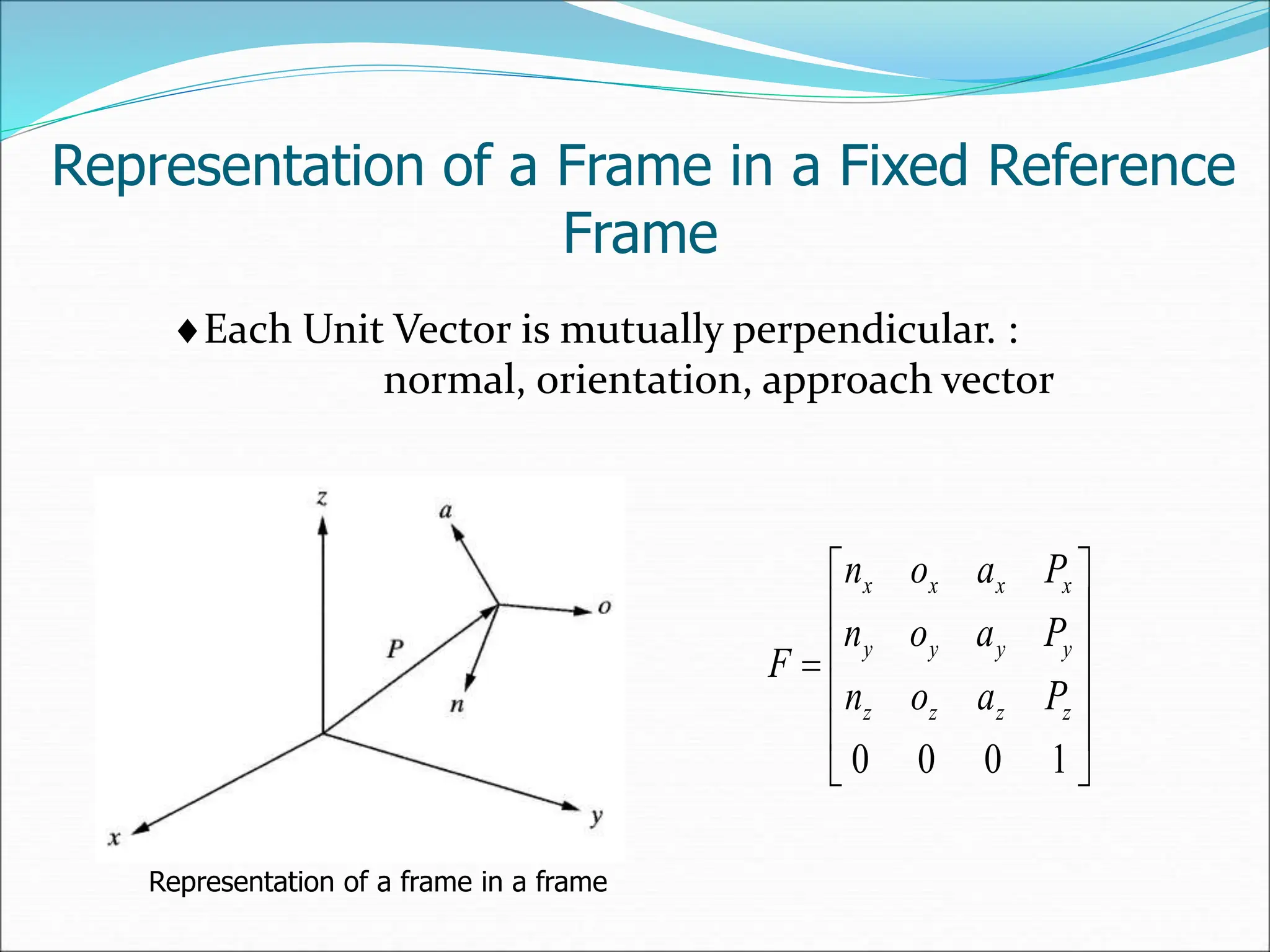
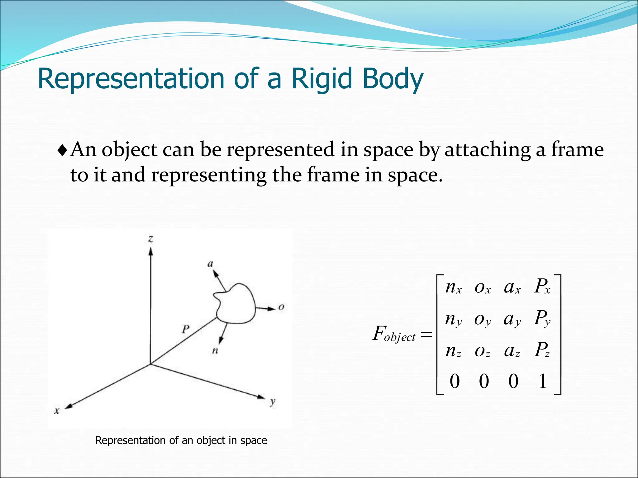
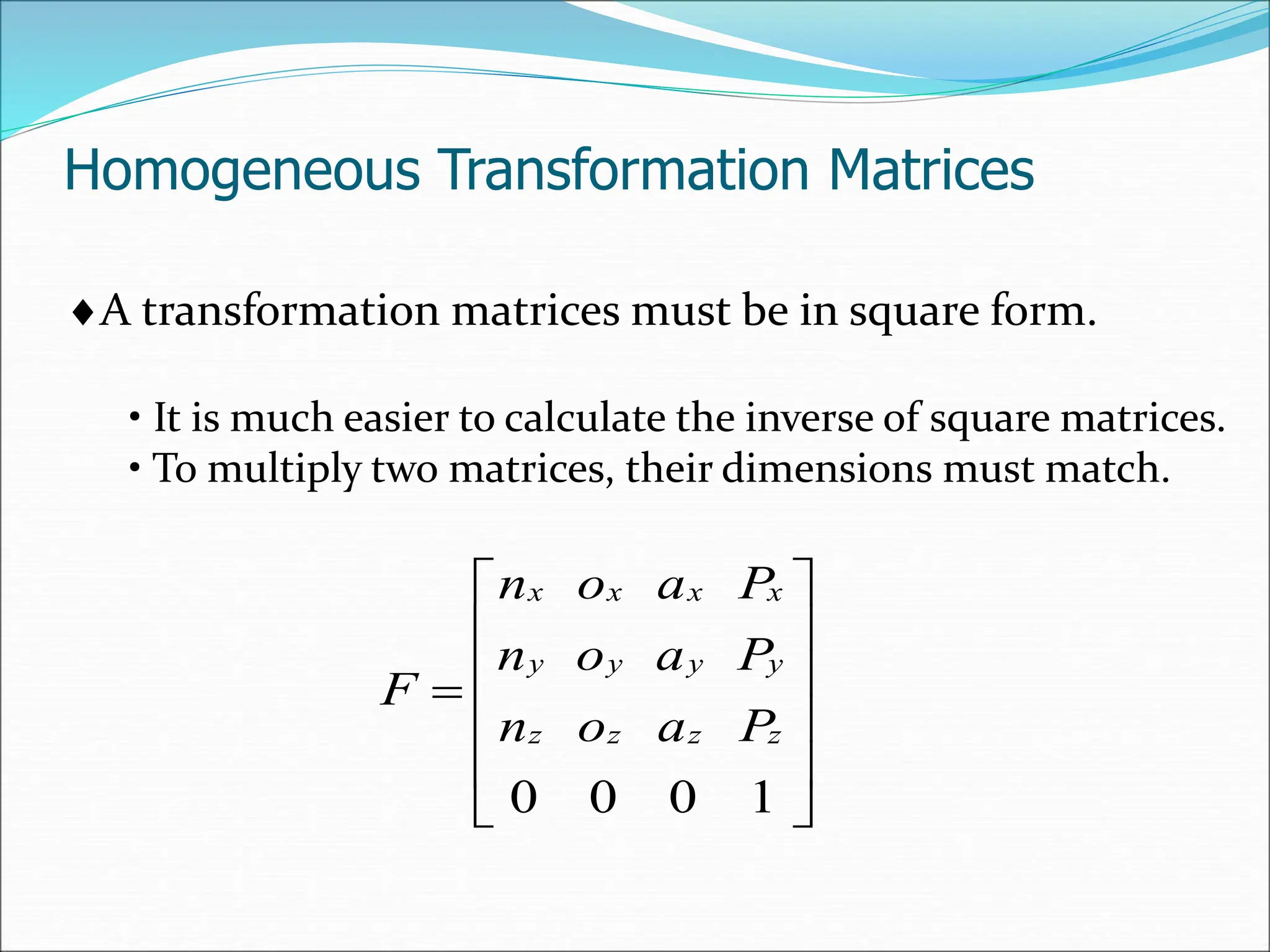
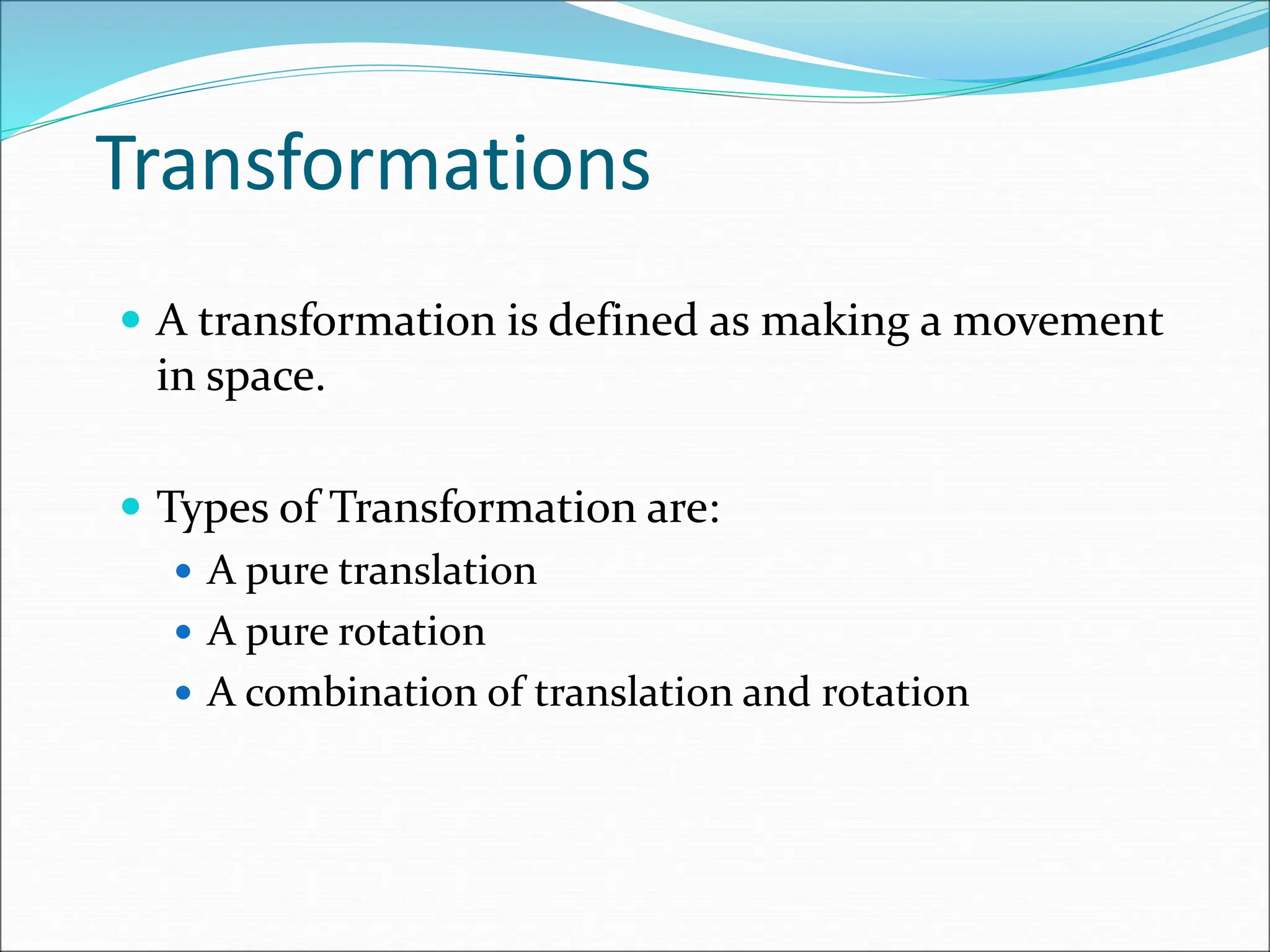
The document provides a detailed overview of robot kinematics, including forward and inverse kinematics for determining robot hand positions and joint variables. It covers matrix representations for points, vectors, and transformations in space, alongside numerical problems illustrating these concepts. Additionally, various robot coordinate systems, such as Cartesian, cylindrical, and spherical coordinates, are discussed for position analysis.

![Numerical Problem (Forward Kinematics)-2
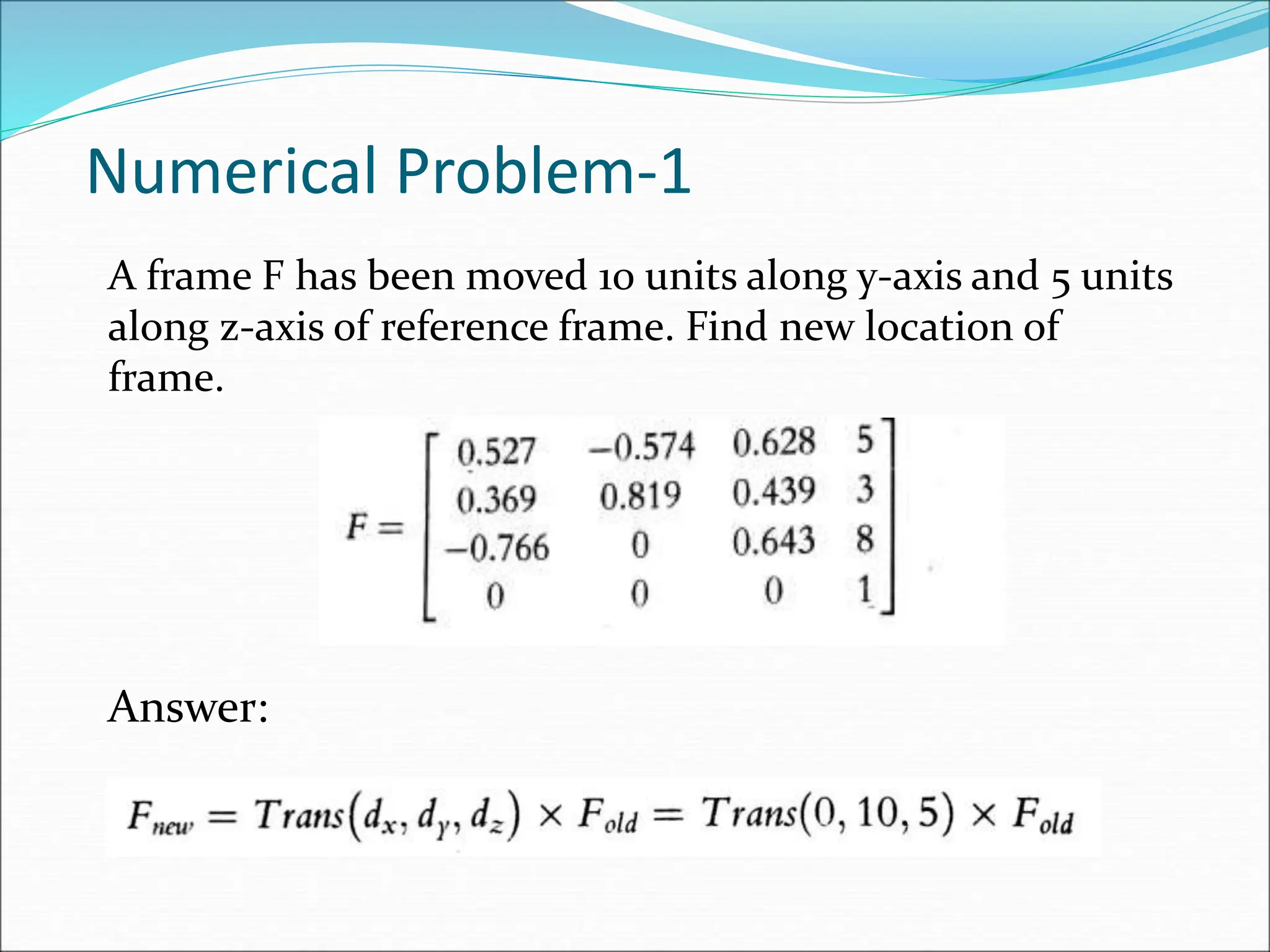
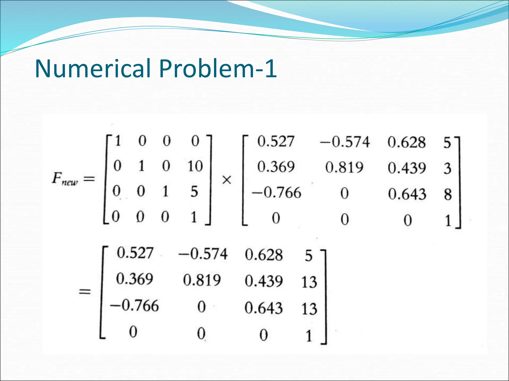
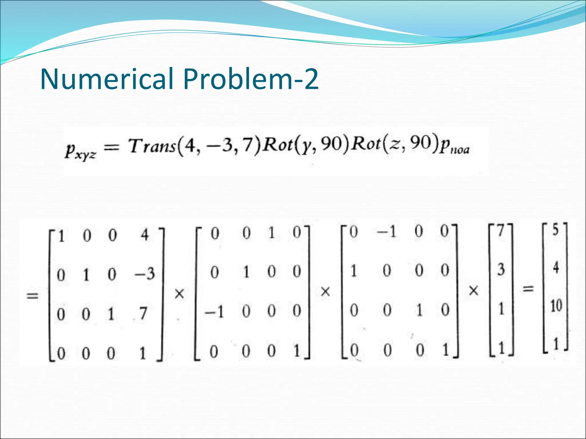
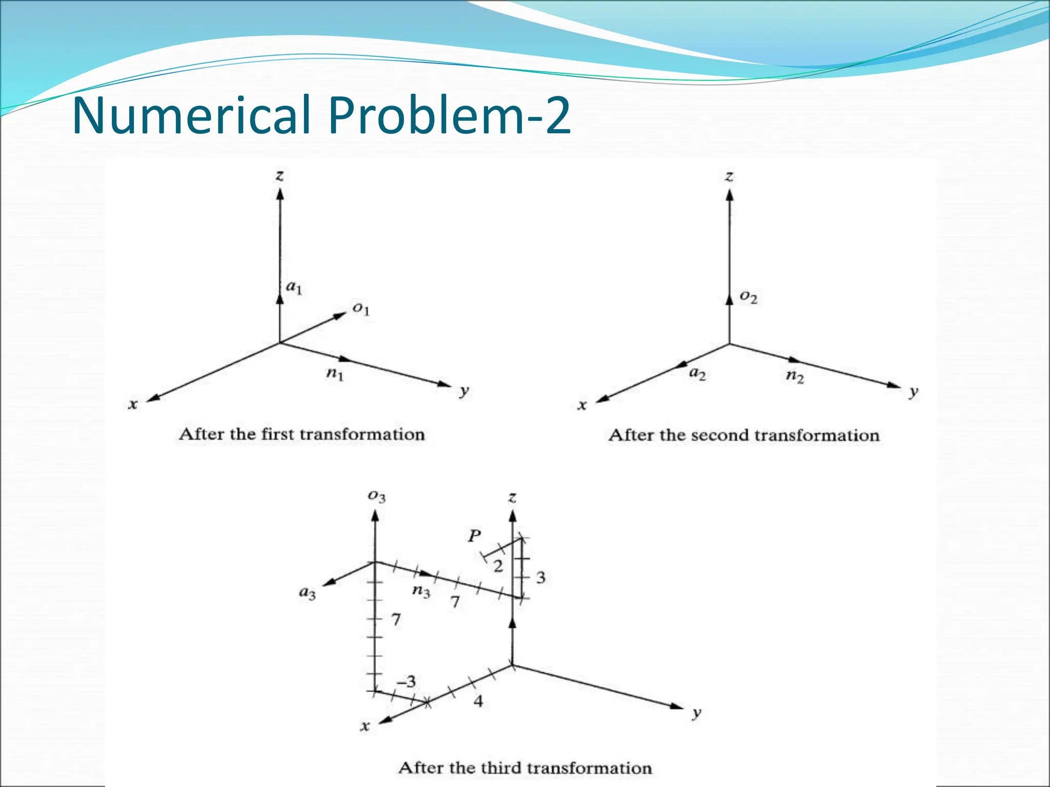
A point p(7,3,1) is attached to frame and subjected to
following transformations. Find coordinate of point
relative to reference frame.
1. Rotation of 90° about z-axis
2. Followed by rotation of 90 about y-axis
3. Followed by translation of [4,-3,7].
Answer: The matrix equation is given as](https://image.slidesharecdn.com/robotkinematics-160927173439-240701052708-00d37eb0/75/robotkinematics-16092vsdfva-sdaf7173439-ppt-17-2048.jpg)

![Suppose we desire to place the origin of hand frame of a
cylindrical robot at [ 3,4,7]. Calculate the joint variables of
robot.
Answer:
Numerical Problem (Inverse Kinematics)-3
1
0
0
0
1
0
0
0
0
l
rS
C
S
rC
S
C
T
T cyl
P
R
r= 5 units](https://image.slidesharecdn.com/robotkinematics-160927173439-240701052708-00d37eb0/75/robotkinematics-16092vsdfva-sdaf7173439-ppt-23-2048.jpg)