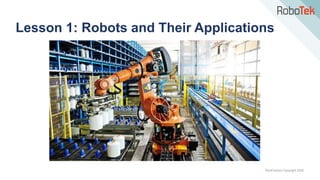
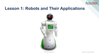
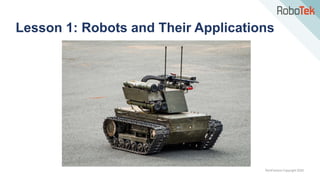
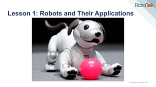
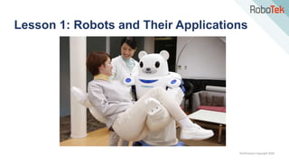
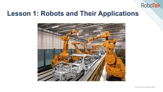
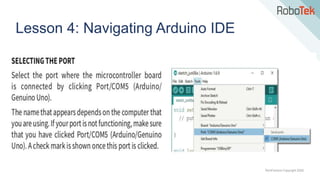
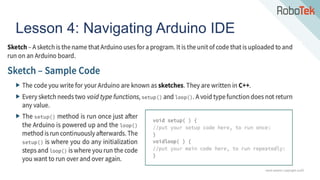
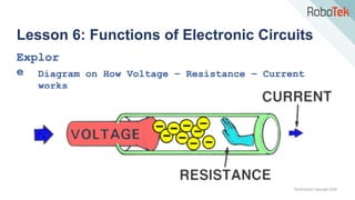
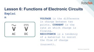
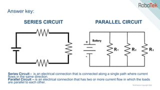
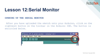
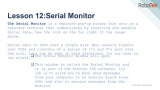
The document discusses the fundamentals of robotics, highlighting the various applications of robots in fields such as manufacturing, military, exploration, entertainment, and education. It explains the definition, characteristics, and classifications of robots, differentiating between industrial and service robots. Additionally, it covers the Arduino microcontroller, its components, and the Arduino IDE for programming, emphasizing the importance of microcontrollers in modern technology.


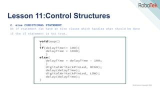


![TechFactors Copyright 2020
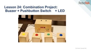
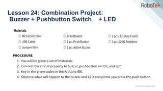
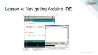
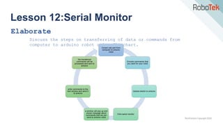
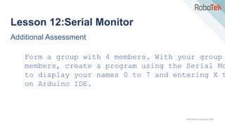
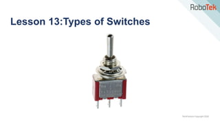
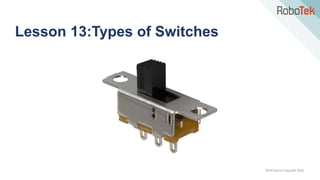
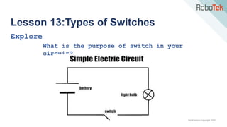
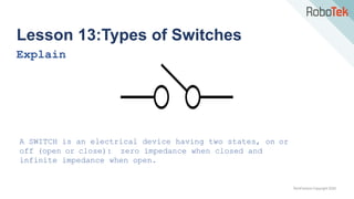
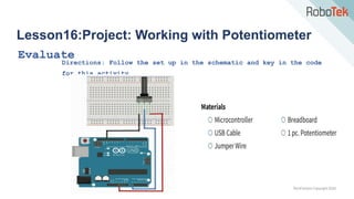
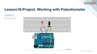
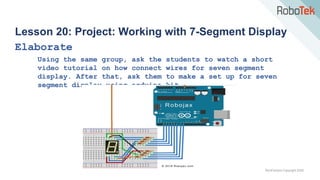
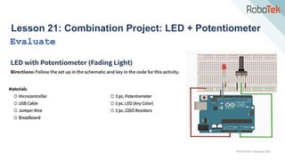
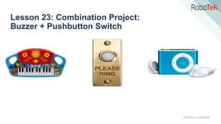
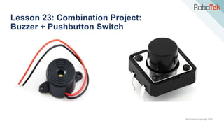
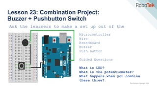
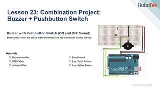
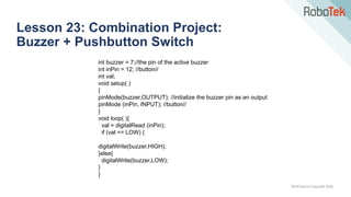
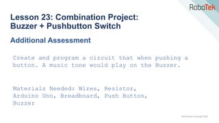
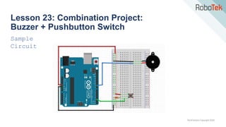
Lesson 23: Combination Project:
Buzzer + Pushbutton Switch
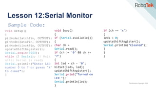
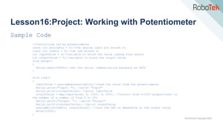
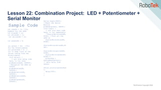
Sample Code
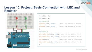
#include “pitches.h”
int melody[]={NOTE_C4, NOTE_G3, NOTE_G3, NOTE_A3, 0, NOTE_B3, NOTE_C4};
int buttonPin = 12;
Int noteDurations []={4,8,8,4,4,4,4,4};
void setup(){
pinMode(buttonPin, INPUT);}
void loop(){ //read the input pin
int buttonState = digitalRead(buttonPin); //if the button is pressed if
(buttonState == 1){ //iterate over the notes of the melody
for (int thisNote=0; thisNote <8; thisNote++){ //to calculate the note duration, take
one second. Divided by the note type
int noteDuration = 1000 / noteDurations [thisNote];
tone(8, melody [thisNote], noteDuration); //to distinguish the notes, set a minimum
time between them
//the note's duration +30% seems to work well
int pauseBetweenNotes = noteDuration * 1.30;
delay(pauseBetweenNotes); //stop the tone playing
noTone(8);
} }}](https://image.slidesharecdn.com/robotekarduinolevel1-240121173923-584b3fe7/85/RoboTek-Arduino-Level-1-pptx-411-320.jpg)