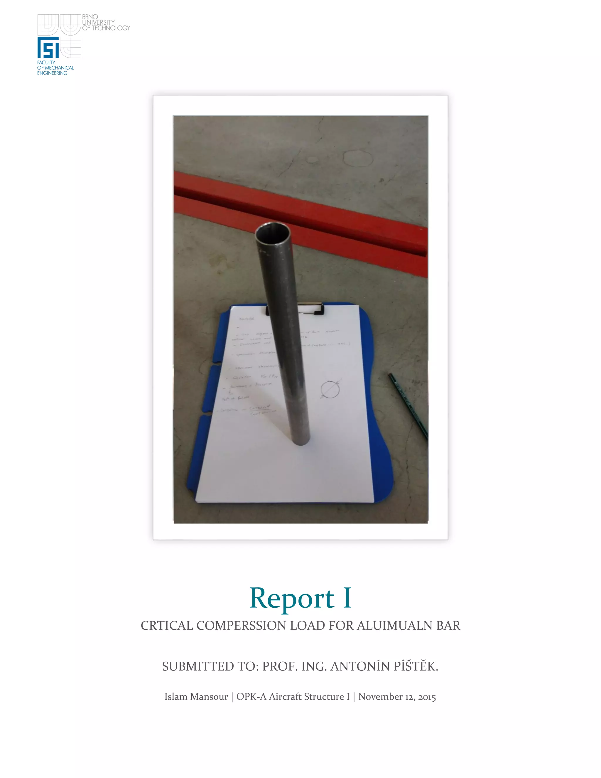
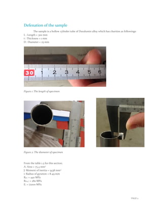
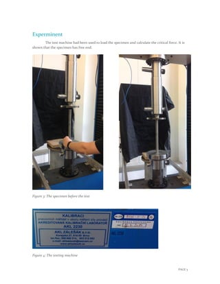
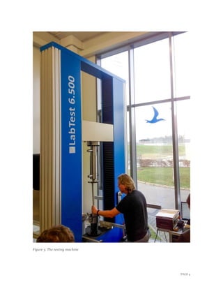
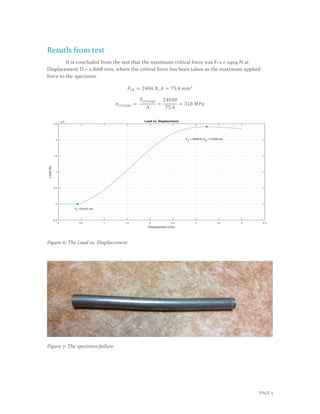
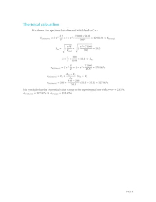
The document reports on an experiment to determine the critical compression load of an aluminum alloy bar. The bar was 300mm long with a 25mm diameter and 1mm thickness. It was tested on a machine that applied increasing loads until failure. The bar failed at a maximum load of 2404N. Calculations determined the theoretical critical load to be 42936N and theoretical critical stress to be 327MPa, which is close to the experimental value of 318MPa with a 2.83% error.
Episode 39 : Hopper Design
Problem:
1 -experiments with shear box jenike on a particulate catalyst to give the family
yield locus as in 1. given that the bulk density is 1000 kg/m3 particulates and wall friction angle is 15
a-from design chart silo cone, do design a mass flow hopper for the material.
b-if the average size is 100 um, calculate the discharge flow rate passing through the discharge opening
Β
2 - For the above materials using stainless steel is required to store 1000 tons of particulate in it. Coefficient of friction at the wall is given as 0.45 for each value and the formula that you use the appropriate justify the design.
a - draw the dimensions of the silo you and draw a vertical stress profile and the wall of the silo whole time say powerful particle
b- specify the maximum vertical stress and the wall of the silo you
c - if you use several different approaches in the design you provide appropriate recommendations to your employer for work before the end of the casting device fabrication started.
d - if problems such as the formation of the entrance are available after a certain time interval suggest measures - flow improvement measures to be taken to your employer
Β
SAJJAD KHUDHUR ABBAS
Ceo , Founder & Head of SHacademy
Chemical Engineering , Al-Muthanna University, Iraq
Oil & Gas Safety and Health Professional β OSHACADEMY
Trainer of Trainers (TOT) - Canadian Center of Human
Development
Robust model predictive control for discrete-time fractional-order systemsPantelis Sopasakis
Β
In this paper we propose a tube-based robust model predictive control scheme for fractional-order discrete-
time systems of the Grunwald-Letnikov type with state and input constraints. We first approximate the infinite-dimensional fractional-order system by a finite-dimensional linear system and we show that the actual dynamics can be approximated arbitrarily tight. We use the approximate dynamics to design a tube-based model predictive controller which endows to the controlled closed-loop system robust stability properties
We present a novel modeling
methodology to derive a nonlinear dynamical model which
adequately describes the effect of fuel sloshing on the attitude dynamics of a spacecraft. We model the impulsive thrusters using mixed logic and dynamics leading to a hybrid formulation.
We design a hybrid model predictive control scheme for the
attitude control of a launcher during its long coasting period,
aiming at minimising the actuation count of the thrusters.
Distributed solution of stochastic optimal control problem on GPUsPantelis Sopasakis
Β
Stochastic optimal control problems arise in many
applications and are, in principle,
large-scale involving up to millions of decision variables. Their
applicability in control applications is often limited by the
availability of algorithms that can solve them efficiently and within
the sampling time of the controlled system.
In this paper we propose a dual accelerated proximal
gradient algorithm which is amenable to parallelization and
demonstrate that its GPU implementation affords high speed-up
values (with respect to a CPU implementation) and greatly outperforms
well-established commercial optimizers such as Gurobi.
Time dispersion in time-of-arrival measurementsJohn Ashmead
Β
Can we prove that the Heisenberg uncertainty principle does not apply along the energy/time axis in the same way it applies along the space/momentum axis?
Talk given at the International Association for
Relativistic Dynamics
Real Time Code Generation for Nonlinear Model Predictive ControlBehzad Samadi
Β
This is a quick introduction to optimal control and nonlinear model predictive control. It also includes code generation for a NMPC controller. For a recorded webinar, follow this link: http://goo.gl/c5zFgN
Pressure Distribution on an Airfoil
The team conducted the experiment to determine the effects of pressure distribution on lift and pitching moment and the behavior of stall for laminar and turbulent boundary layers in the USNA Closed-Circuit Wing Tunnel (CCWT) with an NACA 65-012 airfoil at a Reynolds number of 1,000,000. The airfoil was tested in a clean configuration at angles of attack of 0, 5, 8, 10, and 12 degrees. Tape added to the leading edge tripped the boundary layer, and pressure distributions were taken at 8, 10, and 12 degrees angle of attack. Experimental results showed a suction peak at less than 1% of chord, providing a beneficial test article for contrast between smooth and laminar boundary layer behavior at the stall condition. The maximum lift coefficient for the clean airfoil was 0.9 at 10 degrees angle of attack, and tripped airfoil reached a maximum lift coefficient of 1.03 at 12 degrees angle of attack, a 14% increase. These data were 10% lower than the empirical airfoil data found in Theory of Wing Sections from Abbott and von Doenhoff. Pitching moment coefficient about the quarter chord remained near zero below stall as expected for a symmetrical airfoil, but rapidly became negative after stall for experimental and empirical data. The airfoil exhibited a leading edge stall for both laminar and turbulent boundary layers.
Test_description_for_dry-type-transformers_for_special_testsSARAVANAN A
Β
This technical article briefly describes seven very important tests you should perform during commissioning of a dry-type transformer. Usually, tests are performed in the factory where transformers are produced.
1. Islam Mansour | OPK-A Aircraft Structure I | November 12, 2015
Report I
CRTICAL COMPERSSION LOAD FOR ALUIMUALN BAR
SUBMITTED TO: PROF. ING. ANTONΓN PΓΕ TΔK.
2. PAGE 1
Contents
Defenation of the sample .............................................................................................................................2
Experminent ..................................................................................................................................................3
Resutls from test............................................................................................................................................5
Thertoical calcuatlion .................................................................................................................................. 6
Figure 1: The length of specimen .................................................................................................................2
Figure 2: The diameter of specimen ............................................................................................................2
Figure 3: The specimen before the test .......................................................................................................3
Figure 4: The testing machine......................................................................................................................3
Figure 5: The testing machine..................................................................................................................... 4
Figure 6: The Load vs. Displacement ..........................................................................................................5
Figure 7: The specimen failure.....................................................................................................................5
3. PAGE 2
Defenation of the sample
The sample is a hollow cylinder tube of Duralumin alloy which has charities as followings:
L : Length = 300 mm
t : Thickness = 1 mm
D : Diameter = 25 mm
Figure 1: The length of specimen
Figure 2: The diameter of specimen
From the table 1.5 for this section:
A: Area = 75.4 mm2
J: Moment of inertia = 5438 mm4
i: Radius of gyration = 8.49 mm
Rm: = 440 MPa
RP02: = 280 MPa
E: = 72000 MPa
4. PAGE 3
Experminent
The test machine had been used to load the specimen and calculate the critical force. It is
shown that the specimen has free end.
Figure 3: The specimen before the test
Figure 4: The testing machine
6. PAGE 5
Resutls from test
It is concluded from the test that the maximum critical force was FCR = 2404 N at
Displacement D = 2.8168 mm, where the critical force has been taken as the maximum applied
force to the specimen.
πΉπΆπ = 2404 π, π΄ = 75.4 ππ2
πππ(ππ₯π) =
πΉππ(ππ₯π)
π΄
=
24040
75.4
= 318 πππ
Figure 6: The Load vs. Displacement
Figure 7: The specimen failure
7. PAGE 6
Thertoical calcuatlion
It is shown that specimen has a free end which lead to C = 1
πΉπΆπ (π‘βπππ) = πΆ π2
πΈ π½
π2
= 1 β π2
β
72000 β 5438
3002
= 42936 π > πΉπΆπ (exp)
π π = βπ
π2 πΈ
π ππ2
= β1
π2 β 72000
280
= 50.3
π =
π
π
=
300
8.49
= 35.3 < π π
πππ(π‘βπππ) = πΆ π2
πΈ
π2
= 1 β π2
β
72000
35.52
= 570 πππ
πππ(π‘βπππ) = π π +
π π β π π
π π
(π π β π)
πππ(π‘βπππ) = 280 +
440 β 280
50.3
(50.3 β 35.3) = 327 πππ
It is conclude that the theoretical value is near to the experimental one with πππππ = 2.83 %
πππ(π‘βπππ) = 327 πππ β πππ(ππ₯π) = 318 πππ