Download to read offline
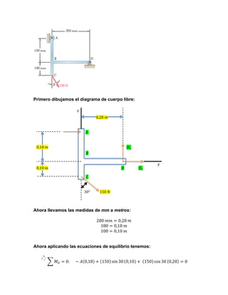


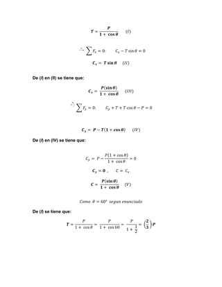

1) The document describes solving static equilibrium equations to analyze a lever system with forces applied. 2) Key values are calculated, such as the tension force TAB equals 300 N. 3) The normal and tangential force components Cx and Cy are calculated to be -380 N and -240 N, respectively.


