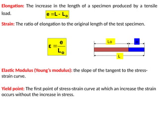
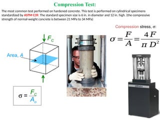
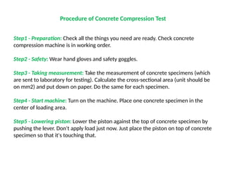
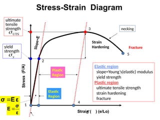
Compression, Flexural and Tensile
tests for concrete, steel and timber
Dr. Mohanad Talal Alfach
City, University of London
Learning Objectives:
After this lesson, students should be able to:
• Define engineering stress, engineering strain, Poisson’s ratio and modulus of
elasticity.
• Explain a typical engineering stress-strain diagram of an elastic material and its
important features.
• Determine elastic modulus, yield strength, and tensile strength from an
engineering stress-strain diagram.
• Understanding the reasons of material failure.
Engineering Connection:
When designing structures, engineers carefully choose the materials by
anticipating the forces the materials (the structural components) are expected
to experience during their lifetimes. The mechanical properties of these
materials are the most important properties because all service conditions and
most end-use applications in involve some degree of mechanical loading. The
material selection for a variety of applications is quite often based on
mechanical properties such as tensile strength, modulus, elongation and
impact strength. Usually, ductile materials such as steel and other metals are
used for components that experience tensile loads. Brittle materials such as
concrete are used for components that experience compressive loads.
Definitions:
Stress: is a ratio of applied load to the original cross-sectional area.
A
F F A
F
σ 
Elongation: The increase in the length of a specimen produced by a tensile
load.
Yield point: The first point of stress-strain curve at which an increase the strain
occurs without the increase in stress.
Strain: The ratio of elongation to the original length of the test specimen.
Lo e
L
o
L
e
ε 
o
L
L
e 

Elastic Modulus (Young’s modulus): the slope of the tangent to the stress-
strain curve.
Compression Test:
𝜎 =
𝐹
𝐴
=
4 𝐹
𝜋 𝐷2
The most common test performed on hardened concrete. This test is performed on cylindrical specimens
standardized by ASTM C39. The standard specimen size is 6 in. in diameter and 12 in. high. (the compressive
strength of normal-weight concrete is between 21 MPa to 34 MPa)
Compression stress, s:
Area, A
FC
s =
FC
Ao
Procedure of Concrete Compression Test
Step1 - Preparation: Check all the things you need are ready. Check concrete
compression machine is in working order.
Step2 - Safety: Wear hand gloves and safety goggles.
Step3 - Taking measurement: Take the measurement of concrete specimens (which
are sent to laboratory for testing). Calculate the cross-sectional area (unit should be
on mm2) and put down on paper. Do the same for each specimen.
Step4 - Start machine: Turn on the machine. Place one concrete specimen in the
center of loading area.
Step5 - Lowering piston: Lower the piston against the top of concrete specimen by
pushing the lever. Don't apply load just now. Just place the piston on top of concrete
specimen so that it's touching that.
Step6 - Applying load: Now the piston is on top of specimen. It is the
time to apply load. Pull the lever into holding position. Start the
compression test by Pressing the zero button on the display board.
Step7 - Increasing pressure: By turning pressure increasing valve
counter-clockwise, adjust the pressure on piston so that it matches
concrete compression strength value. Apply the load gradually without
shock.
Step8 - Test is complete: Observe the concrete specimen. When it
begins to break stop applying load.
Step9 - Recording: Record the ultimate load on paper displaying on
machine's display screen.
Step10 - Clean the machine: When the piston is back into its position,
clean the creaked concrete from the machine.
Step11 - Turning off machine: Match your record once again with the
result on display screen. The result should still be on display screen.
And then turn off the machine.
Step12 - Calculate concrete compressive strength: The result we got
from testing machine is the ultimate load to break the concrete
specimen. The load unit is generally in lb. We have to convert it in
newton (N). Our purpose is, to know the concrete compressive
strength.
Compressive strength =
• Shear stress, t:
Area, A Fs
Fs
t = Fs
Ao
• Tensile stress, s:
original area
before loading
Area, A
Ft
s =
Ft
Ao
Tensile Test
Ao Lo
L
P
P
 =
L/Lo
specimen
extensometer
A tensile test is a scientific test process involving the application of tension to a
specimen until it fractures. It is an important type of test for determining a
material’s tensile strength, yield strength and ductility.
Procedure of Tensile Test
- Before starting the test for tensile strength, use a Tensile Preparation ASTM E8 and mold the
sample material. Once the mold is whole, the sample will take on the shape of a slim dog
bone or dumbbell.
- Position the lower and upper clamps in their proper position to accommodate the length of
the test sample. Next, place the material between the tensile clamps. Vertically align the
sample from the upper clamp (the fixed grip) to the lower clamp (the grip in charge of
applying tension.
- After securing the sample, attach the extensometer to its length. While it undergoes testing,
the extensometer will be monitoring and measuring any changes in the material.
- To begin the tensile stress test, slowly separate the tensile clamps at a constant speed.
- During the test, the specimen will slowly elongate with the standardized speed. The data
gathering software will present the material’s test parameters, as well as the changes in the
gage length.
- While the substance undergoes tension, the elongation is occurring in the process. The
change in length brought about by the pulling forces is a measurement called “strain”.
- Eventually, the specimen will begin to deform in the middle of its length. Changes in the
stress-strain curve will begin to appear during this phase. Once the specimen breaks, the
tensile testing has officially ended.
- After the fracture, unlatch the specimen piece from the tensile clamps. The tensile testers
will calculate the tensile strength, yield strength and ductility of the material.
- The tensile strength will determine the material’s maximum tensile stress and Yield strength.
Tensile Strength : Comparison
Si crystal
<100>
Graphite/
Ceramics/
Semicond
Metals/
Alloys
Composites/
fibers
Polymers
Tensile
strength,
TS
(MPa)
PVC
Nylon 6,6
10
100
200
300
1000
Al (6061) a
Al (6061) ag
Cu (71500) hr
Ta (pure)
Ti (pure) a
Steel (1020)
Steel (4140) a
Steel (4140) qt
Ti (5Al-2.5Sn) a
W (pure)
Cu (71500) cw
LDPE
PP
PC PET
20
30
40
2000
3000
5000
Graphite
Al oxide
Concrete
Diamond
Glass-soda
Si nitride
HDPE
wood ( fiber)
wood(|| fiber)
1
GFRE(|| fiber)
GFRE( fiber)
CFRE(|| fiber)
CFRE( fiber)
AFRE(|| fiber)
AFRE( fiber)
E-glass fib
C fibers
Aramid fib
Flexural Strength Test
The procedures for conducting the flexural-strength test are as follows:
1. Assemble the loading device. Turn the test beam so that the finished
surface is to the side and centered in the loading assembly. Operate the
testing apparatus until the loading blocks are brought into contact with
the upper surface of the beam.
2. Apply the test load at a rate such that the increase in extreme
fiber stress in the beam is between 125 and 175 pounds
per square inch per minute. Obtain readings on the proving-ring dial and
convert them to corresponding total loads in pounds by applying the
proving-ring constant. Aside from the reading used to control the rate of
application of the load, the only reading necessary is the one that
corresponds to the maximum load applied to the beam.
3. After the specimen has broken, obtain dimensions of the cross section at
which failure occurred to the nearest 0.1 inch. These dimensions represent
the average width and average depth of the section in failure.
The flexural strength, expressed in terms of modulus of rupture, is
given in psi, and can be calculated as follows:
a. If the specimen broke within the middle third of the span length, use
the following equation:
Where:
R= modulus of rupture , MPa (psi)
P= maximum applied load, N (pounds)
L= span length, mm (in inches)
b= average width of specimen, mm (inches)
d= average depth of specimen, mm (inches)
Strain ( ) (e/Lo)
4
1
2
3
5
Str
ess
(F/
A)
Elastic
Region
Plastic
Region
Strain
Hardening Fracture
ultimate
tensile
strength
S
l
o
p
e
=
E
Elastic region
slope=Young’s(elastic) modulus
yield strength
Plastic region
ultimate tensile strength
strain hardening
fracture
necking
yield
strength
UTS

y

ε
E
σ 
ε
σ
E 

Stress-Strain Diagram
0.2
8
0.6
1
Magnesium,
Aluminum
Platinum
Silver, Gold
Tantalum
Zinc, Ti
Steel, Ni
Molybdenum
Graphite
Si crystal
Glass -soda
Concrete
Si nitride
Al oxide
PC
Wood( grain)
AFRE( fibers) *
CFRE*
GFRE*
Glass fibers only
Carbon fibers only
Aramid fibers only
Epoxy only
0.4
0.8
2
4
6
10
20
40
60
80
100
200
600
800
1000
1200
400
Tin
Cu alloys
Tungsten
<100>
<111>
Si carbide
Diamond
PTFE
HDPE
LDPE
PP
Polyester
PS
PET
CFRE( fibers) *
GFRE( fibers)*
GFRE(|| fibers)*
AFRE(|| fibers)*
CFRE(|| fibers)*
Young’s Moduli: Comparison
Metals
Alloys
Graphite
Ceramics
Semicond
Polymers
Composites
/fibers
E(GPa)
109
Pa
=
Questions?

Compression_Flexural_and_Tensile_tests.pptx

  • 1.
    Compression, Flexural andTensile tests for concrete, steel and timber Dr. Mohanad Talal Alfach City, University of London
  • 2.
    Learning Objectives: After thislesson, students should be able to: • Define engineering stress, engineering strain, Poisson’s ratio and modulus of elasticity. • Explain a typical engineering stress-strain diagram of an elastic material and its important features. • Determine elastic modulus, yield strength, and tensile strength from an engineering stress-strain diagram. • Understanding the reasons of material failure.
  • 3.
    Engineering Connection: When designingstructures, engineers carefully choose the materials by anticipating the forces the materials (the structural components) are expected to experience during their lifetimes. The mechanical properties of these materials are the most important properties because all service conditions and most end-use applications in involve some degree of mechanical loading. The material selection for a variety of applications is quite often based on mechanical properties such as tensile strength, modulus, elongation and impact strength. Usually, ductile materials such as steel and other metals are used for components that experience tensile loads. Brittle materials such as concrete are used for components that experience compressive loads. Definitions: Stress: is a ratio of applied load to the original cross-sectional area. A F F A F σ 
  • 4.
    Elongation: The increasein the length of a specimen produced by a tensile load. Yield point: The first point of stress-strain curve at which an increase the strain occurs without the increase in stress. Strain: The ratio of elongation to the original length of the test specimen. Lo e L o L e ε  o L L e   Elastic Modulus (Young’s modulus): the slope of the tangent to the stress- strain curve.
  • 5.
    Compression Test: 𝜎 = 𝐹 𝐴 = 4𝐹 𝜋 𝐷2 The most common test performed on hardened concrete. This test is performed on cylindrical specimens standardized by ASTM C39. The standard specimen size is 6 in. in diameter and 12 in. high. (the compressive strength of normal-weight concrete is between 21 MPa to 34 MPa) Compression stress, s: Area, A FC s = FC Ao
  • 6.
    Procedure of ConcreteCompression Test Step1 - Preparation: Check all the things you need are ready. Check concrete compression machine is in working order. Step2 - Safety: Wear hand gloves and safety goggles. Step3 - Taking measurement: Take the measurement of concrete specimens (which are sent to laboratory for testing). Calculate the cross-sectional area (unit should be on mm2) and put down on paper. Do the same for each specimen. Step4 - Start machine: Turn on the machine. Place one concrete specimen in the center of loading area. Step5 - Lowering piston: Lower the piston against the top of concrete specimen by pushing the lever. Don't apply load just now. Just place the piston on top of concrete specimen so that it's touching that.
  • 7.
    Step6 - Applyingload: Now the piston is on top of specimen. It is the time to apply load. Pull the lever into holding position. Start the compression test by Pressing the zero button on the display board. Step7 - Increasing pressure: By turning pressure increasing valve counter-clockwise, adjust the pressure on piston so that it matches concrete compression strength value. Apply the load gradually without shock. Step8 - Test is complete: Observe the concrete specimen. When it begins to break stop applying load. Step9 - Recording: Record the ultimate load on paper displaying on machine's display screen. Step10 - Clean the machine: When the piston is back into its position, clean the creaked concrete from the machine.
  • 8.
    Step11 - Turningoff machine: Match your record once again with the result on display screen. The result should still be on display screen. And then turn off the machine. Step12 - Calculate concrete compressive strength: The result we got from testing machine is the ultimate load to break the concrete specimen. The load unit is generally in lb. We have to convert it in newton (N). Our purpose is, to know the concrete compressive strength. Compressive strength =
  • 9.
    • Shear stress,t: Area, A Fs Fs t = Fs Ao • Tensile stress, s: original area before loading Area, A Ft s = Ft Ao
  • 10.
    Tensile Test Ao Lo L P P = L/Lo specimen extensometer A tensile test is a scientific test process involving the application of tension to a specimen until it fractures. It is an important type of test for determining a material’s tensile strength, yield strength and ductility.
  • 11.
    Procedure of TensileTest - Before starting the test for tensile strength, use a Tensile Preparation ASTM E8 and mold the sample material. Once the mold is whole, the sample will take on the shape of a slim dog bone or dumbbell. - Position the lower and upper clamps in their proper position to accommodate the length of the test sample. Next, place the material between the tensile clamps. Vertically align the sample from the upper clamp (the fixed grip) to the lower clamp (the grip in charge of applying tension. - After securing the sample, attach the extensometer to its length. While it undergoes testing, the extensometer will be monitoring and measuring any changes in the material. - To begin the tensile stress test, slowly separate the tensile clamps at a constant speed. - During the test, the specimen will slowly elongate with the standardized speed. The data gathering software will present the material’s test parameters, as well as the changes in the gage length. - While the substance undergoes tension, the elongation is occurring in the process. The change in length brought about by the pulling forces is a measurement called “strain”. - Eventually, the specimen will begin to deform in the middle of its length. Changes in the stress-strain curve will begin to appear during this phase. Once the specimen breaks, the tensile testing has officially ended. - After the fracture, unlatch the specimen piece from the tensile clamps. The tensile testers will calculate the tensile strength, yield strength and ductility of the material. - The tensile strength will determine the material’s maximum tensile stress and Yield strength.
  • 12.
    Tensile Strength :Comparison Si crystal <100> Graphite/ Ceramics/ Semicond Metals/ Alloys Composites/ fibers Polymers Tensile strength, TS (MPa) PVC Nylon 6,6 10 100 200 300 1000 Al (6061) a Al (6061) ag Cu (71500) hr Ta (pure) Ti (pure) a Steel (1020) Steel (4140) a Steel (4140) qt Ti (5Al-2.5Sn) a W (pure) Cu (71500) cw LDPE PP PC PET 20 30 40 2000 3000 5000 Graphite Al oxide Concrete Diamond Glass-soda Si nitride HDPE wood ( fiber) wood(|| fiber) 1 GFRE(|| fiber) GFRE( fiber) CFRE(|| fiber) CFRE( fiber) AFRE(|| fiber) AFRE( fiber) E-glass fib C fibers Aramid fib
  • 13.
  • 14.
    The procedures forconducting the flexural-strength test are as follows: 1. Assemble the loading device. Turn the test beam so that the finished surface is to the side and centered in the loading assembly. Operate the testing apparatus until the loading blocks are brought into contact with the upper surface of the beam. 2. Apply the test load at a rate such that the increase in extreme fiber stress in the beam is between 125 and 175 pounds per square inch per minute. Obtain readings on the proving-ring dial and convert them to corresponding total loads in pounds by applying the proving-ring constant. Aside from the reading used to control the rate of application of the load, the only reading necessary is the one that corresponds to the maximum load applied to the beam. 3. After the specimen has broken, obtain dimensions of the cross section at which failure occurred to the nearest 0.1 inch. These dimensions represent the average width and average depth of the section in failure.
  • 15.
    The flexural strength,expressed in terms of modulus of rupture, is given in psi, and can be calculated as follows: a. If the specimen broke within the middle third of the span length, use the following equation: Where: R= modulus of rupture , MPa (psi) P= maximum applied load, N (pounds) L= span length, mm (in inches) b= average width of specimen, mm (inches) d= average depth of specimen, mm (inches)
  • 16.
    Strain ( )(e/Lo) 4 1 2 3 5 Str ess (F/ A) Elastic Region Plastic Region Strain Hardening Fracture ultimate tensile strength S l o p e = E Elastic region slope=Young’s(elastic) modulus yield strength Plastic region ultimate tensile strength strain hardening fracture necking yield strength UTS  y  ε E σ  ε σ E   Stress-Strain Diagram
  • 17.
    0.2 8 0.6 1 Magnesium, Aluminum Platinum Silver, Gold Tantalum Zinc, Ti Steel,Ni Molybdenum Graphite Si crystal Glass -soda Concrete Si nitride Al oxide PC Wood( grain) AFRE( fibers) * CFRE* GFRE* Glass fibers only Carbon fibers only Aramid fibers only Epoxy only 0.4 0.8 2 4 6 10 20 40 60 80 100 200 600 800 1000 1200 400 Tin Cu alloys Tungsten <100> <111> Si carbide Diamond PTFE HDPE LDPE PP Polyester PS PET CFRE( fibers) * GFRE( fibers)* GFRE(|| fibers)* AFRE(|| fibers)* CFRE(|| fibers)* Young’s Moduli: Comparison Metals Alloys Graphite Ceramics Semicond Polymers Composites /fibers E(GPa) 109 Pa =
  • 18.