
Downloaded 15 times

![xxxii
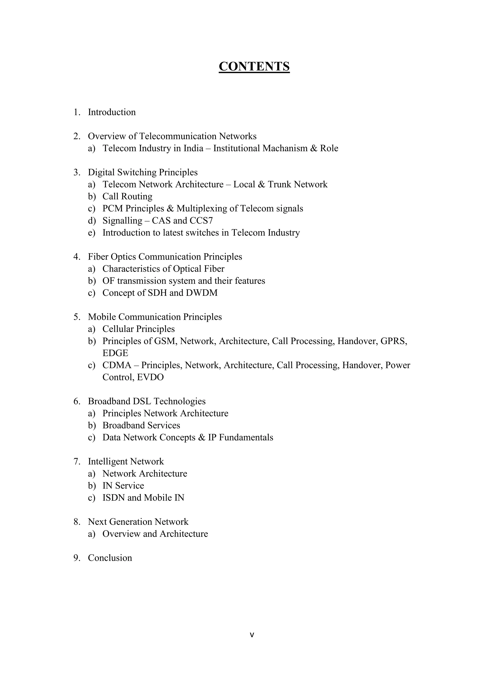
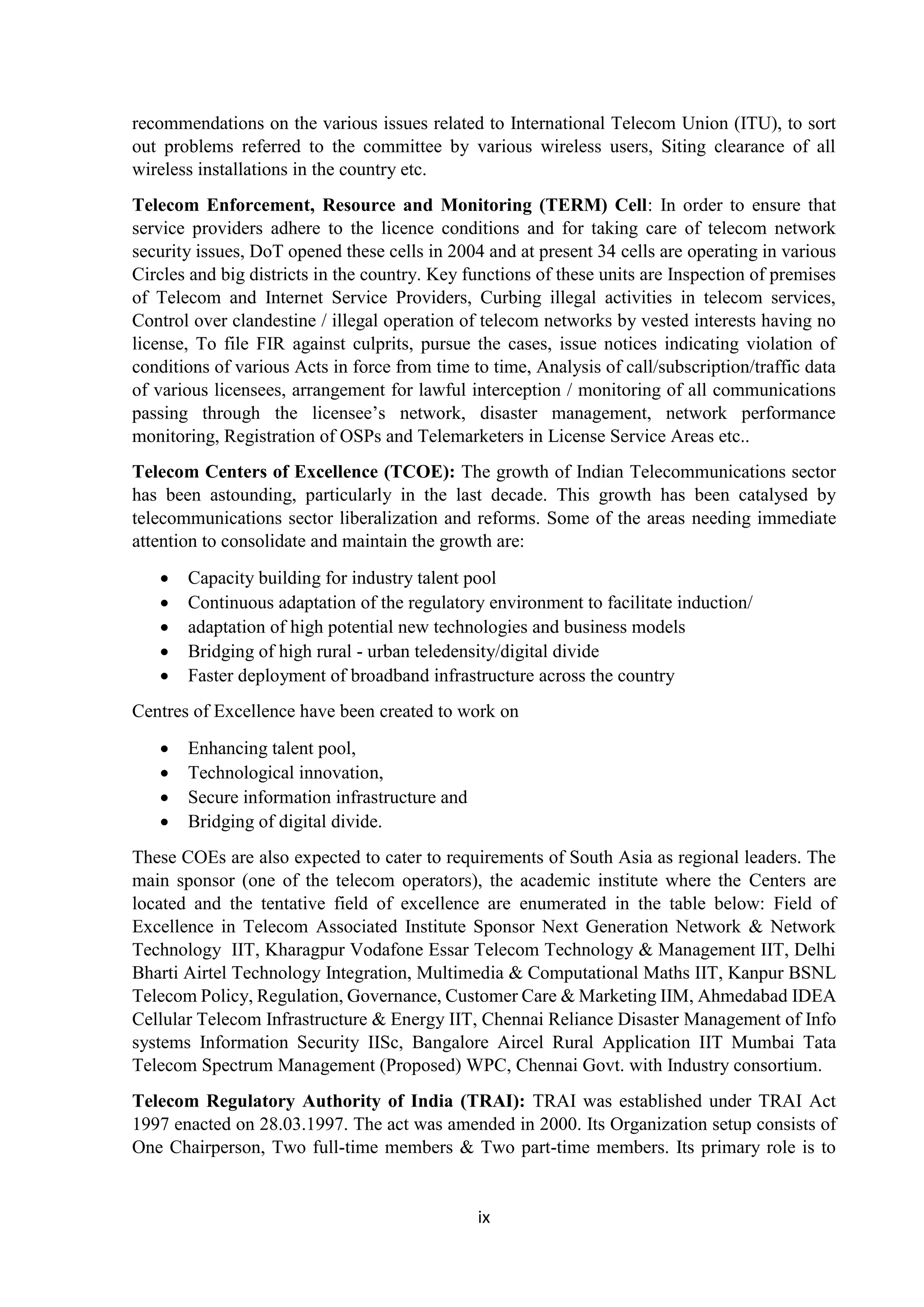
When joined together, these cells provide radio coverage over a wide geographic area. This
enables a large number of portable transceivers (e.g., mobile phones, tablets and laptops
equipped with mobile broadband modems, pagers, etc.) to communicate with each other and
with fixed transceivers and telephones anywhere in the network, via base stations, even if some
of the transceivers are moving through more than one cell during transmission.
Fig: Network structure
Cellular networks offer a number of desirable features:
More capacity than a single large transmitter, since the same frequency can be used for
multiple links as long as they are in different cells
Mobile devices use less power than with a single transmitter or satellite since the cell
towers are closer
Larger coverage area than a single terrestrial transmitter, since additional cell towers can
be added indefinitely and are not limited by the horizon
Major telecommunications providers have deployed voice and data cellular networks over most
of the inhabited land area of Earth. This allows mobile phones and mobile computing devices
to be connected to the public switched telephone network and public Internet. Private cellular
networks can be used for research[2]
or for large organizations and fleets, such as dispatch for
local public safety agencies or a taxicab company.
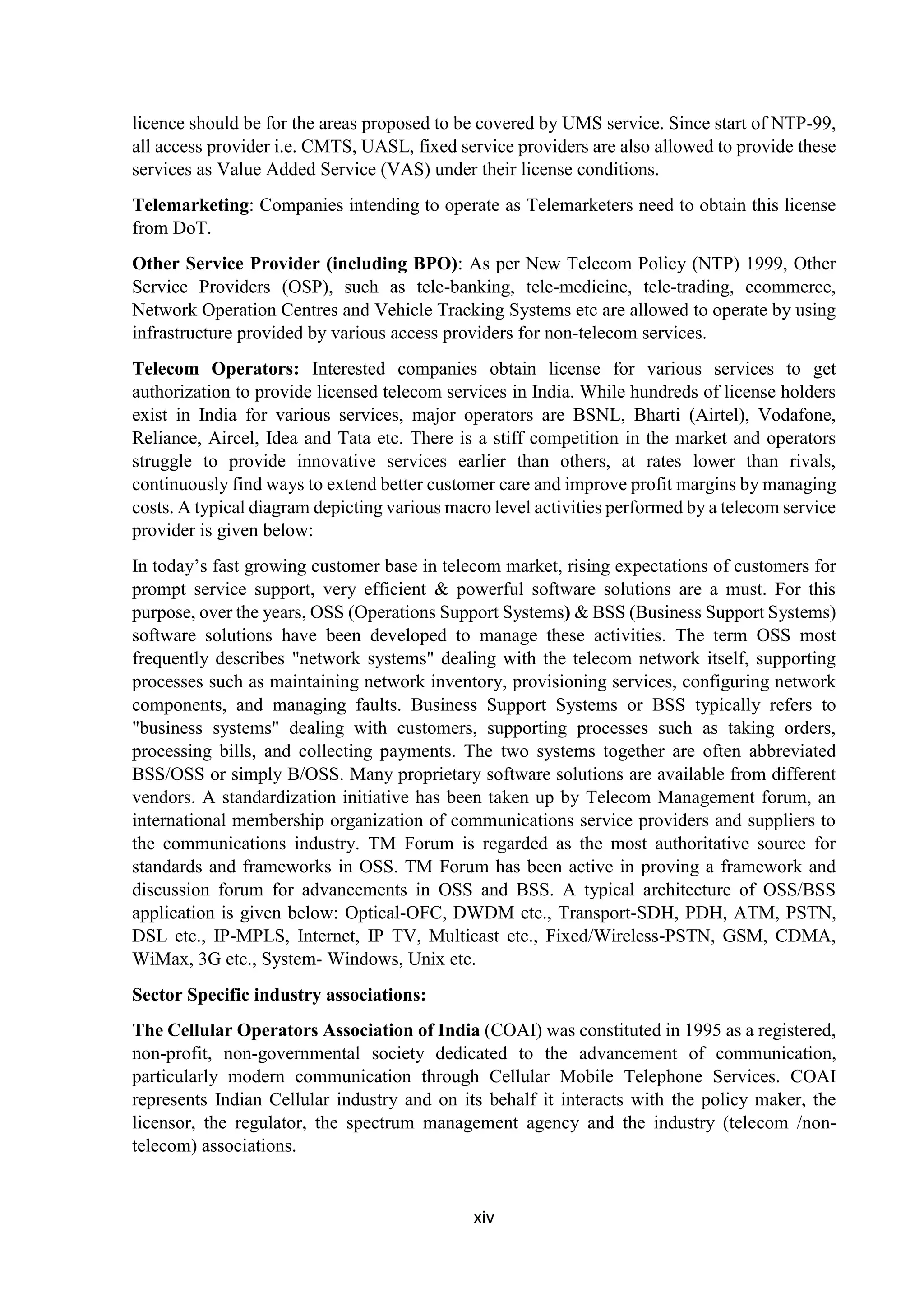
Concept: In a cellular radio system, a land area to be supplied with radio service is divided into
cells, in a pattern which depends on terrain and reception characteristics but which can consist
of roughly hexagonal, square, circular or some other regular shapes, although hexagonal cells
are conventional. Each of these cells is assigned with multiple frequencies (f1– f6) which have
corresponding radio base stations. The group of frequencies can be reused in other cells,
provided that the same frequencies are not reused in adjacent neighbouring cells as that would
cause interference. The increased capacity in a cellular network, compared with a network with
a single transmitter, comes from the mobile communication switching system developed
by Amos Joel of Bell Labs[4]
that permitted multiple callers in the same area to use the same
frequency by switching calls made using the same frequency to the nearest available cellular](https://image.slidesharecdn.com/bsnlfinalreportnandu1-181031152521/75/REPORT-ON-ADVANCED-TELECOM-32-2048.jpg)
![xxxiii
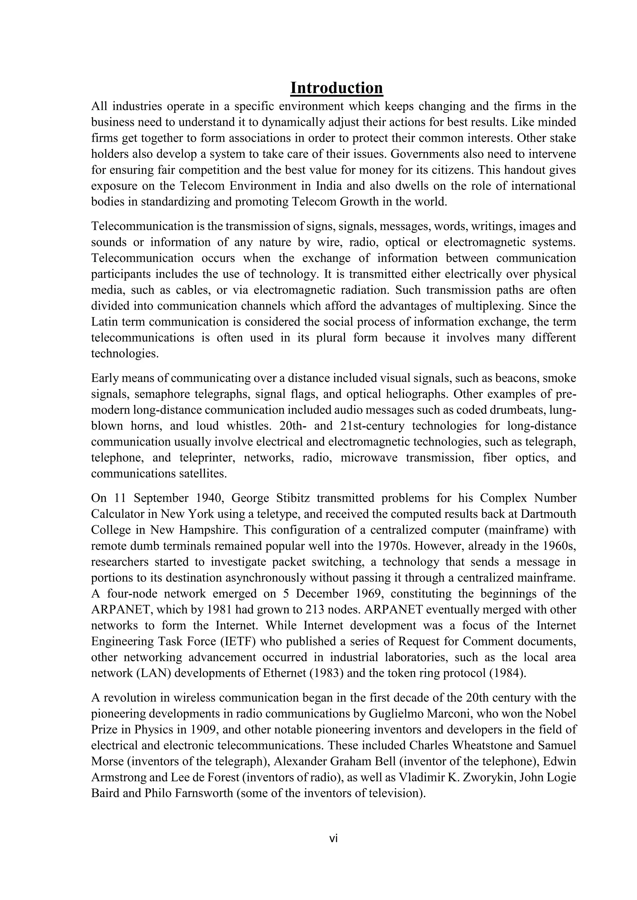
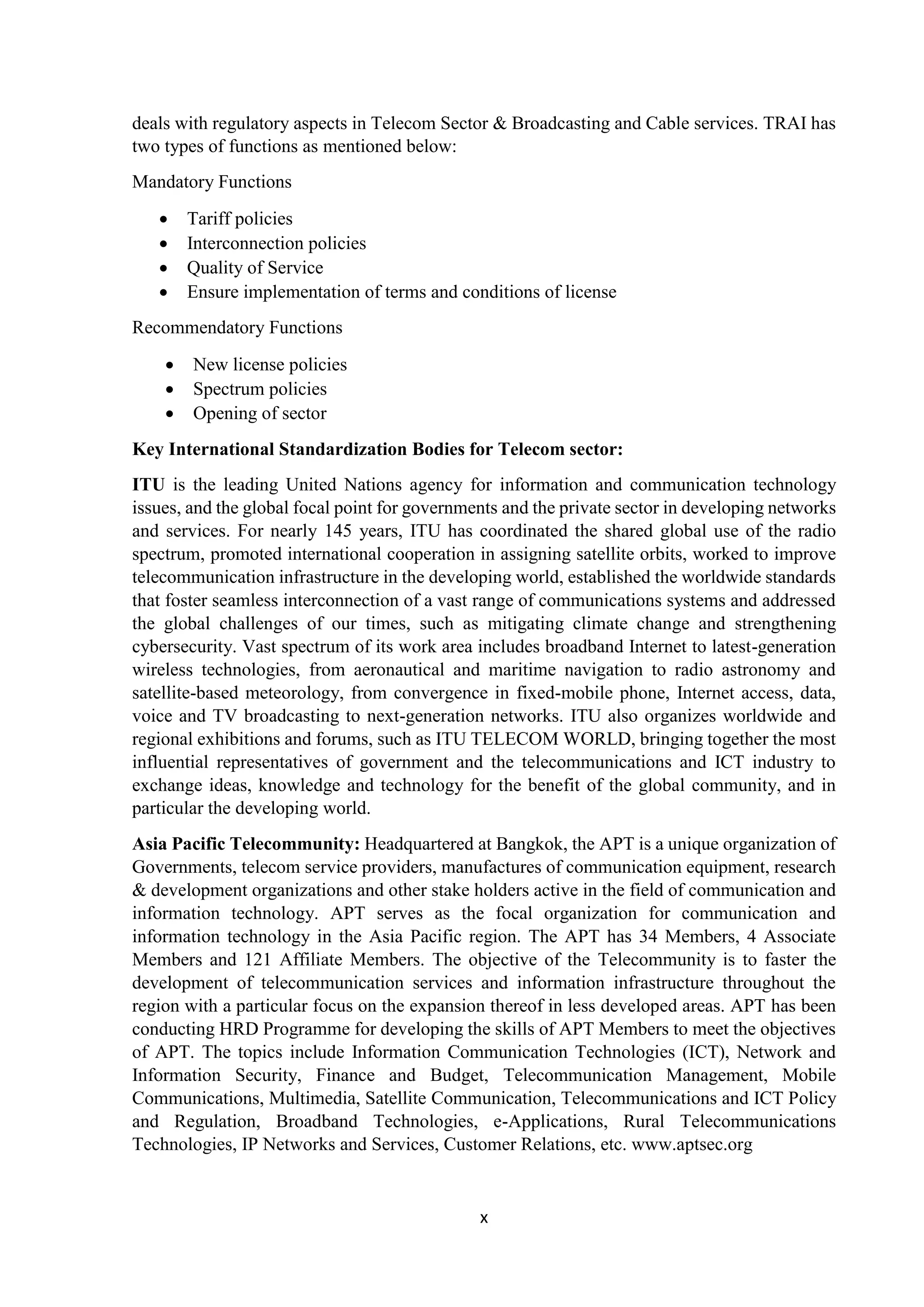
tower having that frequency available and from the fact that the same radio frequency can be
reused in a different area for a completely different transmission. If there is a single plain
transmitter, only one transmission can be used on any given frequency.
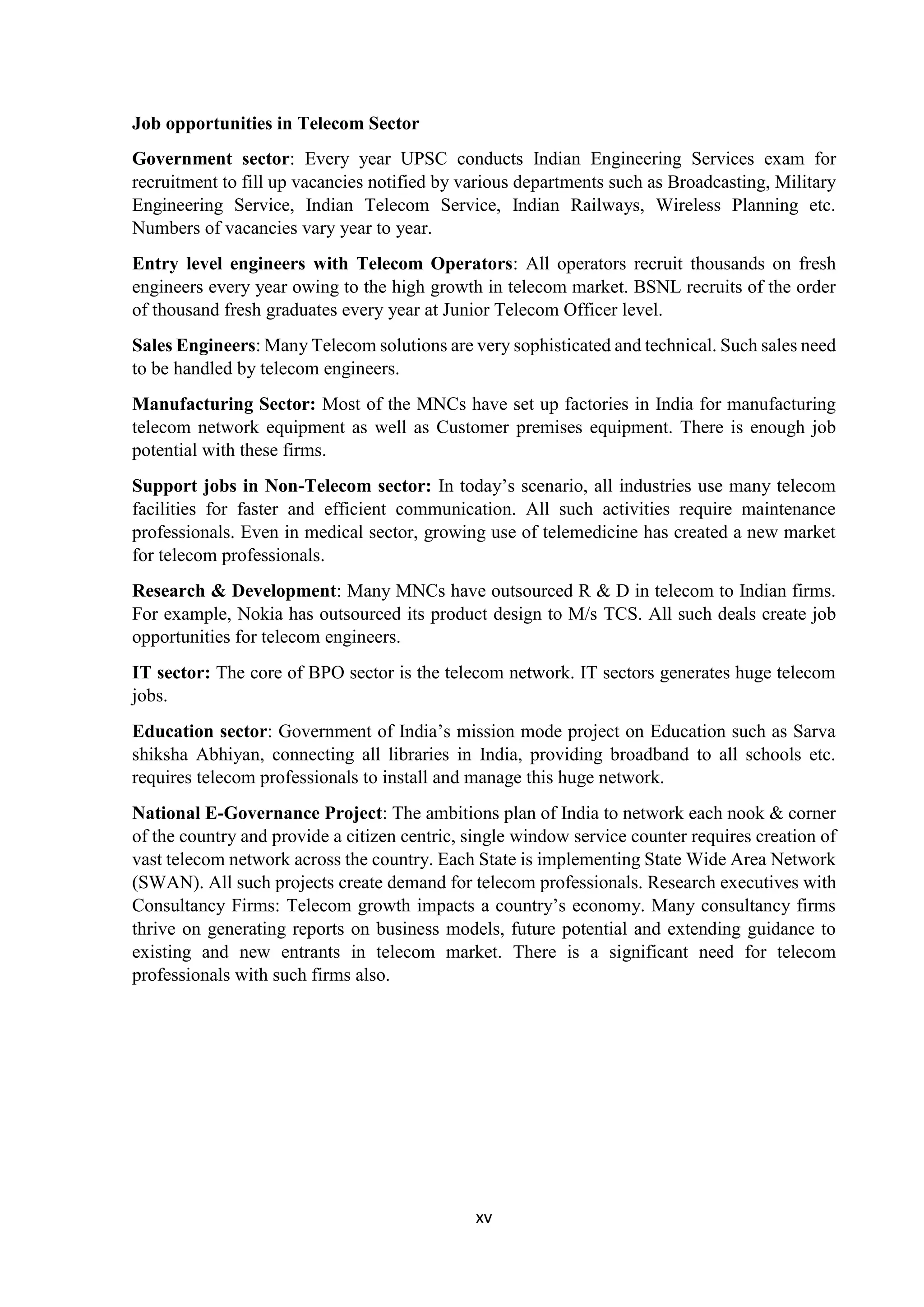
Fig: Frequency reuse
Cell towers frequently use a directional signal to improve reception in higher-traffic areas. In
the United States, the FCC limits omnidirectional cell tower signals to 100 watts of power. If
the tower has directional antennas, the FCC allows the cell operator to broadcast up to 500 watts
of effective radiated power (ERP).
Although the original cell towers created an even, omnidirectional signal, were at the centers
of the cells and were omnidirectional, a cellular map can be redrawn with the cellular telephone
towers located at the corners of the hexagons where three cells converge.[9]
Each tower has
three sets of directional antennas aimed in three different directions with 120 degrees for each
cell (totaling 360 degrees) and receiving/transmitting into three different cells at different
frequencies.
The numbers in the illustration are channel numbers, which repeat every 3 cells. Large cells can
be subdivided into smaller cells for high volume areas.
Fig: Cellular telephone frequency reuse pattern](https://image.slidesharecdn.com/bsnlfinalreportnandu1-181031152521/75/REPORT-ON-ADVANCED-TELECOM-33-2048.jpg)
![xxxvi
GPRS is a best-effort service, implying variable throughput and latency that depend on the
number of other users sharing the service concurrently, as opposed to circuit switching, where
a certain quality of service (QoS) is guaranteed during the connection. In 2G systems, GPRS
provides data rates of 56–114 kbit/sec. 2G cellular technology combined with GPRS is
sometimes described as 2.5G, that is, a technology between the second (2G) and third (3G)
generations of mobile telephony.[4] It provides moderate-speed data transfer, by using unused
time division multiple access (TDMA) channels in, for example, the GSM system. GPRS is
integrated into GSM Release 97 and newer releases.
EDGE: It is a data system used on top of GSM networks. It provides nearly three times faster
speeds than the outdated GPRS system. The theoretical maximum speed is 473 kbps for 8
timeslots but it is typically limited to 135 kbps in order to conserve spectrum resources. Both
phone and network must support EDGE, otherwise the phone will revert automatically to
GPRS.
EDGE meets the requirements for a 3G network but is usually classified as 2.75G.
Enhanced Data rates for GSM Evolution (EDGE) (also known as Enhanced GPRS (EGPRS),
or IMT Single Carrier (IMT-SC), or Enhanced Data rates for Global Evolution) is a
digital mobile phone technology that allows improved data transmission rates as a backward-
compatible extension of GSM. EDGE is considered a pre-3G radio technology and is part
of ITU's 3G definition.[1]
EDGE was deployed on GSM networks beginning in 2003 – initially
by Cingular(now AT&T) in the United States.
EDGE is standardized also by 3GPP as part of the GSM family. A variant, so called Compact-
EDGE, was developed for use in a portion of Digital AMPSnetwork spectrum.
Through the introduction of sophisticated methods of coding and transmitting data, EDGE
delivers higher bit-rates per radio channel, resulting in a threefold increase in capacity and
performance compared with an ordinary GSM/GPRS connection.
EDGE can be used for any packet switched application, such as an Internet connection.
Evolved EDGE continues in Release 7 of the 3GPP standard providing reduced latency and
more than doubled performance e.g. to complement High-Speed Packet Access (HSPA). Peak
bit-rates of up to 1 Mbit/s and typical bit-rates of 400 kbit/s can be expected.
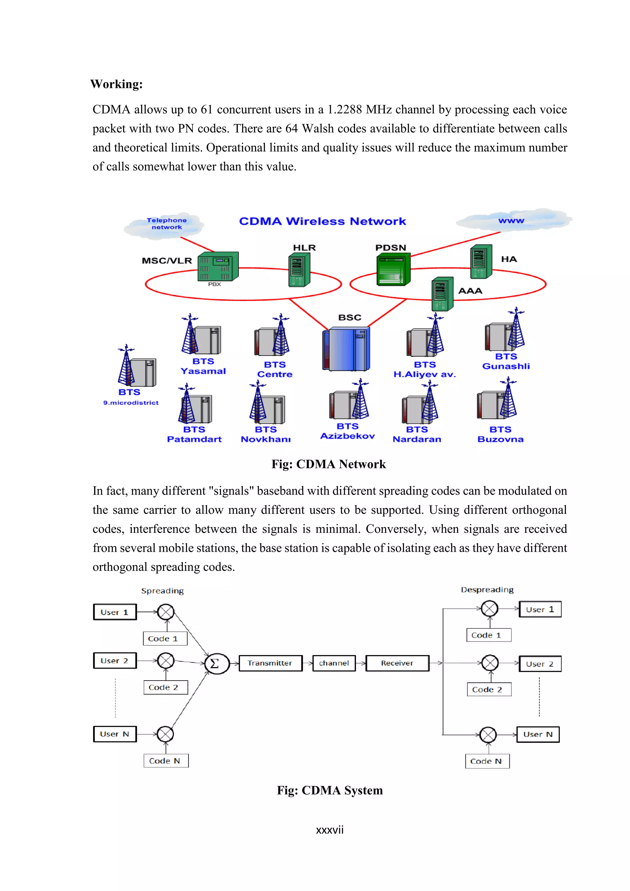
CDMA: Code-division multiple access (CDMA) is a channel access method used by
various radio communication technologies.
CDMA is an example of multiple access, where several transmitters can send information
simultaneously over a single communication channel. This allows several users to share a band
of frequencies (see bandwidth). To permit this without undue interference between the users,
CDMA employs spread spectrum technology and a special coding scheme (where each
transmitter is assigned a code).
CDMA is used as the access method in many mobile phone standards. IS-95, also called
"cdmaOne", and its 3G evolution CDMA2000, are often simply referred to as "CDMA",
but UMTS, the 3G standard used by GSM carriers, also uses "wideband CDMA", or W-
CDMA, as well as TD-CDMA and TD-SCDMA, as its radio technologies.](https://image.slidesharecdn.com/bsnlfinalreportnandu1-181031152521/75/REPORT-ON-ADVANCED-TELECOM-36-2048.jpg)
![xxxviii
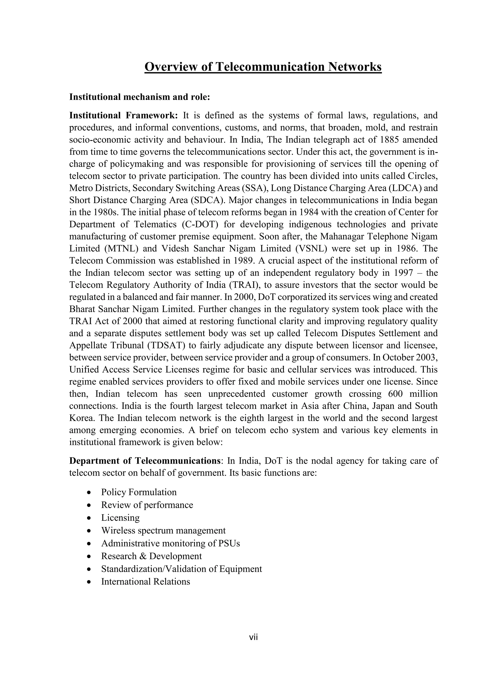
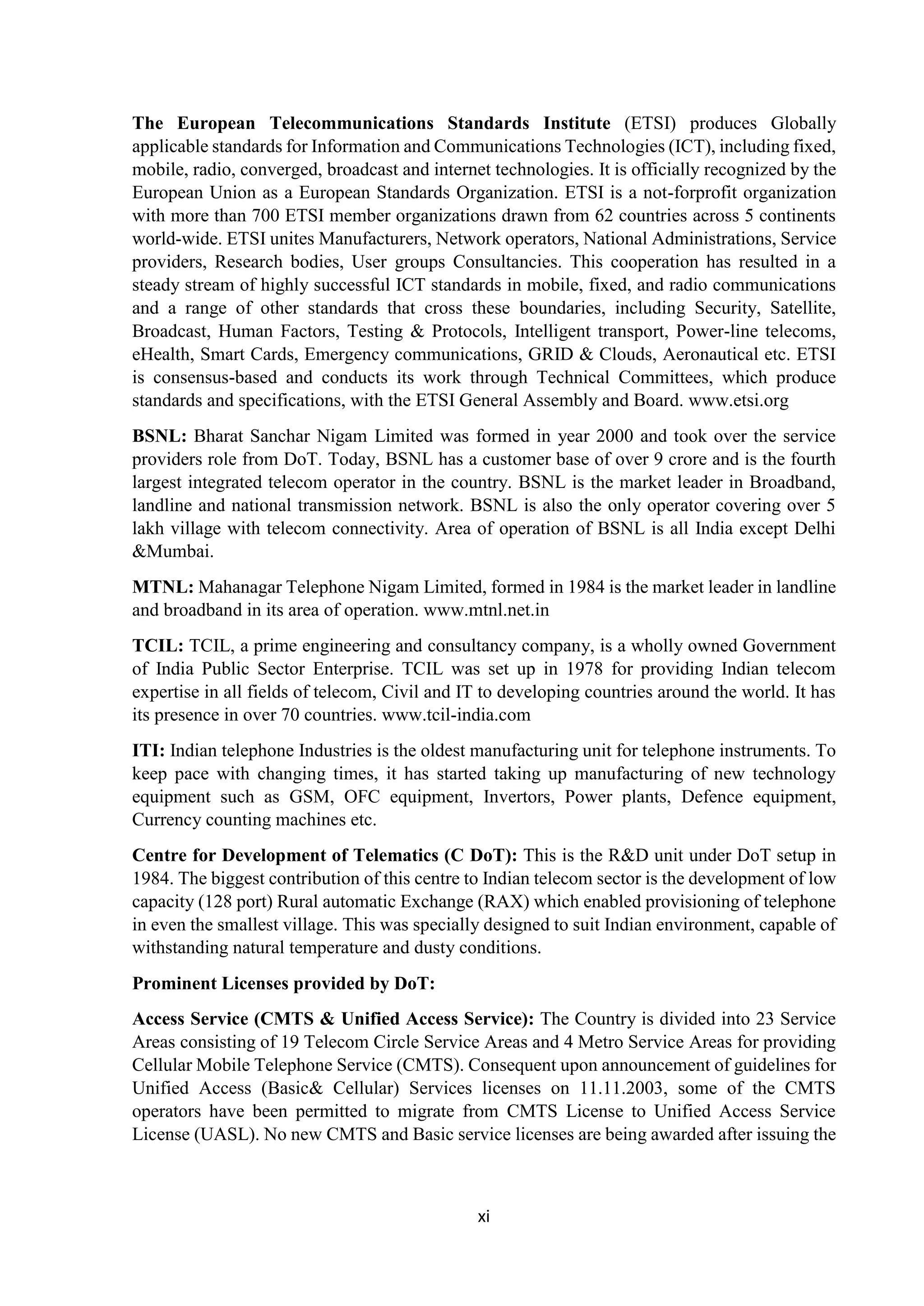
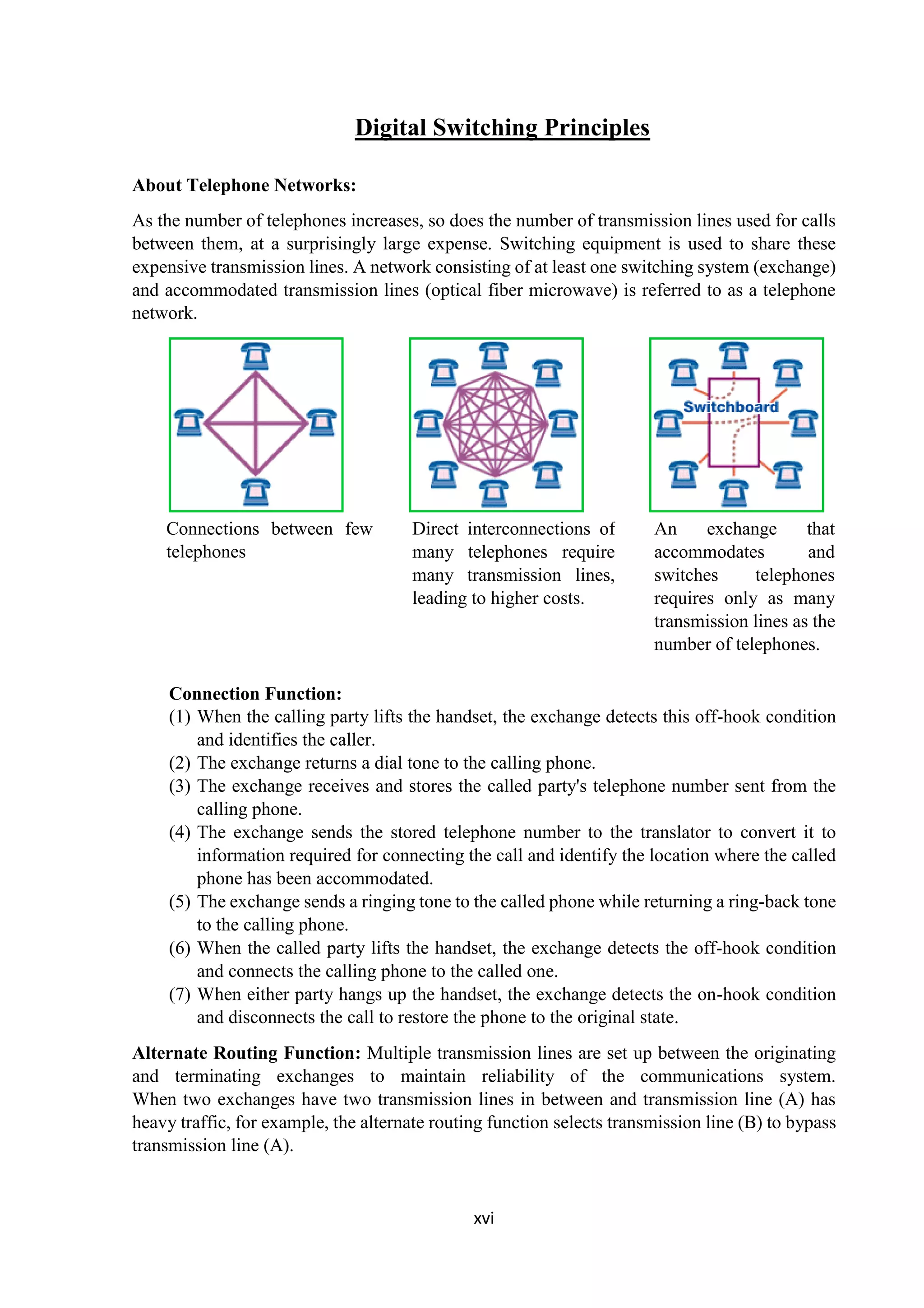
The following figure shows the technicality of the CDMA system. During the propagation, we
mixed the signals of all users, but by that you use the same code as the code that was used at
the time of sending the receiving side. You can take out only the signal of each user.
Processing gain:
CDMA is a spread spectrum technique. Each data bit is spread by a code sequence. This means,
energy per bit is also increased. This means that we get a gain of this.
P (gain) = 10log (W/R)
W is Spread Rate
R is Data Rate
For CDMA P (gain) = 10 log (1228800/9600) = 21dB
This is a gain factor and the actual data propagation rate. On an average, a typical transmission
condition requires a signal to the noise ratio of 7 dB for the adequate quality of voice.
Translated into a ratio, signal must be five times stronger than noise.
Actual processing gain = P (gain) – SNR
= 21 – 7 = 14dB
CDMA uses variable rate coder
The Voice Activity Factor of 0.4 is considered = -4dB.
Hence, CDMA has 100% frequency reuse. Use of same frequency in surrounding cells causes
some additional interference.
In CDMA frequency, reuse efficiency is 0.67 (70% eff.) = -1.73dB
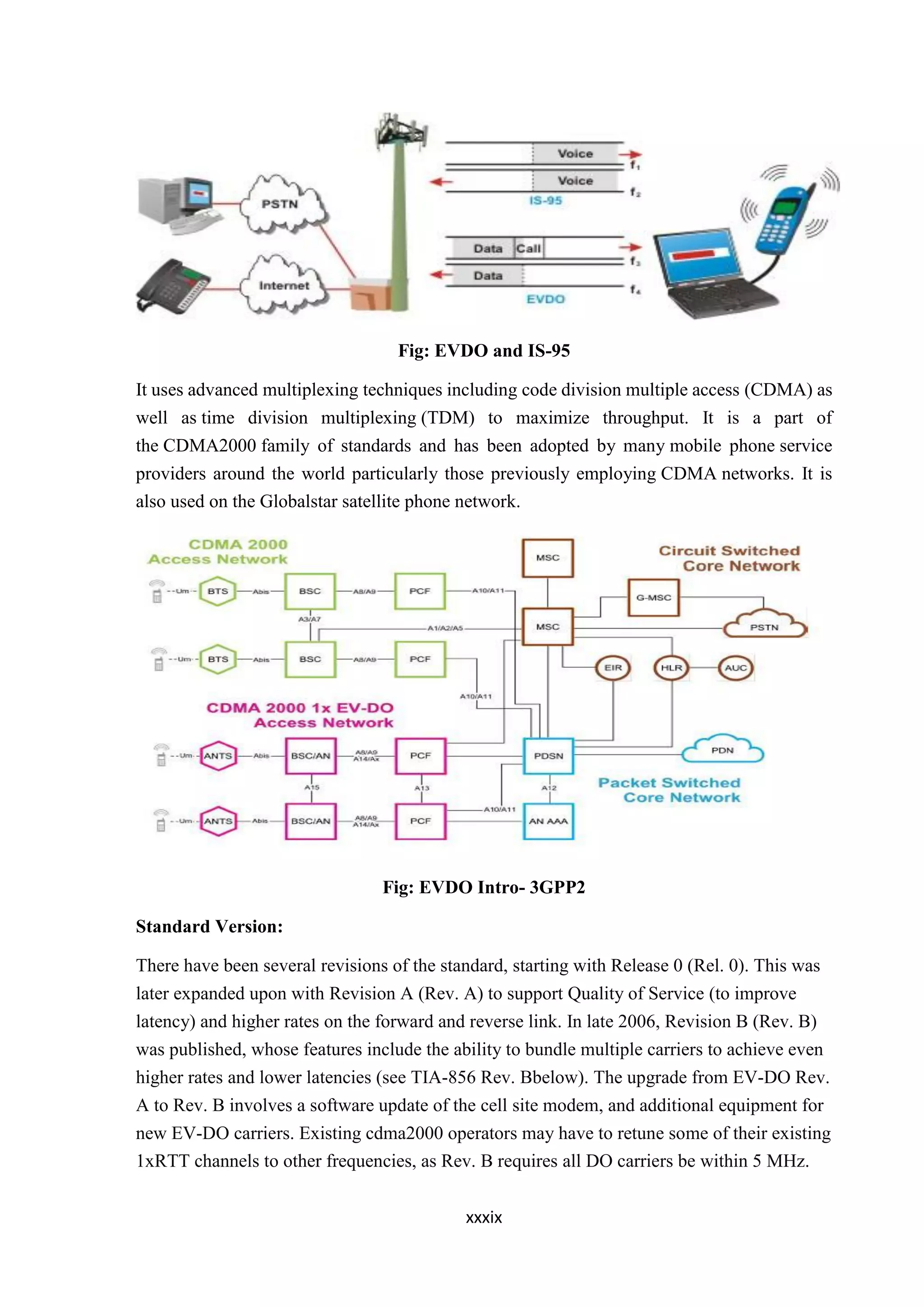
Evolution-Data Optimized (EV-DO, EVDO):
It is a telecommunications standard for the wireless transmission of data through radio signals,
typically for broadband Internet access. EV-DO is an evolution of the CDMA2000 (IS-2000)
standard which supports high data rates and can be deployed alongside a wireless carrier's
voice services.
An EV-DO channel has a bandwidth of 1.25 MHz, the same bandwidth size that IS-95A (IS-
95) and IS-2000 (1xRTT) use,[3]
though the channel structure is very different. The back-end
network is entirely packet-based, and is not constrained by restrictions typically present on
a circuit switched network.](https://image.slidesharecdn.com/bsnlfinalreportnandu1-181031152521/75/REPORT-ON-ADVANCED-TELECOM-38-2048.jpg)
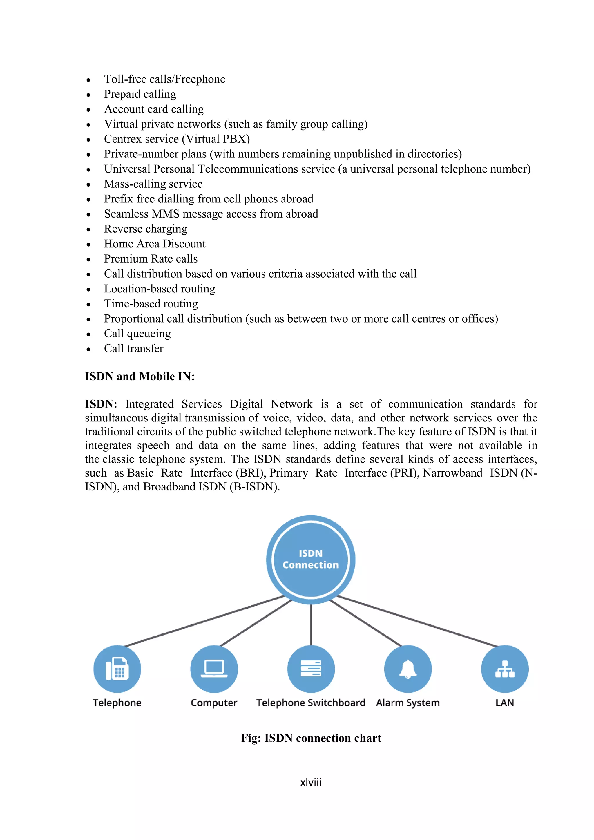
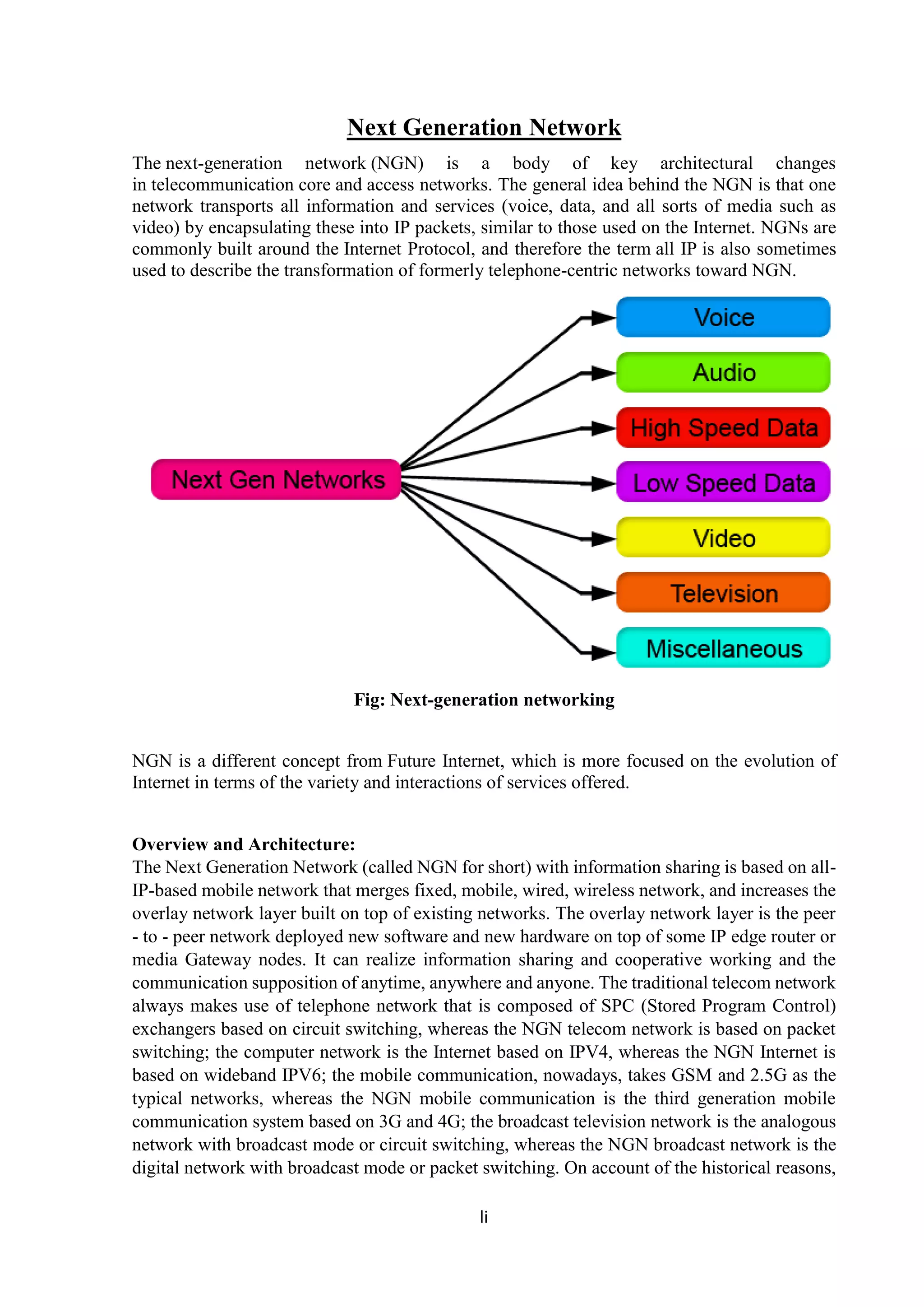
![lii
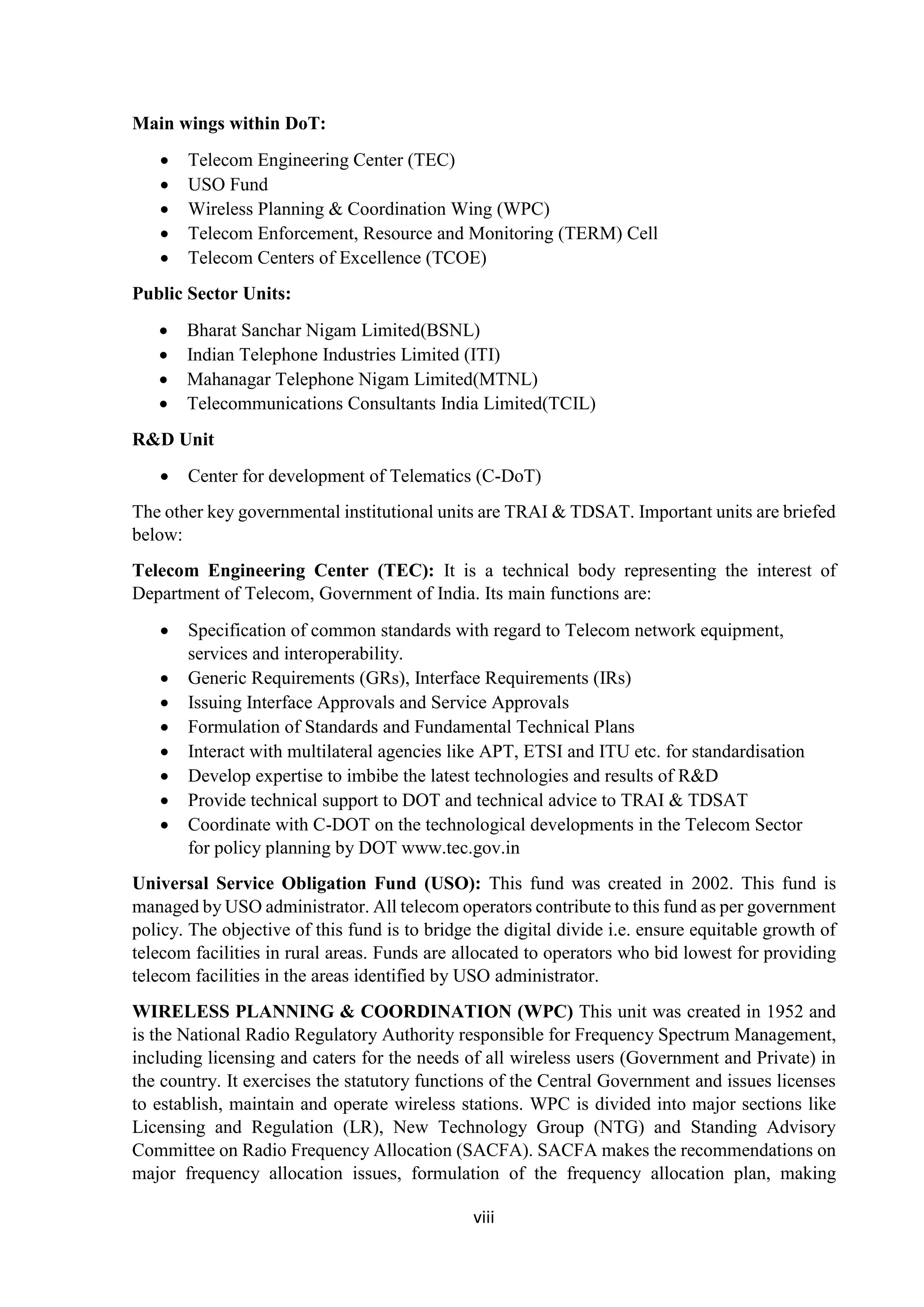
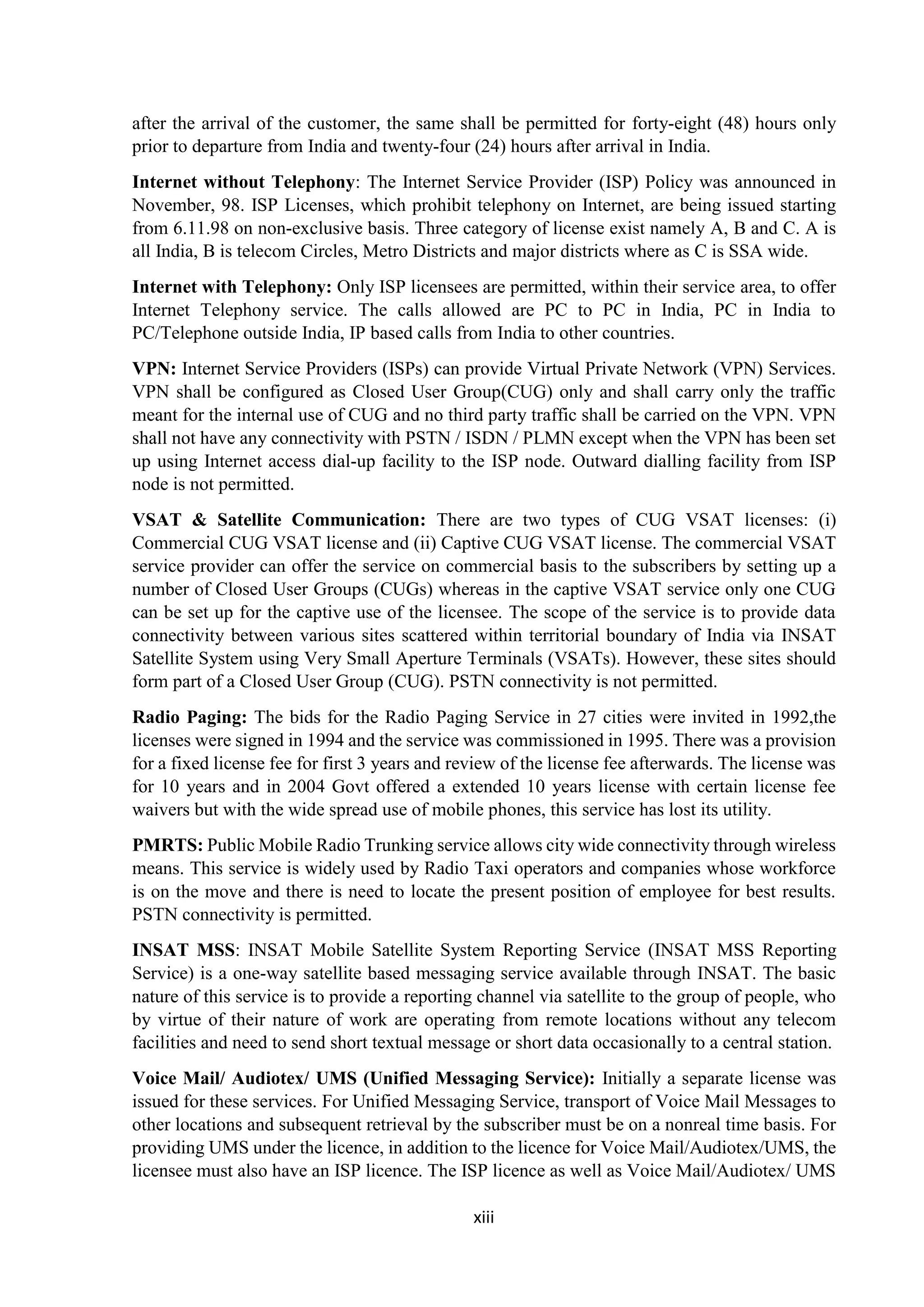
the traditional network has many kinds, such as: telephone network, integrated service digital
network, local area network, the third generation mobile communication system, WLAN,
WATM, satellite communication system, virtual private network etc. The different networks
bear different services (including voice, data, video, image, fax etc.) and have their own
communication platform for bearing and multiple access technologies. In today's various
networks technologies, the trends in networking technology very much point to dominance of
Internet technology with all its flavors. IP is the key technology to enable the exchange of data
across various networks. There is, however, an increasing divergence in the network control
layer: different control environments are established to facilitate services like virtual private
networks, quality of service (QoS), mobility, security, multicast, network address translation,
and so on. For a multitude of services, data might still be handled by uniform Internet
networking [1], with the increase of the ratio of IP data service to telecom service, the
architecture of network is taking the essential changes. The network designed for voice and
narrowband must match in cross layers (protocol and network, channel and modulation) and
optimize (joint source and channel coding, QoS control, horizontal and vertical handover) and
normalize network behavior (Small world, Scale Free). And, it must modulate and control
network resource and behavior. We aid to increases the overlay network layer built on top of
existing networks, is called knowledge management layer. The overlay network layer is peer -
to - peer networks deployed new software and new hardware on top of IP edge router or media
Gateway. nodes in existing networks, to realize the information sharing and cooperation of
heterogeneous networks. This new view of network architecture has the effective management
of information sharing, cooperative working, all - IP-based mobility security, and network
composition by matching and control of the network state, behavior, and resource. Through
these measures, the network can adapt to the transmission demands of the stream medium with
wide band and All-IP, and make use of the IP frames to bear the stream medium services of
voice, data, image, video etc. So, it substitutes the mode that voice bears data and realizes the
reliable transmission of the stream medium of voice, data, video etc in based on all-IP-based
mobile network.
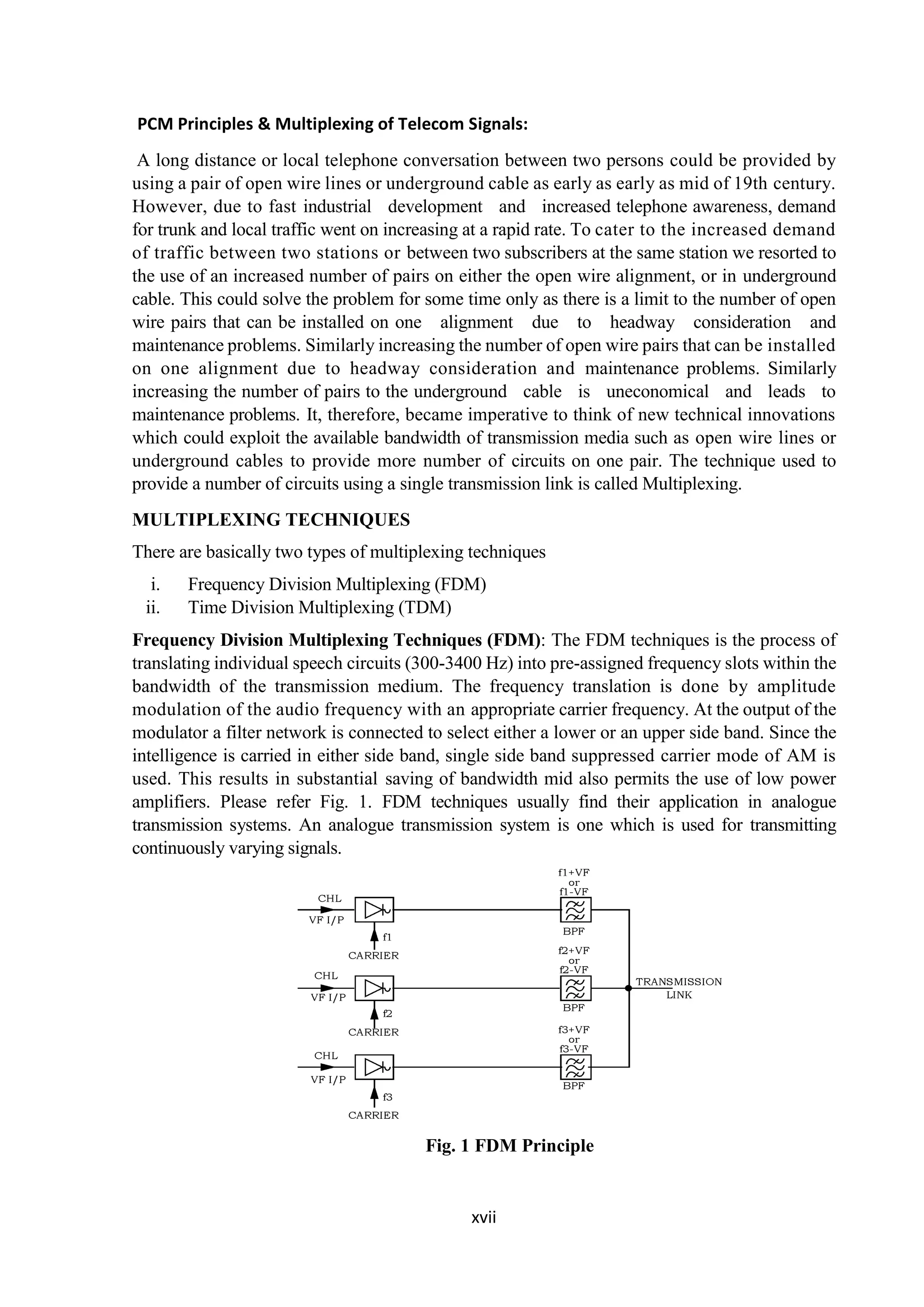
Fig : Flow monitoring in next-generation network](https://image.slidesharecdn.com/bsnlfinalreportnandu1-181031152521/75/REPORT-ON-ADVANCED-TELECOM-52-2048.jpg)
The document is an industrial training report by Ashish Nandan detailing his experience at Advanced Telecom of Makaut University, supervised by Mr. Subhabrata Banerjee. It covers various aspects of telecommunication networks, digital and mobile communications, and the institutional framework governing the telecom sector in India. The report highlights the evolution of telecom reforms, the role of regulatory bodies like TRAI, and significant advancements in communication technologies.


