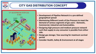
TRAINING PROGRAM
ON CGD NETWORK
Date:01.06.2023
CONTENT
CONCEPT OF CITY GAS DISTRIBUTION
CITY GAS INFRASTRUCTURE
APPLICABLE CODES & STANDARDS
SYSTEM DESIGN
CITY GAS DISTRIBUTION CONCEPT
• Development of Pipeline Network in a pre-defined
geographical spread
• Maintaining Different Levels of Gas Pressure to meet the
Demand of various segments of gas users - Domestic,
Commercial, Industrial and Automobiles.
• Designing high pressure and medium pressure network
such that supply to any consumer is possible from either
side.
• Design gas storage / Gas sourcing for maximum survival
period
• Consider Health, Safety & Environment at all stages
CGD SYSTEM BASIC OUTLINE
HP Network
MPB Network
CITY GATE
Domestic and
Commercial
Users
DRS DRS
DRS
MPA Network
CNG Mother Stations
LP Network
CGD NETWORK LAYOUT
CGD-INFRASTRUCTURE
CGD PRESSURE REGIMES
Sr.
No.
Network Component Inlet from Inlet Pressure Outlet Pressure Outlet to
1 CGS Transmission line 99 - 60 barg 47-26 barg Steel Grid
2 Steel pipeline CGS 47-26 barg 26 – 14 barg DRS / CNG
3 DRS Steel pipeline 26 – 14 barg 4 – 1 barg MP MDPE pipeline
4 Service Regulators (SR) MP MDPE Pipeline 4 – 1 Barg 110 mBarg LP MDPE Pipeline
5 MP MDPE pipeline DRS 4 barg 4 – 1 barg
Industrial MRS &
Commercial
Connections
6 LP MDPE Pipeline SR 110 mBarg 110 – 50 mBarg
Regulator of Domestic /
Commercial
Connections
7 Industrial MRS
MP MDPE pipeline
Steel pipeline
4 – 1.5 barg
26 – 14 barg
1.5 barg or customer
specific pressure within
the supply range
Industrial internal
pipeline
8 Online / Mother CNG Station Steel Pipeline 26 - 14 barg 250 Barg Vehicle at 200 Barg
9 Domestic Connections LP MDPE Pipeline 110 – 50 mBarg 21 mBarg Meter & Gas Stove
10 Commercial Connections
LP MDPE Pipeline
MP MDPE Pipeline
110 – 75 mBarg
4 – 1 Barg
75 mBarg or customer
specific pressure within
the supply range
Meter & Gas Stove
CITY GATE STATION (CGS)
• CGS is the location of Custody Transfer from
Transmission Company to Distribution Company.
BATTERY LIMIT
Distribution Zone
Transmission Distribution
City Gate Station
Transmission
Line
CITY GAS STATION (CGS)
Inlet & Outlet isolation valves
Knock Out Drum (KOD), If required
Filter
Metering Unit (Turbine / Orifice / Ultrasonic)
Gas Chromatograph (GC), If required
Pre-heater (if required)
Pressure reduction skid
• 
Odorising Unit
11
CGS Mahawati , JS GA
12
CGS Mahawati , JS GA
PNG NETWORK
ACTIVITIES OF PNG PROJECTS
ROUTE SURVEY NETWORK DESIGN LIASIONING WITH CIVIC
AGENCY
APPLYING PERMISSION/ SUBMIT
RR CHARGE AND GETTING
PERMISSION
TRENCHING , LAYING
AND JOINTING
TESTING AND
COMISSIONING
MDPE NETWORK
HANDOVER TO O &M
GI/ CU INSTALLATION-
RFC STARTING OF PNG SUPPLY- NG
CGD PROJECT MANAGEMENT
DetailDesign& Engineering Planning& Schedules Tendering/ Orderingof
equipment& material
• ProcurementStrategy
• Identification of materials &
works
• Packaging for tendering &
execution
 ProcessDesignBasis
 Preparation
Specifications
 Listing of equipment
 Processflow diagrams
 PipelineSizing
 MaterialRequisitions
 Receipt/ Dispatch
 Activity-wise plans and
schedule
 Overall Project Schedule
&Plan
 Financial Commitment
Schedule
 Cashflow Plan
• Material & package cost
estimation
• Mode of tendering inline
with C& P Procedure
• Preparation of Master
Vendor List
CGD PROJECT MANAGEMENT
Inspection& Expeditingof
equipment & material
Construction Management
& Supervision
ProjectCommissioning
 Category wise detailed
Plan & Methodology
for inspection
 Methodology for release of
materials after inspection
 Deployment schedule of
manpower for inspection
 Identification &
finalization of number
of packages in line with
MWP
 Certification of
contractor bills
 Methodology for
Commissioning & start
up
 Preparation of O&M
Manual
 Disaster Management
Plan
 EmergencyAction Plan
 Health, Safety &
EnvironmentPlan
INTERNATIONAL STANDARDS
S. No. STANDARD NO. DESCRIPTION
1 EN 12186
Gas supply systems - Gas Pressure
Regulating Stations for Transmission and
Distribution. Functional Requirements
2 EN 12279
Gas pressure regulating - installations on
service lines
3 EN 1776
Gas supply systems - Natural gas measuring
stations - Functional requirements
4 EN 1594
Gas supply systems- Pipeline for maximum
operating pressure over 16 bar- Functional
requirements
INTERNATIONAL STANDARDS
S. No. STANDARD NO. DESCRIPTION
1 ASME B16.11 Forged Steel Fittings, Socket-Welding and Threaded
2 ASME B31.3 Process Piping
3 ASME B31.8 Gas Transmission and Distribution Piping Systems
4 ASME B16.5 Pipe line flanges and flanged fittings
5 ASME B16.9 Factory - Made Wrought Steel Butt welding Fittings
6
ASME- Boiler and Pressure
Vessel Code
Section- IX- Qualification Standard for Welding and
Brazing Procedures, Welders, Brazers, and Welding
and Brazing Operators
7
ASME Boiler and Pressure
Vessel Code- II
Part C- Specifications for welding Rods, Electrodes,
and Filler Metals
8
ASME Boiler & Pressure
Vessel Code
Section - V, Non-destructive Examination
9
ASME Boiler and Pressure
Vessel Code
Section-II Materials Part A- Ferrous Material
Specifications -
INTERNATIONAL STANDARDS
S. No. STANDARD NO. DESCRIPTION
1 ISO- 15590-1
International Standard for Petroleum and natural gas
industries - Induction bends, fittings and flanges for
pipeline transportation systems
2 BS 6755: Part 2 Testing of Valves
3 DIN 30672, Part I
Coatings of corrosion protection tapes and heat-
shrinking products for pipelines for operational
temperatures upto 50oC
4 DIN 30670 Polyethylene coatings for steel pipes and fittings
OIL INDUSTRY SAFETY DIRECTORATE (OISD STANDARDS)
S. No. STANDARD NO. DESCRIPTION
1 OISD-226
Natural Gas Transmission Pipelines & City Gas
Distribution Networks
2 OISD-GDN-115
Guidelines on Fire Fighting, Equipment and
Appliances in Petroleum Industry
3
Fire Protection Manual-
TAC
Fire Engines, Trailer Pumps and Hydrant
Systems
4 OISD- Standard- 141
Design and Construction requirements for cross
country hydrocarbon pipelines
5 OISD-Std-118 Layouts for Oil and Gas Installations
INTERNATIONAL STANDARDS
S. No. STANDARD NO. DESCRIPTION
1 API Standard 1104
Welding of Pipelines and Related
Facilities
2 API Specification 5L Specification for Line pipe
3 API Spec. 6D
Specification for Pipeline Valves ( Gate,
Plug, Ball and Check Valves)
4 API Standard 1102
Specification for steel pipeline crossing
& highways.
INTERNATIONAL STANDARDS
S. No. STANDARD NO. DESCRIPTION
1 AGA Purging Principles and Practices
2 IGE/TD/1
Steel Pipelines for High Pressure Gas
Transmission
3 AGA: Report No. 7 Measurement of Gas by Turbine Meters
4 AGA Report No.3
Orifice metering of Natural Gas and other
related Hydrocarbon fluids
5 AGA-Report No 8
Compressibility factors of Natural Gas and
other related Hydrocarbon gases
RELATED CODES & STANDARDS
Material standard:-
• API 5L / ISO 3183 -Specification for Line Pipe
• API 6D / ISO 14313-Pipeline Valves
Other codes:-
• API RP1102-Recommended practice for Rail and Highway
crossings
• API 1104-Standard for welding pipeline and related facilities
• DNV OS-F101-Submarine pipeline systems
PIPELINE CROSSING STANDARD
• ROU & Land Acquisition-Central/State Govt. as applicable (As per PMP Act
1962)
• National Highway Crossings-NHAI
• SH/ MDR/ ODR Crossings-PWD
• Railway Track crossings-Indian Railways
• Crossing through Forest land-Forest Authority
• River/Canal crossings-Irrigation/Canal Authority
RELATED CODES & STANDARDS
REGULATIONS GOVERNING CGD NETWORKS/ NATURAL GAS P/LS
Other Applicable PNGRB REGULATIONS
S
No.
Regulation for CGD Connotation
1 Guidelines for supplies to I&C customers Scope between entity and customer, cost and
safety
2 Guidelines for supply to Multi-occupancy residential buildings Tertiary network up to stove, feasibility, maintain
records
3 Commissioning and Gas charging of steel pipelines Guideline for safe commissioning, maintaining
reports/records
4 Emergency Response and Disaster Management Plan Preparedness and relief during emergency
5 Declaring pipeline as Common Carrier or Contract Carrier Opportunity for competition
Consumer friendly
6 Methodology for determination of capacity for pipeline and CGD Networks Service to customer.
Level platform during bidding
Spare Capacity for third party
STEPS OF DESIGN
Requirement Analysis
 Source Details
 Availability of Product
 Pressure, Temperature
 Quality
 Geographical Location
 Demand Details
 No of Delivery Point
 Delivery Requirement
 Forecasting of Demand for Designed Life of pipeline
 Geographical distribution of customers
STEPS OF DESIGN
Feasibility Study
 Route Study
 Shortest Route- NHAI-Expressway corridor/ PM&P Act/ Utilities Act etc.
 Least constraints
 Minimum no. of crossings
 Minimum Civic authorities
 Hydraulics Study
 Design Capacity
 Operating Capacity
 Pressure Drop
 Requirement of Boosting station
 Project Cost Estimation
 Implementation Plan
 Environment Impact Assessment
 Risk Analysis
STEPS OF DESIGN
Basic Engineering
 Process Design and Sizing
 Optimization Studies
 Economic optimization
 Process optimization
 Sizing optimization
 Route Surveys
 Detailed Route Surveys of shortlisted ones
 Investigation of routes with
• Other utilities operators
• Construction equipment providers
• General public
• Civic Authorities
STEPS OF DESIGN
Detailed Engineering
• Engineering Design Basis
• Route Engineering and Analysis
• Defining Chainage
• Elevation Profiles
• Crossing Profiles
• Spur line Profiles
• Specifications and Job Standards
• Engineering for Procurement
• Installation Engineering and Construction Procedures based on
applicable codes & standards
STEPS IN THE DESIGN OF GAS DISTRIBUTION SYSTEM
• Demand is estimated based on survey of units covering
domestic, commercial, industrial and transport sectors.
• Demand forecast projection is carried out for 20-25 years.
• Peak hour consumption estimated for network design.
• The system is designed for 20-25th year projected demand
at peak load in a phased manner.
• Reconnaissance Route Survey to identify suitable routes
for laying pipelines, locations for CGS, DRS & CNG Station
STEPS IN THE DESIGN OF GAS DISTRIBUTION SYSTEM
• Network design and optimization with available software
• Steel
• MDPE
• Design of PNG Domestic & Industrial facilities
• Design of Mother Station and Daughter / Daughter booster
station for CNG supply to automobiles
• National / International standards and industry best
practices adopted for design.
INTERDISTANCE- CNG FACILITIES (OISD-179)
INTERDISTANCE –T4S
PIPELINE NETWORK DESIGN
• Supply and demand centres
• Transmission P/Line, STPL and City Gate Station
• Network simulation with future & 3rd party demand
• Codal Requirement of Steel pipelines, ASME 31.8,
• Laying Methodology
• Corrosion Control (Cathodic Protection - TCP & PCP),
• Codal Requirement of MDPE pipelines,
• Laying Methodology,
• Various fittings, jointing, saddle & transition fittings
PIPELINE THROUGHPUT VS DIAMETER
PIPELINE DESIGN
• Consideration:- ROUTE SELECTION
• Pipeline length
• Obstructions & Sensitive areas
• Installation Limitations
• Crossings
• Surveys:-
• Topographical
• Geo-technical
• Population Density Index
• Soil Resistivity
PIPELINE DESIGN (MATERIAL SELECTION)
• Materials:-
• Carbon Steel
• Alloy Steel
• Coated Carbon Steel
• Non Metallic Material
• Consideration:-
• Nature of product
• Product Temperature & Pressure
• Design life
• Material Chemistry
• Coating Requirement
• Product Conditioning
• Corrosion Inhibitors
• Corrosion Allowance
SOFTWARE USED
• SynerGEE GAS - Network modeling for gas
distribution and transmission
• PIPELINE STUDIO - Pipeline design, planning and
hydraulic analysis
• AUTO PIPE - Pipeline stress analysis
• OFFPIPE - FEA modelling and structure
analysis
• HYSIS - Material flow simulation analysis
• CAESAR - Pipeline flexibility and load
analysis
• TL NET - flow transfer study in single phase
• TG NET - flow transfer study in single phase
• GASWORKS - Simulation & modelling software
SynerGEE Gas
Inputs from design philosophy:
1. Pipeline sizing, in general, is carried out by ‘Panhandle (A)’ formula.
2. Efficiency of Pipe line - 90%
3. Roughness of Pipe line - 65.4 micron
4. The proposed route and length of Transmission network is estimated
based on a detailed route survey, desktop study, load profile,
population density, proximity to buildings, EIA and HAZOP as
applicable.
CONFIGURED SETTINGS
Min and Max - Design Pressure Constraints.
Velocity – Optimum and Maximum
Base values - Atmospheric Press, Temp
Pressure & Elevation.
GAS properties - Heat content, Specific Gravity,CO2
content, Viscosity
Node Properties - Max Allowable pressure, Min.
Allowable pressure, Source Gas Temp
Pipe properties - Efficiency ,Friction factor, Roughness,
Gas flow Temp.
Outputs from SynerGEE Gas
1. Minimum pressure in the network
2. Maximum velocity in the network
3. Flow as obtained by diversity factor.
4. Detailed customized reports
SynerGEE Gas
STRESS IN PIPELINE
• Hoop Stress- Hoop Stress remains constant through out the wall
thickness and equal to
σh = PD/2t
P = design pressure, psi
D= Outside diameter, in
t = pipe wall thickness
• Longitudinal Stress- it also remains constant throughout the wall
thickness and equal to half of Hoop stress-
σl = PD/4t
PIELINE DESIGN EQUATION
• For Gas Pipeline, Allowable Stress is (ASME B31.8)
S= SYFET
SY= specified minimum yield stress, psi.
F= design Factor,
E= weld joint factor
T= Temperature derating factor.
WALL THICKNESS ANALYSIS
GAS PIPELINE (ASME B 31.8, Cl. 841.11)
t= PD/ 2SFET
Where
t Nominal wall thickness
P Design Pressure
S Specified Minimum Yield Strength
F Design factor
E Longitudinal Joint Factor
T Temperature De-rating Factor
D Out side Diameter of pipe
LONGITUDINAL DESIGN FACTOR (E)
PIPELINE DESIGN (LOCATION CLASSIFICATION)
Location Class Basis (No. of buildings ,X) Design Factor (F)
Location Class- 1 X≤ 10 0.72
Location Class- 2 10<X<46 0.60
Location Class- 3 X>46 0.50
Location Class- 4 Multistory 0.40
MINIMUM YIELD STRENGTH(PSI)
Specifications MYS(psi)
API 5LX Grade X42 42,000
API 5LX Grade X46 46,000
API 5LX Grade X52 52,000
API 5LX Grade X56 56,000
API 5LX Grade X60 60,000
API 5LX Grade X65 65,000
API 5LX Grade X70 70,000
API 5LX Grade X80 80,000
API 5LX Grade X90 90,000
EXERCISE
What is the nominal wall thickness for a 42 inch submerged arc welded pipeline designed for 800
psi pressure operating in a densely populated area. The pipeline is of the type 5LX G-80 and product
operating temperature 40’C.
t= PD/ 2SFET
P Design Pressure = 800 PSI
D Out side Diameter of pipe = 42 inch
S Specified Minimum Yield Strength =
F Design factor =
E Longitudinal Joint Factor =
T Temperature De-rating Factor =
t= (800 X 42) / ( 2 X 80000 X 0.40 X 1 X 1)= 0.525 inch
POLYETHENELENE PIPELINE
MRS(Minimum Required Strength)
The MRS value represents the long-term circumferential stress in the pipe under which
the break may occur after 50years at the earliest.
Stress = MRS/ C, where C is overall service coefficient
The minimum value of C for the material to be used for Gas application is 2.
MAOP(Max. allowableOperatingPressure)
MAOP= (20* MRS) / [C * (SDR-1)].
Standard Dimension Ratio
SDR= Dn / En
Standard followed by CGD entities - IS 14885:2001
POLYETHENELENE PIPELINE
Base resin
• The PE resins of “Third Generation” (PE 100 or MRS 10) in full compliance
with detailed specification is being used. First Generation is PE 63, second PE 80 &
Third generation is PE 100.
Wall thickness
• The MDPE network designed and qualified for a MOP of 4 bar.
• The “Network analysis” and resulting structure and behaviors are based
on such design. PE line pipes wall thickness shall be in accordance with
the following SDR
• Gas mains (ND≥ 90mm):SDR17.6
• Gas mains and Service lines (ND≤ 90mm):SDR11.
• Service lines (ND= 20mm): SDR9
POLYETHELENE PIPELINE
 Process Design
• Wey-mouth Formulae ◦
Q = 0.11672 * (d)2.664 * {(p12-p22)0.544 / (S * L)1/2}
• Velocity
V = Q / A
Velocity for filtered gas to be 40 m/s & unfiltered gas to
be 20 m/s.
• Being a complex network, required specialized tools for
Planning & Designing the network.
• Synergee software for designing the PE Network is generally
used.
PNG DOMESTIC & COMMERCIAL CONNECTION
 Process Design
• ◦Poly flow Formulae
• ◦ Q = 1.522786 * 10-3 * (d)2.623 * {(h/L)0.541}
• Peak Gas flow is assumed @ 0.4 SCMH for one house
• Standardize the design of PNG Network as follows;
• ½”GI pipes up to G +4 apartments OR 5 connections in case
of raw house.
• 1”GI Pipe above 5th Floor apartment OR above five
connections in raw house
PNG DOMESTIC & COMMERCIAL CONNECTION
TYPES OF PIPELINE COATING
• COAL TAR ENAMEL (CTE)
• FUSION BONDED EPOXY (FBE), SINGLE AND DUAL LAYER
• 3 LAYER POLYETHYLENE (3LPE)
• 3 LAYER POLYPROPYLENE (3LPP)
LINE PIPE COATING
Desirable Characteristics of coating
• Effective Electrical Insulator
• Effective moisture Barrier
• Ability to Resist Development of Holidays
• Adhesion to Pipe Surface
• Ease of Repair
• Non Toxic Interaction with Environment
• Hardness / Abrasion Resistance
• Penetration Resistant
• Soil Stressing Resistant
IRON OXIDE TO STEEL TO IRON OXIDE CYCLE
• Materials:-
• Carbon Steel
• Alloy Steel
• Coated Carbon Steel
• Non Metallic Material
• Consideration:-
• Nature of product
• Product Temperature & Pressure
• Design life
• Material Chemistry
• Coating Requirement
• Product Conditioning
• Corrosion Inhibitors
ANODIC & CATHODIC REACTIONS
• Anodic reaction : Fe Fe + 2e
• Cathodic reaction : ½ O + H O +2e 2OH
• Fe and 2OH react further to form ferrous hydroxide precipitate :
Fe + 2OH Fe (OH)
Ferrous hydroxide is oxidized to ferric hydroxide
Fe(OH) + ½ O + ½ H O Fe(OH)
If ferric hydroxide is dry, the hydroxide sludge dehydrates to form insoluble
ferric oxide which known as rust :
2Fe (OH) Fe O + 3 H O
Fe O , FeO , Fe(OH) , Fe(OH) are found as corrosion products
on metal surface.
CORROSION MITIGATION FOR EXTERNAL SURFACE
CRITERIA OF C.P. FOR STEEL AND CAST IRON
Pipeline AS PER NACE SP0169
• A negative ( Cathodic) potential of at least
850 mV with the cathodic protection applied.
These potential is measured with respect to
saturated Copper/ Copper Sulphate reference
electrode contacting electrolyte.
• A Minimum of 100 mV of Cathodic
Polarization between the Pipeline surface and
a stable reference electrode contacting the
electrolyte. The formation of decay of
Polarization can be measured to satisfy the
criterion.
THREE LAYER PE COATING
FITTINGS & FLANGES
Sr. No Description Specification
1. Elbows up to 2” ASTM A 234, Sch 80
2. Elbows above 2” ASTM A 234, Sch 40
3. Tees ASTM A 216
4. Flanges & Blinds ASTM A 105, 300#
5. Reducers ASTM A 216
6. Weldolets ASTM A 105, 300#
7. Insulation Joints ASTM A 105, 300#
GLOBE VALVE
Used to regulate
flow
Cut-away shows stem
seal
plug
and seat
BALL VALVE
Typically used as
block valve
“Quarter-turn” valve
Cut-away shows ball
and seat
CHECK VALVE
Used to prevent
backflow
Piston check
Swing check
SECTIONALIZING VALVE (SV)STATION
• Used to isolate gas pipeline network in case of planned shut
down or in emergency situation.
• Spacing as per ASME B 31.8 for gas pipeline
• As per T4S amendment dated 25.09.2020,interdistance can be
enhanced beyond municipal areas + buffer.
Location Class Inter distance of SVs
Location Class- 1 32 KMs
Location Class- 2 24 KMs
Location Class- 3 16 KMs
Location Class- 4 8 KMs
Municipal Areas 3 KMs
MAIN ENGINEERING REPORT COMPONENTS
• Reports:-
• Design Basis
• Route Selection Report
• Wall Thickness Analysis
• Seismic Design Report
• Crossing Design Report
• Drawings:-
• Route Map
• Pipeline Schematic & Alignment
• SV & Chamber
• Other General Drawings
Thank You
FOR CGD
• Available Gas Source
• Geographical analysis of city
• Area of city
• Location, near by cities
• Segmentation of city into charge areas
• Major Highways passing through city
• Population
• Identification of Industrial area
• Commercials
• Infrastructure planning like Hospital, schools & other town planning
• Demand forecasting based on future planning
FOR CGD
• Route finalization based on
• Load distribution
• Future demand
• Vehicle movement details
• Trend of Increase in vehicles
• Field surveys for industrial & commercial
• Dispute of land owners with Govt. on land acquisition
• Sizing of pipe line
• Present load
• Demand build up
• Segment wise potential & realizable demand
DEMAND BUILD UP
FOR CGD
• Route finalization based on
• Load distribution
• Future demand
• Vehicle movement details
• Trend of Increase in vehicles
• Field surveys for industrial & commercial
• Dispute of land owners with Govt. on land acquisition
• Sizing of pipe line
• Present load
• Demand build up
• Segment wise potential & realizable demand
CNG SUPPLY CHAIN
CNG
Compressor
Storage
Cascade
Dispenser
CNG
Vehicle
Mobile
Cascade
Mobile
Cascade
Mobile
Cascade
Booster
Dispenser
CNG
Vehicle
Mobile
Cascade
Dispenser
CNG
Vehicle
CNG
Compressor
Storage
Cascade
Dispenser
CNG
Vehicle
19-22 Kg/cm2g
<=200 Kg/cm2g
<=200 Kg/cm2g <=200 Kg/cm2g
19-22 Kg/cm2g
250 Kg/cm2g
<=200 Kg/cm2g
STEEL PIPELINE – NATURAL GAS CARRIER
MOTHER
STATION
DAUGHTER
BOOSTER STATION
DAUGHTER
STATION
ONLINE
STATION
EXAMPLE
P 1 = 15 Barg, P2 = 10 Barg (Min.)

Refresher_City Gas network & Design.pptx

  • 1.
    TRAINING PROGRAM ON CGDNETWORK Date:01.06.2023
  • 2.
    CONTENT CONCEPT OF CITYGAS DISTRIBUTION CITY GAS INFRASTRUCTURE APPLICABLE CODES & STANDARDS SYSTEM DESIGN
  • 3.
    CITY GAS DISTRIBUTIONCONCEPT • Development of Pipeline Network in a pre-defined geographical spread • Maintaining Different Levels of Gas Pressure to meet the Demand of various segments of gas users - Domestic, Commercial, Industrial and Automobiles. • Designing high pressure and medium pressure network such that supply to any consumer is possible from either side. • Design gas storage / Gas sourcing for maximum survival period • Consider Health, Safety & Environment at all stages
  • 4.
    CGD SYSTEM BASICOUTLINE HP Network MPB Network CITY GATE Domestic and Commercial Users DRS DRS DRS MPA Network CNG Mother Stations LP Network
  • 5.
  • 6.
  • 7.
    CGD PRESSURE REGIMES Sr. No. NetworkComponent Inlet from Inlet Pressure Outlet Pressure Outlet to 1 CGS Transmission line 99 - 60 barg 47-26 barg Steel Grid 2 Steel pipeline CGS 47-26 barg 26 – 14 barg DRS / CNG 3 DRS Steel pipeline 26 – 14 barg 4 – 1 barg MP MDPE pipeline 4 Service Regulators (SR) MP MDPE Pipeline 4 – 1 Barg 110 mBarg LP MDPE Pipeline 5 MP MDPE pipeline DRS 4 barg 4 – 1 barg Industrial MRS & Commercial Connections 6 LP MDPE Pipeline SR 110 mBarg 110 – 50 mBarg Regulator of Domestic / Commercial Connections 7 Industrial MRS MP MDPE pipeline Steel pipeline 4 – 1.5 barg 26 – 14 barg 1.5 barg or customer specific pressure within the supply range Industrial internal pipeline 8 Online / Mother CNG Station Steel Pipeline 26 - 14 barg 250 Barg Vehicle at 200 Barg 9 Domestic Connections LP MDPE Pipeline 110 – 50 mBarg 21 mBarg Meter & Gas Stove 10 Commercial Connections LP MDPE Pipeline MP MDPE Pipeline 110 – 75 mBarg 4 – 1 Barg 75 mBarg or customer specific pressure within the supply range Meter & Gas Stove
  • 8.
    CITY GATE STATION(CGS) • CGS is the location of Custody Transfer from Transmission Company to Distribution Company.
  • 9.
    BATTERY LIMIT Distribution Zone TransmissionDistribution City Gate Station Transmission Line
  • 10.
    CITY GAS STATION(CGS) Inlet & Outlet isolation valves Knock Out Drum (KOD), If required Filter Metering Unit (Turbine / Orifice / Ultrasonic) Gas Chromatograph (GC), If required Pre-heater (if required) Pressure reduction skid • Odorising Unit
  • 11.
  • 12.
  • 13.
  • 14.
    ACTIVITIES OF PNGPROJECTS ROUTE SURVEY NETWORK DESIGN LIASIONING WITH CIVIC AGENCY APPLYING PERMISSION/ SUBMIT RR CHARGE AND GETTING PERMISSION TRENCHING , LAYING AND JOINTING TESTING AND COMISSIONING MDPE NETWORK HANDOVER TO O &M GI/ CU INSTALLATION- RFC STARTING OF PNG SUPPLY- NG
  • 15.
    CGD PROJECT MANAGEMENT DetailDesign&Engineering Planning& Schedules Tendering/ Orderingof equipment& material • ProcurementStrategy • Identification of materials & works • Packaging for tendering & execution  ProcessDesignBasis  Preparation Specifications  Listing of equipment  Processflow diagrams  PipelineSizing  MaterialRequisitions  Receipt/ Dispatch  Activity-wise plans and schedule  Overall Project Schedule &Plan  Financial Commitment Schedule  Cashflow Plan • Material & package cost estimation • Mode of tendering inline with C& P Procedure • Preparation of Master Vendor List
  • 16.
    CGD PROJECT MANAGEMENT Inspection&Expeditingof equipment & material Construction Management & Supervision ProjectCommissioning  Category wise detailed Plan & Methodology for inspection  Methodology for release of materials after inspection  Deployment schedule of manpower for inspection  Identification & finalization of number of packages in line with MWP  Certification of contractor bills  Methodology for Commissioning & start up  Preparation of O&M Manual  Disaster Management Plan  EmergencyAction Plan  Health, Safety & EnvironmentPlan
  • 17.
    INTERNATIONAL STANDARDS S. No.STANDARD NO. DESCRIPTION 1 EN 12186 Gas supply systems - Gas Pressure Regulating Stations for Transmission and Distribution. Functional Requirements 2 EN 12279 Gas pressure regulating - installations on service lines 3 EN 1776 Gas supply systems - Natural gas measuring stations - Functional requirements 4 EN 1594 Gas supply systems- Pipeline for maximum operating pressure over 16 bar- Functional requirements
  • 18.
    INTERNATIONAL STANDARDS S. No.STANDARD NO. DESCRIPTION 1 ASME B16.11 Forged Steel Fittings, Socket-Welding and Threaded 2 ASME B31.3 Process Piping 3 ASME B31.8 Gas Transmission and Distribution Piping Systems 4 ASME B16.5 Pipe line flanges and flanged fittings 5 ASME B16.9 Factory - Made Wrought Steel Butt welding Fittings 6 ASME- Boiler and Pressure Vessel Code Section- IX- Qualification Standard for Welding and Brazing Procedures, Welders, Brazers, and Welding and Brazing Operators 7 ASME Boiler and Pressure Vessel Code- II Part C- Specifications for welding Rods, Electrodes, and Filler Metals 8 ASME Boiler & Pressure Vessel Code Section - V, Non-destructive Examination 9 ASME Boiler and Pressure Vessel Code Section-II Materials Part A- Ferrous Material Specifications -
  • 19.
    INTERNATIONAL STANDARDS S. No.STANDARD NO. DESCRIPTION 1 ISO- 15590-1 International Standard for Petroleum and natural gas industries - Induction bends, fittings and flanges for pipeline transportation systems 2 BS 6755: Part 2 Testing of Valves 3 DIN 30672, Part I Coatings of corrosion protection tapes and heat- shrinking products for pipelines for operational temperatures upto 50oC 4 DIN 30670 Polyethylene coatings for steel pipes and fittings
  • 20.
    OIL INDUSTRY SAFETYDIRECTORATE (OISD STANDARDS) S. No. STANDARD NO. DESCRIPTION 1 OISD-226 Natural Gas Transmission Pipelines & City Gas Distribution Networks 2 OISD-GDN-115 Guidelines on Fire Fighting, Equipment and Appliances in Petroleum Industry 3 Fire Protection Manual- TAC Fire Engines, Trailer Pumps and Hydrant Systems 4 OISD- Standard- 141 Design and Construction requirements for cross country hydrocarbon pipelines 5 OISD-Std-118 Layouts for Oil and Gas Installations
  • 21.
    INTERNATIONAL STANDARDS S. No.STANDARD NO. DESCRIPTION 1 API Standard 1104 Welding of Pipelines and Related Facilities 2 API Specification 5L Specification for Line pipe 3 API Spec. 6D Specification for Pipeline Valves ( Gate, Plug, Ball and Check Valves) 4 API Standard 1102 Specification for steel pipeline crossing & highways.
  • 22.
    INTERNATIONAL STANDARDS S. No.STANDARD NO. DESCRIPTION 1 AGA Purging Principles and Practices 2 IGE/TD/1 Steel Pipelines for High Pressure Gas Transmission 3 AGA: Report No. 7 Measurement of Gas by Turbine Meters 4 AGA Report No.3 Orifice metering of Natural Gas and other related Hydrocarbon fluids 5 AGA-Report No 8 Compressibility factors of Natural Gas and other related Hydrocarbon gases
  • 23.
    RELATED CODES &STANDARDS Material standard:- • API 5L / ISO 3183 -Specification for Line Pipe • API 6D / ISO 14313-Pipeline Valves Other codes:- • API RP1102-Recommended practice for Rail and Highway crossings • API 1104-Standard for welding pipeline and related facilities • DNV OS-F101-Submarine pipeline systems
  • 24.
    PIPELINE CROSSING STANDARD •ROU & Land Acquisition-Central/State Govt. as applicable (As per PMP Act 1962) • National Highway Crossings-NHAI • SH/ MDR/ ODR Crossings-PWD • Railway Track crossings-Indian Railways • Crossing through Forest land-Forest Authority • River/Canal crossings-Irrigation/Canal Authority
  • 25.
    RELATED CODES &STANDARDS
  • 26.
    REGULATIONS GOVERNING CGDNETWORKS/ NATURAL GAS P/LS
  • 27.
    REGULATIONS GOVERNING CGDNETWORKS/ NATURAL GAS P/LS
  • 28.
    Other Applicable PNGRBREGULATIONS S No. Regulation for CGD Connotation 1 Guidelines for supplies to I&C customers Scope between entity and customer, cost and safety 2 Guidelines for supply to Multi-occupancy residential buildings Tertiary network up to stove, feasibility, maintain records 3 Commissioning and Gas charging of steel pipelines Guideline for safe commissioning, maintaining reports/records 4 Emergency Response and Disaster Management Plan Preparedness and relief during emergency 5 Declaring pipeline as Common Carrier or Contract Carrier Opportunity for competition Consumer friendly 6 Methodology for determination of capacity for pipeline and CGD Networks Service to customer. Level platform during bidding Spare Capacity for third party
  • 29.
    STEPS OF DESIGN RequirementAnalysis  Source Details  Availability of Product  Pressure, Temperature  Quality  Geographical Location  Demand Details  No of Delivery Point  Delivery Requirement  Forecasting of Demand for Designed Life of pipeline  Geographical distribution of customers
  • 30.
    STEPS OF DESIGN FeasibilityStudy  Route Study  Shortest Route- NHAI-Expressway corridor/ PM&P Act/ Utilities Act etc.  Least constraints  Minimum no. of crossings  Minimum Civic authorities  Hydraulics Study  Design Capacity  Operating Capacity  Pressure Drop  Requirement of Boosting station  Project Cost Estimation  Implementation Plan  Environment Impact Assessment  Risk Analysis
  • 31.
    STEPS OF DESIGN BasicEngineering  Process Design and Sizing  Optimization Studies  Economic optimization  Process optimization  Sizing optimization  Route Surveys  Detailed Route Surveys of shortlisted ones  Investigation of routes with • Other utilities operators • Construction equipment providers • General public • Civic Authorities
  • 32.
    STEPS OF DESIGN DetailedEngineering • Engineering Design Basis • Route Engineering and Analysis • Defining Chainage • Elevation Profiles • Crossing Profiles • Spur line Profiles • Specifications and Job Standards • Engineering for Procurement • Installation Engineering and Construction Procedures based on applicable codes & standards
  • 33.
    STEPS IN THEDESIGN OF GAS DISTRIBUTION SYSTEM • Demand is estimated based on survey of units covering domestic, commercial, industrial and transport sectors. • Demand forecast projection is carried out for 20-25 years. • Peak hour consumption estimated for network design. • The system is designed for 20-25th year projected demand at peak load in a phased manner. • Reconnaissance Route Survey to identify suitable routes for laying pipelines, locations for CGS, DRS & CNG Station
  • 34.
    STEPS IN THEDESIGN OF GAS DISTRIBUTION SYSTEM • Network design and optimization with available software • Steel • MDPE • Design of PNG Domestic & Industrial facilities • Design of Mother Station and Daughter / Daughter booster station for CNG supply to automobiles • National / International standards and industry best practices adopted for design.
  • 35.
  • 36.
  • 37.
    PIPELINE NETWORK DESIGN •Supply and demand centres • Transmission P/Line, STPL and City Gate Station • Network simulation with future & 3rd party demand • Codal Requirement of Steel pipelines, ASME 31.8, • Laying Methodology • Corrosion Control (Cathodic Protection - TCP & PCP), • Codal Requirement of MDPE pipelines, • Laying Methodology, • Various fittings, jointing, saddle & transition fittings
  • 38.
  • 39.
    PIPELINE DESIGN • Consideration:-ROUTE SELECTION • Pipeline length • Obstructions & Sensitive areas • Installation Limitations • Crossings • Surveys:- • Topographical • Geo-technical • Population Density Index • Soil Resistivity
  • 40.
    PIPELINE DESIGN (MATERIALSELECTION) • Materials:- • Carbon Steel • Alloy Steel • Coated Carbon Steel • Non Metallic Material • Consideration:- • Nature of product • Product Temperature & Pressure • Design life • Material Chemistry • Coating Requirement • Product Conditioning • Corrosion Inhibitors • Corrosion Allowance
  • 41.
    SOFTWARE USED • SynerGEEGAS - Network modeling for gas distribution and transmission • PIPELINE STUDIO - Pipeline design, planning and hydraulic analysis • AUTO PIPE - Pipeline stress analysis • OFFPIPE - FEA modelling and structure analysis • HYSIS - Material flow simulation analysis • CAESAR - Pipeline flexibility and load analysis • TL NET - flow transfer study in single phase • TG NET - flow transfer study in single phase • GASWORKS - Simulation & modelling software
  • 42.
    SynerGEE Gas Inputs fromdesign philosophy: 1. Pipeline sizing, in general, is carried out by ‘Panhandle (A)’ formula. 2. Efficiency of Pipe line - 90% 3. Roughness of Pipe line - 65.4 micron 4. The proposed route and length of Transmission network is estimated based on a detailed route survey, desktop study, load profile, population density, proximity to buildings, EIA and HAZOP as applicable.
  • 43.
    CONFIGURED SETTINGS Min andMax - Design Pressure Constraints. Velocity – Optimum and Maximum Base values - Atmospheric Press, Temp Pressure & Elevation. GAS properties - Heat content, Specific Gravity,CO2 content, Viscosity Node Properties - Max Allowable pressure, Min. Allowable pressure, Source Gas Temp Pipe properties - Efficiency ,Friction factor, Roughness, Gas flow Temp.
  • 44.
    Outputs from SynerGEEGas 1. Minimum pressure in the network 2. Maximum velocity in the network 3. Flow as obtained by diversity factor. 4. Detailed customized reports
  • 45.
  • 46.
    STRESS IN PIPELINE •Hoop Stress- Hoop Stress remains constant through out the wall thickness and equal to σh = PD/2t P = design pressure, psi D= Outside diameter, in t = pipe wall thickness • Longitudinal Stress- it also remains constant throughout the wall thickness and equal to half of Hoop stress- σl = PD/4t
  • 47.
    PIELINE DESIGN EQUATION •For Gas Pipeline, Allowable Stress is (ASME B31.8) S= SYFET SY= specified minimum yield stress, psi. F= design Factor, E= weld joint factor T= Temperature derating factor.
  • 48.
    WALL THICKNESS ANALYSIS GASPIPELINE (ASME B 31.8, Cl. 841.11) t= PD/ 2SFET Where t Nominal wall thickness P Design Pressure S Specified Minimum Yield Strength F Design factor E Longitudinal Joint Factor T Temperature De-rating Factor D Out side Diameter of pipe
  • 49.
  • 50.
    PIPELINE DESIGN (LOCATIONCLASSIFICATION) Location Class Basis (No. of buildings ,X) Design Factor (F) Location Class- 1 X≤ 10 0.72 Location Class- 2 10<X<46 0.60 Location Class- 3 X>46 0.50 Location Class- 4 Multistory 0.40
  • 51.
    MINIMUM YIELD STRENGTH(PSI) SpecificationsMYS(psi) API 5LX Grade X42 42,000 API 5LX Grade X46 46,000 API 5LX Grade X52 52,000 API 5LX Grade X56 56,000 API 5LX Grade X60 60,000 API 5LX Grade X65 65,000 API 5LX Grade X70 70,000 API 5LX Grade X80 80,000 API 5LX Grade X90 90,000
  • 52.
    EXERCISE What is thenominal wall thickness for a 42 inch submerged arc welded pipeline designed for 800 psi pressure operating in a densely populated area. The pipeline is of the type 5LX G-80 and product operating temperature 40’C. t= PD/ 2SFET P Design Pressure = 800 PSI D Out side Diameter of pipe = 42 inch S Specified Minimum Yield Strength = F Design factor = E Longitudinal Joint Factor = T Temperature De-rating Factor = t= (800 X 42) / ( 2 X 80000 X 0.40 X 1 X 1)= 0.525 inch
  • 53.
    POLYETHENELENE PIPELINE MRS(Minimum RequiredStrength) The MRS value represents the long-term circumferential stress in the pipe under which the break may occur after 50years at the earliest. Stress = MRS/ C, where C is overall service coefficient The minimum value of C for the material to be used for Gas application is 2. MAOP(Max. allowableOperatingPressure) MAOP= (20* MRS) / [C * (SDR-1)]. Standard Dimension Ratio SDR= Dn / En Standard followed by CGD entities - IS 14885:2001
  • 54.
    POLYETHENELENE PIPELINE Base resin •The PE resins of “Third Generation” (PE 100 or MRS 10) in full compliance with detailed specification is being used. First Generation is PE 63, second PE 80 & Third generation is PE 100. Wall thickness • The MDPE network designed and qualified for a MOP of 4 bar. • The “Network analysis” and resulting structure and behaviors are based on such design. PE line pipes wall thickness shall be in accordance with the following SDR • Gas mains (ND≥ 90mm):SDR17.6 • Gas mains and Service lines (ND≤ 90mm):SDR11. • Service lines (ND= 20mm): SDR9
  • 55.
    POLYETHELENE PIPELINE  ProcessDesign • Wey-mouth Formulae ◦ Q = 0.11672 * (d)2.664 * {(p12-p22)0.544 / (S * L)1/2} • Velocity V = Q / A Velocity for filtered gas to be 40 m/s & unfiltered gas to be 20 m/s. • Being a complex network, required specialized tools for Planning & Designing the network. • Synergee software for designing the PE Network is generally used.
  • 56.
    PNG DOMESTIC &COMMERCIAL CONNECTION  Process Design • ◦Poly flow Formulae • ◦ Q = 1.522786 * 10-3 * (d)2.623 * {(h/L)0.541} • Peak Gas flow is assumed @ 0.4 SCMH for one house • Standardize the design of PNG Network as follows; • ½”GI pipes up to G +4 apartments OR 5 connections in case of raw house. • 1”GI Pipe above 5th Floor apartment OR above five connections in raw house
  • 57.
    PNG DOMESTIC &COMMERCIAL CONNECTION
  • 58.
    TYPES OF PIPELINECOATING • COAL TAR ENAMEL (CTE) • FUSION BONDED EPOXY (FBE), SINGLE AND DUAL LAYER • 3 LAYER POLYETHYLENE (3LPE) • 3 LAYER POLYPROPYLENE (3LPP)
  • 59.
    LINE PIPE COATING DesirableCharacteristics of coating • Effective Electrical Insulator • Effective moisture Barrier • Ability to Resist Development of Holidays • Adhesion to Pipe Surface • Ease of Repair • Non Toxic Interaction with Environment • Hardness / Abrasion Resistance • Penetration Resistant • Soil Stressing Resistant
  • 60.
    IRON OXIDE TOSTEEL TO IRON OXIDE CYCLE • Materials:- • Carbon Steel • Alloy Steel • Coated Carbon Steel • Non Metallic Material • Consideration:- • Nature of product • Product Temperature & Pressure • Design life • Material Chemistry • Coating Requirement • Product Conditioning • Corrosion Inhibitors
  • 61.
    ANODIC & CATHODICREACTIONS • Anodic reaction : Fe Fe + 2e • Cathodic reaction : ½ O + H O +2e 2OH • Fe and 2OH react further to form ferrous hydroxide precipitate : Fe + 2OH Fe (OH) Ferrous hydroxide is oxidized to ferric hydroxide Fe(OH) + ½ O + ½ H O Fe(OH) If ferric hydroxide is dry, the hydroxide sludge dehydrates to form insoluble ferric oxide which known as rust : 2Fe (OH) Fe O + 3 H O Fe O , FeO , Fe(OH) , Fe(OH) are found as corrosion products on metal surface.
  • 62.
    CORROSION MITIGATION FOREXTERNAL SURFACE CRITERIA OF C.P. FOR STEEL AND CAST IRON Pipeline AS PER NACE SP0169 • A negative ( Cathodic) potential of at least 850 mV with the cathodic protection applied. These potential is measured with respect to saturated Copper/ Copper Sulphate reference electrode contacting electrolyte. • A Minimum of 100 mV of Cathodic Polarization between the Pipeline surface and a stable reference electrode contacting the electrolyte. The formation of decay of Polarization can be measured to satisfy the criterion.
  • 63.
  • 64.
    FITTINGS & FLANGES Sr.No Description Specification 1. Elbows up to 2” ASTM A 234, Sch 80 2. Elbows above 2” ASTM A 234, Sch 40 3. Tees ASTM A 216 4. Flanges & Blinds ASTM A 105, 300# 5. Reducers ASTM A 216 6. Weldolets ASTM A 105, 300# 7. Insulation Joints ASTM A 105, 300#
  • 65.
    GLOBE VALVE Used toregulate flow Cut-away shows stem seal plug and seat
  • 66.
    BALL VALVE Typically usedas block valve “Quarter-turn” valve Cut-away shows ball and seat
  • 67.
    CHECK VALVE Used toprevent backflow Piston check Swing check
  • 68.
    SECTIONALIZING VALVE (SV)STATION •Used to isolate gas pipeline network in case of planned shut down or in emergency situation. • Spacing as per ASME B 31.8 for gas pipeline • As per T4S amendment dated 25.09.2020,interdistance can be enhanced beyond municipal areas + buffer. Location Class Inter distance of SVs Location Class- 1 32 KMs Location Class- 2 24 KMs Location Class- 3 16 KMs Location Class- 4 8 KMs Municipal Areas 3 KMs
  • 69.
    MAIN ENGINEERING REPORTCOMPONENTS • Reports:- • Design Basis • Route Selection Report • Wall Thickness Analysis • Seismic Design Report • Crossing Design Report • Drawings:- • Route Map • Pipeline Schematic & Alignment • SV & Chamber • Other General Drawings
  • 70.
  • 71.
    FOR CGD • AvailableGas Source • Geographical analysis of city • Area of city • Location, near by cities • Segmentation of city into charge areas • Major Highways passing through city • Population • Identification of Industrial area • Commercials • Infrastructure planning like Hospital, schools & other town planning • Demand forecasting based on future planning
  • 72.
    FOR CGD • Routefinalization based on • Load distribution • Future demand • Vehicle movement details • Trend of Increase in vehicles • Field surveys for industrial & commercial • Dispute of land owners with Govt. on land acquisition • Sizing of pipe line • Present load • Demand build up • Segment wise potential & realizable demand
  • 73.
  • 74.
    FOR CGD • Routefinalization based on • Load distribution • Future demand • Vehicle movement details • Trend of Increase in vehicles • Field surveys for industrial & commercial • Dispute of land owners with Govt. on land acquisition • Sizing of pipe line • Present load • Demand build up • Segment wise potential & realizable demand
  • 75.
    CNG SUPPLY CHAIN CNG Compressor Storage Cascade Dispenser CNG Vehicle Mobile Cascade Mobile Cascade Mobile Cascade Booster Dispenser CNG Vehicle Mobile Cascade Dispenser CNG Vehicle CNG Compressor Storage Cascade Dispenser CNG Vehicle 19-22Kg/cm2g <=200 Kg/cm2g <=200 Kg/cm2g <=200 Kg/cm2g 19-22 Kg/cm2g 250 Kg/cm2g <=200 Kg/cm2g STEEL PIPELINE – NATURAL GAS CARRIER MOTHER STATION DAUGHTER BOOSTER STATION DAUGHTER STATION ONLINE STATION
  • 76.
    EXAMPLE P 1 =15 Barg, P2 = 10 Barg (Min.)