Downloaded 107 times

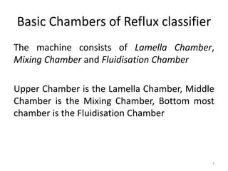


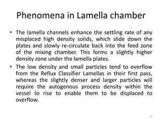


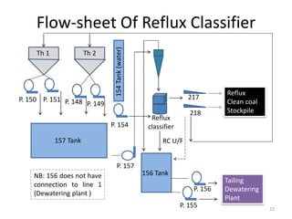


This document provides an overview of a reflux classifier. It consists of three main chambers - a lamella chamber at the top, a mixing chamber in the middle, and a fluidization chamber at the bottom. Feed material enters the mixing chamber where a fluidization process separates lighter and heavier particles based on density and size. Lighter particles overflow to the lamella chamber, while heavier particles sink to the underflow. The lamella chamber further separates particles using arrays of inclined plates. Finer particles overflow while coarser particles recirculate for additional separation. The fluidization chamber collects undersize material and controls discharge.


