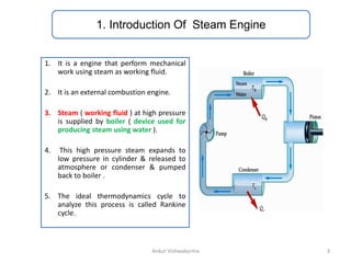
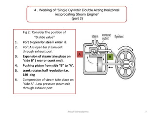
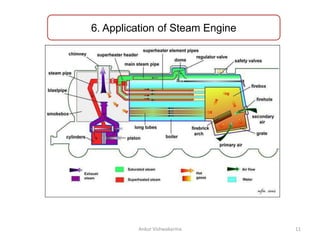
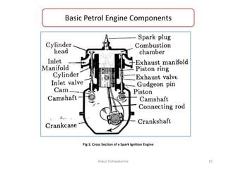
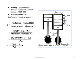
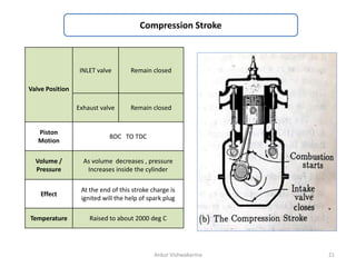
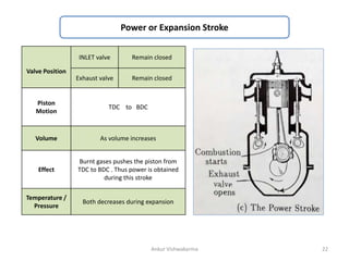
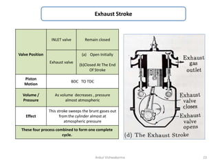
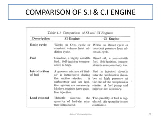
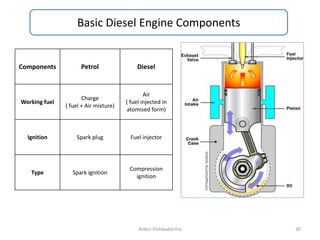
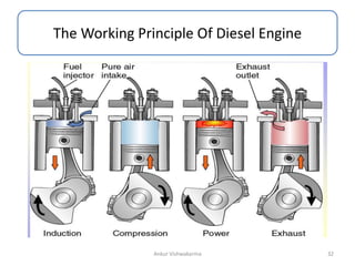
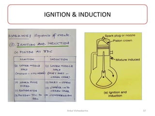
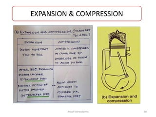
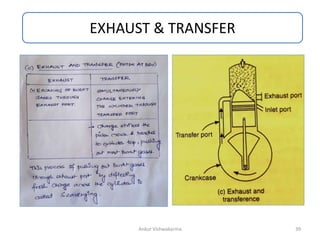
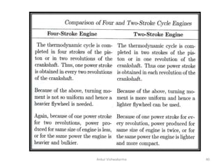
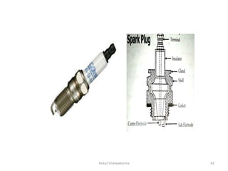
By
Ankur Vishwakarma
Department Of Mechanical Engineering
1
Reciprocating Machines
Ankur Vishwakarma
CONTENT
1. Introduction of Steam Engine
2. Classification of Steam Engine
3. Construction of “Single Cylinder Double Acting horizontal
reciprocating Steam Engine”
4. Working of “Single Cylinder Double Acting horizontal
reciprocating Steam Engine”
5. Rankine Cycle ( P-V Dig for steam engine)
6. Application of Steam Engine
2
Ankur Vishwakarma
1. Introduction Of Steam Engine
1. It is a engine that perform mechanical
work using steam as working fluid.
2. It is an external combustion engine.
3. Steam ( working fluid ) at high pressure
is supplied by boiler ( device used for
producing steam using water ).
4. This high pressure steam expands to
low pressure in cylinder & released to
atmosphere or condenser & pumped
back to boiler .
5. The ideal thermodynamics cycle to
analyze this process is called Rankine
cycle.
3
Ankur Vishwakarma
2. Classification of Steam Engine
Ankur Vishwakarma 4
3. Construction Of “Single Cylinder Double Acting
Horizontal Reciprocating Steam Engine”
5
Ankur Vishwakarma
4. Working of “Single Cylinder Double Acting horizontal
reciprocating Steam Engine”
(part 1)
Fig 1 . Consider the position of
“D slide value”
1. Port A open for steam enter &
2. Port B is open for steam exit
through exhaust port
3. Expansion of steam take place
on “side A” (Front or cylinder
head end)
4. Causing piston to move from
side “A” to “B”.
5. Crank rotates half revolution
i.e. 180 deg
6. Compression of steam take
place on “side B” . Low pressure
steam exit through exhaust port
A
B
6
Ankur Vishwakarma
4 . Working of “Single Cylinder Double Acting horizontal
reciprocating Steam Engine”
(part 2)
Fig 2 . Consider the position of
“D slide value”
1. Port B open for steam enter &
2. Port A is open for steam exit
through exhaust port
3. Expansion of steam take place on
“side B” ( rear or crank end).
4. Pushing piston from side “B” to “A”.
5. crank rotates half revolution i.e.
180 deg
6. Compression of steam take place on
“side A” . Low pressure steam exit
through exhaust port
A B
B
7
Ankur Vishwakarma
Steam flow path
8
Ankur Vishwakarma
5. Rankine cycle
( P-V Diagram for steam Engine)
9
Ankur Vishwakarma
10
Ankur Vishwakarma
6. Application of Steam Engine
11
Ankur Vishwakarma
Petrol (Otto) Engine
Ankur Vishwakarma 12
CONTENT
1. Introduction Of Petrol Engine
2. Construction Of “Petrol (Otto)engine”
3. Working Of “Petrol (Otto)engine”
4. P-V Dig Petrol (Otto ) Engine
13
Ankur Vishwakarma
PREVIOUS YEARS QUESTION
( from unit 5 , BME )
S.NO. YEAR QUESTION
1 2019
2 2018
14
Ankur Vishwakarma
Basic Petrol Engine Components
Ankur Vishwakarma 15
Fig 1: Cross Section of a Spark Ignition Engine
Nomenclature
Ankur Vishwakarma 16
Ankur Vishwakarma 17
• Stroke (L) : piston motion
between two successive dead
centres ( TDC & BDC)
• Compression Ratio (r) :
total volume / clearance volume
Ankur Vishwakarma 18
WORKING PRINCIPLE ( PETROL ENGINE )
Ankur Vishwakarma 19
Valve Position
INLET valve
(a) Open Initially
(b)Closed At The End
Of Stroke
Exhaust valve Remain closed
Piston
Motion
TDC ( top dead centre ) to
BDC ( bottom dead centre)
Volume /
Pressure
As volume Increases , pressure
decreases inside the cylinder
Effect
The charge consisting of fuel –air
mixture is drawn into the cylinder
Crank Rotation 180 ( half revolution)
Ankur Vishwakarma 20
Suction or Intake Stroke
Compression Stroke
Valve Position
INLET valve Remain closed
Exhaust valve Remain closed
Piston
Motion
BDC TO TDC
Volume /
Pressure
As volume decreases , pressure
Increases inside the cylinder
Effect
At the end of this stroke charge is
ignited will the help of spark plug
Temperature Raised to about 2000 deg C
Ankur Vishwakarma 21
Power or Expansion Stroke
Valve Position
INLET valve Remain closed
Exhaust valve Remain closed
Piston
Motion
TDC to BDC
Volume As volume increases
Effect
Burnt gases pushes the piston from
TDC to BDC . Thus power is obtained
during this stroke
Temperature /
Pressure
Both decreases during expansion
Ankur Vishwakarma 22
Exhaust Stroke
Valve Position
INLET valve Remain closed
Exhaust valve
(a) Open Initially
(b)Closed At The End
Of Stroke
Piston
Motion
BDC TO TDC
Volume /
Pressure
As volume decreases , pressure
almost atmospheric
Effect
This stroke sweeps the brunt gases out
from the cylinder almost at
atmospheric pressure
These four process combined to form one complete
cycle.
Ankur Vishwakarma 23
Various process
Ankur Vishwakarma 24
Ankur Vishwakarma 25
Actual & Indicated PV Diagram
Ankur Vishwakarma 26
COMPARISON OF S.I & C.I ENGINE
Ankur Vishwakarma 27
Ankur Vishwakarma 28
Diesel Engine
Ankur Vishwakarma 29
Basic Diesel Engine Components
Ankur Vishwakarma 30
Components Petrol Diesel
Working fuel
Charge
( fuel + Air mixture)
Air
( fuel injected in
atomised form)
Ignition Spark plug Fuel injector
Type Spark ignition
Compression
ignition
Difference between Petrol & Diesel Engine Head
Ankur Vishwakarma 31
The Working Principle Of Diesel Engine
Ankur Vishwakarma 32
COMPARISON OF OTTO & DIESEL CYLCE
( p-v diagram)
PETROL ( OTTO ) CYCLE DIESEL CYCLE
Ankur Vishwakarma 33
TWO STROKE ENGINE
Ankur Vishwakarma 34
Ankur Vishwakarma 35
Construction ( Two Stroke Engine)
Ankur Vishwakarma 36
IGNITION & INDUCTION
Ankur Vishwakarma 37
EXPANSION & COMPRESSION
Ankur Vishwakarma 38
EXHAUST & TRANSFER
Ankur Vishwakarma 39
Ankur Vishwakarma 40
Ankur Vishwakarma 41
Ankur Vishwakarma 42
Ankur Vishwakarma 43

Reciprocating Machines (ss).pptx

  • 1.
    By Ankur Vishwakarma Department OfMechanical Engineering 1 Reciprocating Machines Ankur Vishwakarma
  • 2.
    CONTENT 1. Introduction ofSteam Engine 2. Classification of Steam Engine 3. Construction of “Single Cylinder Double Acting horizontal reciprocating Steam Engine” 4. Working of “Single Cylinder Double Acting horizontal reciprocating Steam Engine” 5. Rankine Cycle ( P-V Dig for steam engine) 6. Application of Steam Engine 2 Ankur Vishwakarma
  • 3.
    1. Introduction OfSteam Engine 1. It is a engine that perform mechanical work using steam as working fluid. 2. It is an external combustion engine. 3. Steam ( working fluid ) at high pressure is supplied by boiler ( device used for producing steam using water ). 4. This high pressure steam expands to low pressure in cylinder & released to atmosphere or condenser & pumped back to boiler . 5. The ideal thermodynamics cycle to analyze this process is called Rankine cycle. 3 Ankur Vishwakarma
  • 4.
    2. Classification ofSteam Engine Ankur Vishwakarma 4
  • 5.
    3. Construction Of“Single Cylinder Double Acting Horizontal Reciprocating Steam Engine” 5 Ankur Vishwakarma
  • 6.
    4. Working of“Single Cylinder Double Acting horizontal reciprocating Steam Engine” (part 1) Fig 1 . Consider the position of “D slide value” 1. Port A open for steam enter & 2. Port B is open for steam exit through exhaust port 3. Expansion of steam take place on “side A” (Front or cylinder head end) 4. Causing piston to move from side “A” to “B”. 5. Crank rotates half revolution i.e. 180 deg 6. Compression of steam take place on “side B” . Low pressure steam exit through exhaust port A B 6 Ankur Vishwakarma
  • 7.
    4 . Workingof “Single Cylinder Double Acting horizontal reciprocating Steam Engine” (part 2) Fig 2 . Consider the position of “D slide value” 1. Port B open for steam enter & 2. Port A is open for steam exit through exhaust port 3. Expansion of steam take place on “side B” ( rear or crank end). 4. Pushing piston from side “B” to “A”. 5. crank rotates half revolution i.e. 180 deg 6. Compression of steam take place on “side A” . Low pressure steam exit through exhaust port A B B 7 Ankur Vishwakarma
  • 8.
  • 9.
    5. Rankine cycle (P-V Diagram for steam Engine) 9 Ankur Vishwakarma
  • 10.
  • 11.
    6. Application ofSteam Engine 11 Ankur Vishwakarma
  • 12.
  • 13.
    CONTENT 1. Introduction OfPetrol Engine 2. Construction Of “Petrol (Otto)engine” 3. Working Of “Petrol (Otto)engine” 4. P-V Dig Petrol (Otto ) Engine 13 Ankur Vishwakarma
  • 14.
    PREVIOUS YEARS QUESTION (from unit 5 , BME ) S.NO. YEAR QUESTION 1 2019 2 2018 14 Ankur Vishwakarma
  • 15.
    Basic Petrol EngineComponents Ankur Vishwakarma 15 Fig 1: Cross Section of a Spark Ignition Engine
  • 16.
  • 17.
  • 18.
    • Stroke (L): piston motion between two successive dead centres ( TDC & BDC) • Compression Ratio (r) : total volume / clearance volume Ankur Vishwakarma 18
  • 19.
    WORKING PRINCIPLE (PETROL ENGINE ) Ankur Vishwakarma 19
  • 20.
    Valve Position INLET valve (a)Open Initially (b)Closed At The End Of Stroke Exhaust valve Remain closed Piston Motion TDC ( top dead centre ) to BDC ( bottom dead centre) Volume / Pressure As volume Increases , pressure decreases inside the cylinder Effect The charge consisting of fuel –air mixture is drawn into the cylinder Crank Rotation 180 ( half revolution) Ankur Vishwakarma 20 Suction or Intake Stroke
  • 21.
    Compression Stroke Valve Position INLETvalve Remain closed Exhaust valve Remain closed Piston Motion BDC TO TDC Volume / Pressure As volume decreases , pressure Increases inside the cylinder Effect At the end of this stroke charge is ignited will the help of spark plug Temperature Raised to about 2000 deg C Ankur Vishwakarma 21
  • 22.
    Power or ExpansionStroke Valve Position INLET valve Remain closed Exhaust valve Remain closed Piston Motion TDC to BDC Volume As volume increases Effect Burnt gases pushes the piston from TDC to BDC . Thus power is obtained during this stroke Temperature / Pressure Both decreases during expansion Ankur Vishwakarma 22
  • 23.
    Exhaust Stroke Valve Position INLETvalve Remain closed Exhaust valve (a) Open Initially (b)Closed At The End Of Stroke Piston Motion BDC TO TDC Volume / Pressure As volume decreases , pressure almost atmospheric Effect This stroke sweeps the brunt gases out from the cylinder almost at atmospheric pressure These four process combined to form one complete cycle. Ankur Vishwakarma 23
  • 24.
  • 25.
  • 26.
    Actual & IndicatedPV Diagram Ankur Vishwakarma 26
  • 27.
    COMPARISON OF S.I& C.I ENGINE Ankur Vishwakarma 27
  • 28.
  • 29.
  • 30.
    Basic Diesel EngineComponents Ankur Vishwakarma 30 Components Petrol Diesel Working fuel Charge ( fuel + Air mixture) Air ( fuel injected in atomised form) Ignition Spark plug Fuel injector Type Spark ignition Compression ignition
  • 31.
    Difference between Petrol& Diesel Engine Head Ankur Vishwakarma 31
  • 32.
    The Working PrincipleOf Diesel Engine Ankur Vishwakarma 32
  • 33.
    COMPARISON OF OTTO& DIESEL CYLCE ( p-v diagram) PETROL ( OTTO ) CYCLE DIESEL CYCLE Ankur Vishwakarma 33
  • 34.
  • 35.
  • 36.
    Construction ( TwoStroke Engine) Ankur Vishwakarma 36
  • 37.
  • 38.
  • 39.
  • 40.
  • 41.
  • 42.
  • 43.