The document discusses key concepts of the black oil model used to describe reservoir fluids.
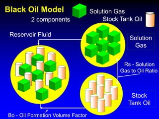
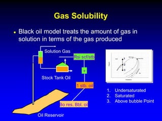
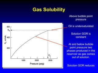
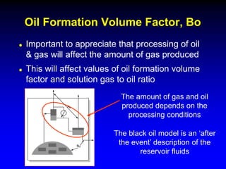
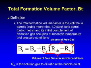
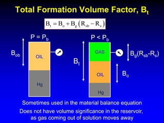
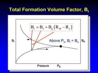
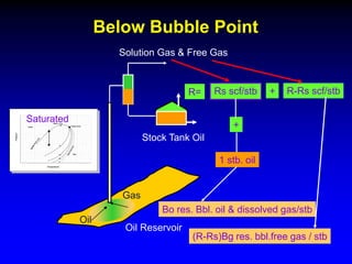
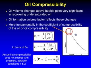
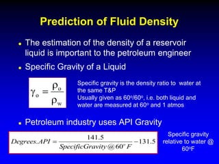
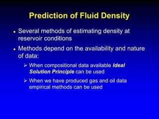
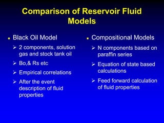
The black oil model treats reservoir fluids as having two components - solution gas dissolved in stock tank oil. It ignores compositional changes in gas with changing pressure and temperature. The model is used to predict properties like gas solubility, oil formation volume factor, and fluid density which are important for reservoir evaluation.
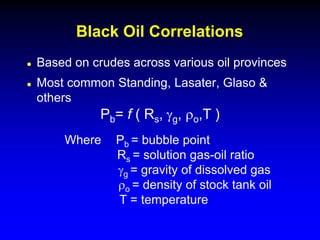
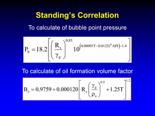
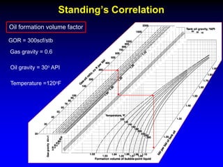
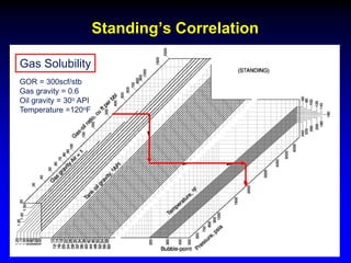
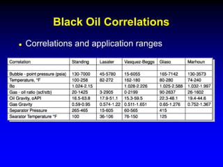
Correlations are commonly used to relate black oil parameters like gas solubility and oil formation volume factor to variables like temperature, pressure, oil and gas specific gravity. The black oil model provides a simplified approach that has been used for decades in many petroleum engineering calculations despite some limitations.