The document is a solution manual for the third edition of 'Radiative Heat Transfer' by Michael F. Modest, intended for use in graduate courses. It contains solutions for problems from various chapters, emphasizing that some chapters are more complete than others, and provides access to additional resources like Fortran90 codes. The manual is periodically updated, with a structured format to enable easy navigation through problems and solutions.


![8 RADIATIVE HEAT TRANSFER
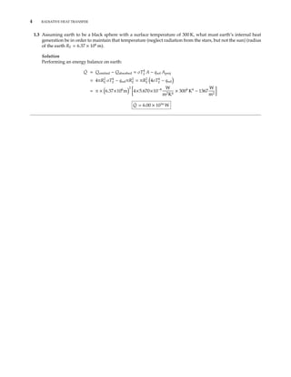
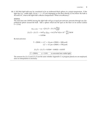
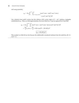
1.7 A black sphere of very high conductivity (i.e., isothermal) is orbiting earth. What is its temperature? (Consider
the sun but neglect radiation from the earth and the stars). What would be the temperature of the sphere if
it were coated with a material that behaves like a black body for wavelengths between 0.4 µm and 3 µm, but
does not absorb and emit at other wavelengths?
Solution
Making an energy balance on the sphere
(a)
Qabsorbed = Qemitted
Qabsorbed = qsolAproj = qsolπR2
Qemitted = σT4
A = σT4
4πR2
Thus
T =
qsol
4σ
1/4
=
1367 W/m2
4×5.670×10−8 W/m2
K4
1/4
T = 279 K = 6◦
C
(b) If absorption and emission takes place only over the wavelength interval 0.4 µm < λ < 3 µm, both Qabs
and Qem will be reduced. Since the sphere is spectrally black, we have
Qem = 4πR2
3 µm
0.4 µm
Ebλ dλ = 4πR2
σT4
f(3 µm×T) − f(0.4 µm×T)
Solar emission is black, i.e., qsol ∝ Ebλ(Tsun), or
qsol,λ
qsol
=
Ebλ(Tsun)
σT4
sun
,
and
Qabs = πR2
3 µm
0.4 µm
qsol,λ dλ = πR2 qsol
σT4
sun
3 µm
0.4 µm
Ebλ(Tsun) dλ
= πR2
qsol f(3 µm×Tsun) − f(0.4 µm×Tsun)
Thus,
4σT4
f(3 µm T) − f(0.4 µm T) = qsol f(3 µm Tsun) − f(0.4 µm Tsun)
= 1367 W/m2
f(17, 331) − f(2311)
T4
f(3 µmT) − f(0.4 µmT) =
1367
4×5.670×10−8
(0.9788−0.1222)
= 5.1630 × 10⁹
K4
This nonlinear relation must be solved by iteration, leading to T 600 K (< 601 K)
6004
× [0.03934 − 0] = 5.0985 × 10⁹
T = 600 K](https://image.slidesharecdn.com/radiative-heat-transfer-3rd-edition-modest-solutions-manual-190421135417/85/Radiative-Heat-Transfer-3rd-Edition-Modest-Solutions-Manual-16-320.jpg)
![10 RADIATIVE HEAT TRANSFER
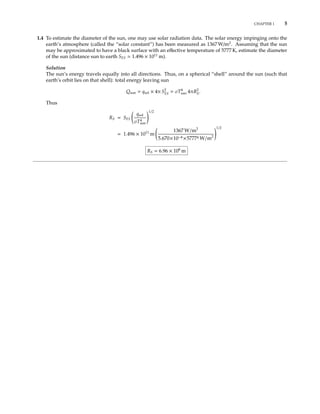
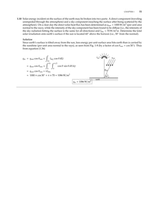
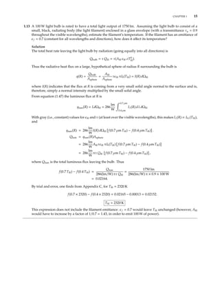
1.9 When a metallic surface is irradiated with a highly concentrated laser beam, a plume of plasma (i.e., a gas
consisting of ions and free electrons) is formed above the surface that absorbs the laser’s energy, often blocking
it from reaching the surface. Assume that a plasma of 1 cm diameter is located 1 cm above the surface, and
that the plasma behaves like a blackbody at 20,000 K. Based on these assumptions calculate the radiative heat
flux and the total radiation pressure on the metal directly under the center of the plasma.
Solution
Radiation emitted from the plasma (≈ black disk) hits the spot below it generating an incoming radiative heat
flux and a radiative pressure. From equation (1.36), for a black source
qin =
2π
Ib cos θ dΩ
1cm
1cm
plasma
θ
θmax= Ib
Ω plasma
cos θ dΩ
= 2π Ib
θmax
0
cos θ sin θ dθ
= Eb sin2
θmax = Eb ×
1
5
=
5.670 × 10−8
× 20, 0004
W/m2
5
qin = 1.814 × 10⁹
W/m2
= 181.4 kW/cm2
This should be compared to the maximum flux at the center of an unobstructed laser beam, which may be
several MW/cm2
.
The radiation pressure is found similarly, from equation (1.42) as
p =
2πIb
c
θmax
0
cos2
θ sin θ dθ =
2Eb
3c
1 − cos2
θmax =
2Eb
3c
1 −
4
5
3/2
=
2
3
5.670×10⁻⁸
20, 0004
W/m2
3 × 10⁸ m/s
[1 − 0.7155] = 5.735
Ws
m3
= 5.735
N
m2
p = 5.735 N/m2](https://image.slidesharecdn.com/radiative-heat-transfer-3rd-edition-modest-solutions-manual-190421135417/85/Radiative-Heat-Transfer-3rd-Edition-Modest-Solutions-Manual-18-320.jpg)
![CHAPTER 1 17
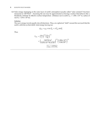
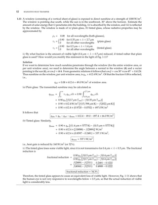
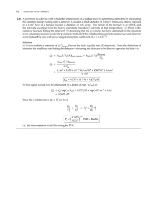
1.15 Consider a pyrometer, which also has a detector area of 1mm × 1mm, which is black in the wavelength range
1.0 µm ≤ λ ≤ 1.2 µm, and perfectly reflecting elsewhere. In front of the detector is a focussing lens (f = 10 cm)
of diameter D = 2 cm, and transmissivity of τl = 0.9 (around 1µm). In order to measure the temperature
inside a furnace, the pyrometer is focussed onto a hot black surface inside the furnace, a distance of 1 m away
from the lens.
(a) How large a spot on the furnace wall does the detector see? (Remember that geometric optics dictates
1
f
=
1
u
+
1
v
; M =
h (detector size)
H spot size
=
v
u
,
where u = 1m is the distance from lens to furnace wall, and v is the distance from lens to detector.)
(b) If the temperature of the furnace wall is 1200 K, how much energy is absorbed by the detector per unit
time?
(c) It turns out the furnace wall is not really black, but has an emittance of = 0.7 (around 1µm). Assuming
there is no radiation reflected from the furnace surface reaching the detector, what is the true surface
temperature for the pyrometer reading of case (b)?
(d) To measure higher temperatures pyrometers are outfitted with filters. If a τf = 0.7 filter is placed in front
of the lens, what furnace temperature would provide the same pyrometer reading as case (b)?
Solution
(a) From geometric optics
1
v
=
1
f
−
1
u
=
1
10cm
−
1
100cm
=
9
100cm
; v = 11.1cm
H = h
u
v
= 1mm ×
100
11.1
= 9mm.
Thus, the spot seen by the pyrometer is 9mm × 9mm in size.
(b) Energy leaving spot, intercepted by detector (or, by conservation of energy, energy intercepted by detector,
coming from spot) is
Qd = Ib12(T)AHΩHlτl = Id12AhΩhl,
where Ib12(T) =
λ2
λ1
Ibλ(T)dλ is emitted intensity from the spot on the furnace wall, Id12 is intensity absorbed
by the detector, and ΩHl and Ωhl are the solid angles with which the lens is seen from H and h, respectively.
Since H and h are small compared to f and D = 2R, we simply evaluate the solid angles from the center of
spot H and detector h:
ΩHl
πR2
u2
; Ωhl =
πR2
v2
,
and
AHΩhl = πR2 H
u
2
= πR2 h
v
2
= AhΩhl = π1cm2 .9
100
2
= 2.545 × 10⁻⁴
cm2
Therefore, Ib12(T)τl = Id12, i.e., intensity hitting detector is the same as emitted from furnace, except for the
attenuation through the lens: total energy is concentrated on a smaller spot by increasing the solid angle.
Finally,
Ib12 =
σT4
π
[f(λ2T) − f(λ1T)] =
5.67 × 10−8
× 12004
π
W
m2
[f(1440)
0.00961
− f(1200)
0.00213
]
= 280
W
m2
Ibλ(1.1µm, 1200k)∆λ = (Ebλ/T5
)(T5
/π)∆λ = 1.7228 × 10−12
×
12005
π
0.2
W
m2
= 273
W
m2](https://image.slidesharecdn.com/radiative-heat-transfer-3rd-edition-modest-solutions-manual-190421135417/85/Radiative-Heat-Transfer-3rd-Edition-Modest-Solutions-Manual-25-320.jpg)
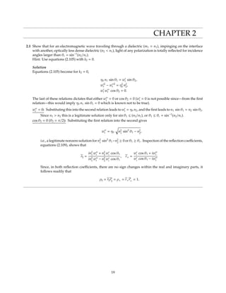
![18 RADIATIVE HEAT TRANSFER
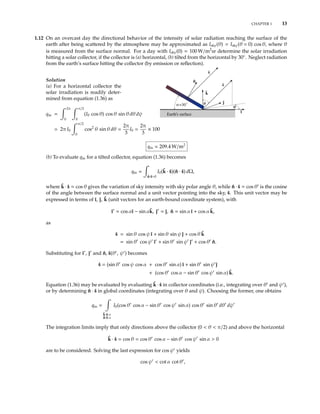
and
Qd = 280
W
m2
2.545 × 10⁻⁸
m2
× 0.9 = 6.41µW
(c) The energy hitting detector remains the same and, therefore, so does the intensity emitted from the spot:
Ib12(Ta)(actual) = Ib12(Tp = 1200K)(perceived)
or, if we assume the blackbody intensity over the detector range can be approximated by the value at 1.1µm,
eC2/λTa − 1
1
eC2/λTp − 1
,
leading to
Ta =
C2
λ
ln{1 + [eC2/λTp
− 1]}
=
14, 388µmK
1.1µm
ln{1 + 0.7[e14,388/1.1×1200
− 1]}
or
Ta = 1241K .
At these wavelengths Wien’s law holds almost exactly, i.e., we may drop the two “1”s from the above equation,
and
Ta
C2
λ
ln( eC2/λTp
) =
C2/λ
C2
λTp
+ ln
=
Tp
1 +
λTp
C2
ln
which again leads to 1241k.
(d) Similar to (c) we get τf Ib12(Ta) = Ib12(Tp) and, since τf = (c), the answer is the same, i.e,
Ta = 1241K .
Thus, a much stronger filter is needed to really extend the pyrometer’s range.](https://image.slidesharecdn.com/radiative-heat-transfer-3rd-edition-modest-solutions-manual-190421135417/85/Radiative-Heat-Transfer-3rd-Edition-Modest-Solutions-Manual-26-320.jpg)
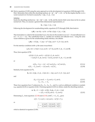
![CHAPTER 2 21
Now, eliminating Ets from equations (2.2-A) and (2.2-C) [multiplying equation (2.2-C) by iwt and adding]:
wi (Ei − Er ) + iwt cos θ1(Ei + Er ) = wtEt . (2.2-F)
Eliminating Ets from equations (2.2-C) and (2.2-E) leads to
Ets =
−iwt Et sin θ2
wt − iwt cos θ2
(Ei + Er ) cos θ1 = Et
cos θ2 −
iwt sin2
θ2
wt − iwt cos θ2
= Et
wt cos θ2 − iwt
wt − iwt cos θ2
.
Using this to eliminate Et from equation (2.2-F), with r = Er /Ei , gives
wi (1 − r ) + iwt cos θ1(1 + r ) = wt cos θ1(1 + r )
wt − iwt cos θ2
wt cos θ2 − iwt
wi (wt cos θ2 − iwt )(1 − r )
= wt(wt − iwt cos θ2) − iwt (wt cos θ2 − iwt ) cos θ1(1 + r )
= η2
0 m2
2 cos θ1(1 + r ),
r =
wi
(wt cos θ2 − iwt ) − η2
0
m2
2
cos θ1
wi
(wt cos θ2 − iwt ) + η2
0
m2
2
cos θ1
,
which is the same as equation (2.109).
It is a simple matter to show that other conditions give the same result. For example, from equation (2.64)
n2
1(Ei ˆei · ˆn + Er ˆer · ˆn) = m2
2(Et ˆet · ˆn + Ets ˆs · ˆn)
or
n2
1(Ei − Er ) sin θ1 = m2
2(Et sin θ2 − Ets cos θ2), etc.](https://image.slidesharecdn.com/radiative-heat-transfer-3rd-edition-modest-solutions-manual-190421135417/85/Radiative-Heat-Transfer-3rd-Edition-Modest-Solutions-Manual-29-320.jpg)
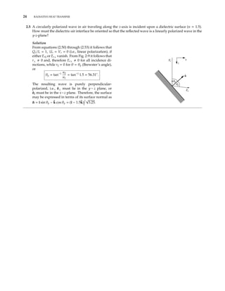
![22 RADIATIVE HEAT TRANSFER
2.3 Find the normal spectral reflectivity at the interface between two absorbing media. [Hint: Use an approach
similar to the one that led to equations (2.89) and (2.90), keeping in mind that all wave vectors will be complex,
but that the wave will be homogeneous in both media, i.e., all components of the wave vectors are colinear
with the surface normal].
Solution
Equations (2.19) and (2.20) remain valid for incident, reflected and transmitted waves, with w = w − iw =
(w −iw ) ˆn for all three cases. From equation (2.31) w·w = (w −iw )2
ˆn·ˆn = η2
0
m2
it follows that w −iw = ±η0 m.
Thus
wi − iwi = η0 m1,
wr − iwr = −η0 m1 (reflected wave is moving in a direction of − ˆn),
wt − iwt = η0 m2.
From equations (2.23) and (2.24), it follows that the electric and magnetic field vectors are normal to ˆn, i.e.,
tangential to the surface, say E0 = E0ˆt. Then, from equation (2.77)
(Ei + Er) ˆt × ˆn = Et ˆt × ˆn,
or
Ei + Er = Et
From equation (2.25) νµH0 = w × E0 = (w − iw ) E ˆn × ˆt, and from equation (2.78)
n1(Ei − Er) = m2 Et.
Substituting for Et and dividing by Ei, with r = Er/Ei:
m1(1 − r) = m2(1 + r)
or
r =
m1 − m2
m1 + m2
and
ρn = rr∗
=
(m1 − m2)(m1 − m2)∗
(m1 + m2)(m1 + m2)∗
=
(n1 − n2) + i(k1 − k2)
(n1 + n2) + i(k1 + k2)
2
ρn =
(n1 − n2)2
+ (k1 − k2)2
(n1 + n2)2 + (k1 + k2)2](https://image.slidesharecdn.com/radiative-heat-transfer-3rd-edition-modest-solutions-manual-190421135417/85/Radiative-Heat-Transfer-3rd-Edition-Modest-Solutions-Manual-30-320.jpg)
![CHAPTER 2 23
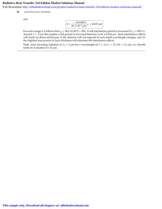
2.4 A circularly polarized wave in air is incident upon a smooth dielectric surface (n = 1.5) with a direction of
45◦
off normal. What are the normalized Stokes’ parameters before and after the reflection, and what are the
degrees of polarization?
Solution
From the definition of Stokes’ parameters the incident wave has degrees of polarization
Qi
Ii
=
Ui
Ii
= 0,
Vi
Ii
= ±1,
the sign giving the handedness of the circular polarization. With Er = Ei r and Er⊥ = Ei⊥r⊥, from equa-
tions (2.50) through (2.53):
Ir = Ei E∗
i r2
+ Ei⊥E∗
i⊥r2
⊥ = Ei E∗
i (ρ + ρ⊥) =
1
2
(ρ + ρ⊥) Ii
Since Ei E∗
i
= Ei⊥E∗
i⊥
[from equation (2.51)] and ρ = r2
.
Similarly,
Qr = Ei E∗
i r2
− Ei⊥E∗
i⊥r2
⊥ = Ei E∗
i (ρ − ρ⊥)
Ur = Ei E∗
i⊥r r⊥ + Ei⊥E∗
i r⊥r = Uir r⊥ = 0
Vr = i(Ei E∗
i⊥ − Ei⊥E∗
i ) r r⊥ = Vir r⊥
Qr
Ir
=
ρ − ρ⊥
ρ + ρ⊥
,
Vr
Ir
=
2r r⊥
ρ + ρ⊥
Vi
Ii
.
From Snell’s law
sin θ2 =
sin θ1
n2
; cos θ2 = 1 −
sin2
θ1
n2
2
= 1 −
0.5
1.52
=
7
9
,
and from equations (2.89) and (2.90)
r =
n1 cos θ2 − n2 cos θ1
n1 cos θ2 + n2 cos θ1
=
√
7/9 − 1.5
√
1/2
√
7/9 + 1.5
√
1/2
= −0.0920, ρ = 0.0085
r⊥ =
n1 cos θ1 − n2 cos θ2
n1 cos θ1 + n2 cos θ2
=
√
1/2 − 1.5
√
7/9
√
1/2 + 1.5
√
7/9
= −0.3033, ρ⊥ = 0.0920
Qr
Ir
=
0.0085 − 0.0920
0.0085 + 0.0920
= −0.8315,
Ur
Ir
= 0
Vr
Ir
= ±
2×0.0920×0.0085
0.0085 + 0.0920
= ±0.5556
Since the perpendicular polarization is much more strongly reflected, the resulting wave is no longer circularly
polarized, but to a large degree linearly polarized (in the perpendicular direction).](https://image.slidesharecdn.com/radiative-heat-transfer-3rd-edition-modest-solutions-manual-190421135417/85/Radiative-Heat-Transfer-3rd-Edition-Modest-Solutions-Manual-31-320.jpg)
![CHAPTER 2 25
2.6 A polished platinum surface is coated with a 1 µm thick layer of MgO.
(a) Determine the material’s reflectivity in the vicinity of λ = 2 µm (for platinum at 2 µm mPt = 5.29 − 6.71 i,
for MgO mMgO = 1.65 − 0.0001 i).
(b) Estimate the thickness of MgO required to reduce the average reflectivity in the vicinity of 2 µm to 0.4.
What happens to the interference effects for this case?
Solution
(a) The desired overall reflectivity must be calculated from equation (2.124) after determining the relevant
reflection coefficient. From equation (2.122)
r12 =
1 − m2
1 + m2
1 − n2
1 + n2
=
1 − 1.65
1 + 1.65
= −0.2453
since k2 1, and r12 = 0.2453. r23 may also be calculated from equation (2.122) or, more conveniently, from
equation (2.126):
r2
23 =
(1.65 − 5.29)2
+ 6.712
(1.65 + 5.29)2 + 6.712
= 0.6253 or r23 = 0.7908.
Since the real part of r12 < 0 it follows that δ12 = π, while
tan δ23 =
2(1.65×6.71 − 5.29×10⁻⁴
)
1.652 + 10−8 − (5.292 +6.712)
= −0.3150.
Since the (r23) > 0 (numerator) and (r23) < 0 (denominator) δ23 lies in the second quadrant, π/2 < δ23 < π,
or δ23 = 2.8364. Also ζ12 = 4π × 1.65 × 1 µm/2 µm = 10.3673, and
cos [δ12 ± (δ23 − ζ12)] = cos [π ± (2.8364 − 10.3673)] = −0.3175.
Also κ2d = 4π × 10−4
× 1 µm/2 µm = 2π × 10−4
and τ = e−κ2d
= 0.9994 1. Thus
R =
0.24532
+ 2×0.2453×0.7908×(−0.3175) + 0.79082
1 + 2×0.2453×0.7908×(−0.3175) + 0.24532 ×0.79082
R = 0.6149.
(b) The cos in the numerator fluctuates between −1 < cos < +1. The average value for R is obtained by
dropping the cos-term. Then
Rav =
r2
12
+ r2
23
τ2
1 + r2
12
r2
23
τ2
,
or
τ2
=
Rav − r2
12
r2
23
(1 − r2
12
)
=
0.4 − 0.24532
0.79082(1 − 0.24532)
= 0.5782,
d = −
1
κ2
ln τ = −
1
2κ2
ln τ2
=
− ln 0.5782
4π × 10−4 µm−1
= 43.6 µm.
More accurate is the averaged expression, equation (2.129)
Rav = ρ12 +
ρ23(1 − ρ12)2
τ2
1 − ρ12ρ23τ2
or
τ2
=
Rav − ρ12
ρ23 (Rav − ρ12)ρ12 + (1 − ρ12)2
=
Rav − ρ12
ρ23 1 − (2 − Rav)ρ12
=
0.4 − 0.24532
0.79082[1 − 1.6 × 0.24532]
= 0.6013](https://image.slidesharecdn.com/radiative-heat-transfer-3rd-edition-modest-solutions-manual-190421135417/85/Radiative-Heat-Transfer-3rd-Edition-Modest-Solutions-Manual-33-320.jpg)


![[Solution manual] fluid mechanics fox & mcdonald](https://cdn.slidesharecdn.com/ss_thumbnails/solutionmanualfluidmechanicsfoxmcdonaldwww-141204014630-conversion-gate02-thumbnail.jpg?width=640&height=640&fit=bounds)


