The document discusses the exploration of various 3D visualization techniques to enhance the understanding of radar characteristics, aiming for meaningful presentations. It highlights techniques for visualizing radar beam patterns, coverage, and the impact of weather conditions, as well as an ongoing study to accurately calculate power delivery. Additionally, the presentation aims to gather expert feedback to improve radar and 3D visualization approaches.
![• Useful techniques
• Fixed color map for surfaces: for easy comparison and beam consistency
• Explicitly presentation of max gain: for easy comparison
• Z axis beam propagation in logarithmic scales: for easy comparison
• Line properties also can be mapped to characteristics.
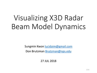
X3D visualizations using beam pattern examples from 4nec2.exe [1]
Main Lobe
Side Lobe
Side Lobe
Main Lobe
<Helical Antenna> <Spider Quad Antenna> <3-Element Yagi Antenna>
(1) Antenna Radiation Pattern
Main Lobe
[1] Arie Voors, http://www.qsl.net/4nec2/
4/15](https://image.slidesharecdn.com/radarbeamx3dvisualizationpresentation-230127180530-f4ca27e8/85/RadarBeamX3dVisualizationPresentation-pptx-4-320.jpg)

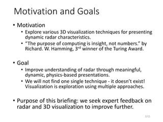
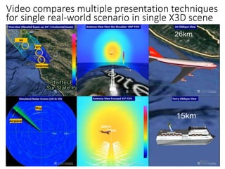
![• Weather Effects
• Thick precipitation cloud [2] to the North
• Additional parameters possible
• Objects and Radar Cross Section (RCS)
• Airplane (RCS : 1.6)
• Cruise ship (RCS : 2.2)
• Long Range Antenna
• Spanagel Hall, NPS, Monterey
• 1 revolution per 12 sec.
• 1 revolution for Cruise ship
and 1 resolution for Airplane
(2) Beam Coverage & Propagation
- Scenario for proposed techniques
[2] Yeonsoo Yang, http://examples.x3dom.org/example/RadarVolumeStyle
6/15](https://image.slidesharecdn.com/radarbeamx3dvisualizationpresentation-230127180530-f4ca27e8/85/RadarBeamX3dVisualizationPresentation-pptx-6-320.jpg)
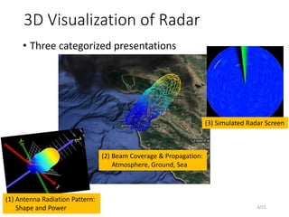
![Useful techniques
• 3D coverage envelop over the map
• To present 3D range that radar can detect
• Variant color on objects
• To present power level to be delivered
• Intuitive way to visualize power inside radar beam
• Bent radar beam
• To show effects of weather condition (attenuation
and refractive)
• Goal : Effective Visualization to show ‘how much power
is delivered to some point?’
Need more study to calculate accurate power
• Simple calculations are used to show visualization concept.
• Ongoing study using AREPS 3.0[3]
3D Coverage
[3] W.L.Patterson, “Advanced refractive effects prediction system (AREPS),” Conf. 2007 IEEE Radar, pp. 891–895, 2007.
7/15
Power](https://image.slidesharecdn.com/radarbeamx3dvisualizationpresentation-230127180530-f4ca27e8/85/RadarBeamX3dVisualizationPresentation-pptx-7-320.jpg)
![• Simulated Radar Screen
• 3D as 2D presentation
• Until now calculated by Matlab example [4].
• Need digital radar data to validate
Simulated Radar Screen
Consideration
[4] www.mathworks.com/help/phased/examples/scan-radar-using-a-uniform-rectangular-array.html
9/15](https://image.slidesharecdn.com/radarbeamx3dvisualizationpresentation-230127180530-f4ca27e8/85/RadarBeamX3dVisualizationPresentation-pptx-9-320.jpg)


![[1] 4nec2.exe Program
• NEC-2 based antenna modeler and optimizer
• Arie Voors encapsulates NEC2 code with windows-based
GUI and provides good environment to use NEC2 code.
• You can get this program free. (ver 5.8.16)
• http://www.qsl.net/4nec2/
• NEC (Numerical Electromagnetics Code)
• Popular antenna modeling system for wire and surface
antennas
• It was originally written in FORTRAN in the 1970s by
Gerald Burke and Andrew Poggio of the Lawrence
Livermore National Laboratory.
• By far the most common version is NEC-2, the last to be
released in fully public form
https://en.wikipedia.org/wiki/Numerical_Electromagnetic
s_Code
12/15](https://image.slidesharecdn.com/radarbeamx3dvisualizationpresentation-230127180530-f4ca27e8/85/RadarBeamX3dVisualizationPresentation-pptx-12-320.jpg)

![• https://examples.x3dom.org/example/RadarVolumeStyle
• with a fog of kansai_pawr_20120726175907.png
• https://dl.acm.org/citation.cfm?id=2775323
• https://vimeo.com/103145827
[2] Cloud data from Weather radar
14/15](https://image.slidesharecdn.com/radarbeamx3dvisualizationpresentation-230127180530-f4ca27e8/85/RadarBeamX3dVisualizationPresentation-pptx-14-320.jpg)
![[3] AREPS 3.0 example
• W. L. Patterson, “Advanced refractive effects prediction
system (AREPS),” Conf. 2007 IEEE Radar, pp. 891–895, 2007.
15/15](https://image.slidesharecdn.com/radarbeamx3dvisualizationpresentation-230127180530-f4ca27e8/85/RadarBeamX3dVisualizationPresentation-pptx-15-320.jpg)
![• www.mathworks.com/help/phased/examples/scan-radar-
using-a-uniform-rectangular-array.html
[4] Scan Radar Matlab Example
16/15](https://image.slidesharecdn.com/radarbeamx3dvisualizationpresentation-230127180530-f4ca27e8/85/RadarBeamX3dVisualizationPresentation-pptx-16-320.jpg)


![Antenna lecture course CHapter 2_(2)[1].pdf](https://cdn.slidesharecdn.com/ss_thumbnails/antennach221-240525095938-532f47be-thumbnail.jpg?width=640&height=640&fit=bounds)