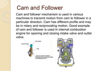
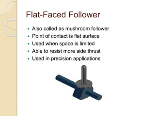
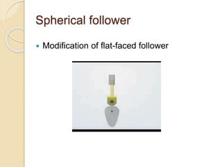
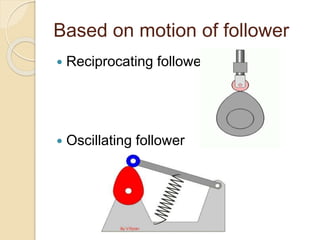
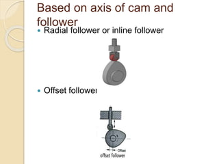
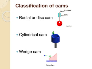
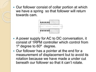
4. Theory
Cam-follower mechanism:
The slider or roller in contact with the cam that
transmits the movement dictated by the cam
profile.
Cams:
Cam is a machine element which is used in cam
and follower mechanism to transmit the rotatory
motion into linear motion with help of follower
Types of cam :
1. Radial or Disc cam
2. Cylindrical cam
3. Translation or wedge cam
4. Spherical cam
5. Cam and Follower
Cam and follower mechanism is used in various
machines to transmit motion from cam to follower in a
particular direction. Cam has different profile and may
be in rotary and reciprocating motion. Good example
of cam and follower is used in internal combustion
engine for opening and closing intake valve and outlet
valve.
6. Quick Return Mechanism
The Whitworth quick return mechanism converts
rotary motion into reciprocating motion, but unlike the
crank and slider, the forward reciprocating motion is
at a different rate than the backward stroke. This
mechanism is used in shaping machines and
presses.
7. Cams and Followers
Cam :
Cam is rotating machine element which provides
reciprocating or oscillating motion to the follower.
Follower :
Follower converts the rotary motion of cam into
reciprocating or oscillating motion.
8. Classification of followers
Based on surface of contact
All these types of followers are
reciprocating followers:
1. Knife edge follower
2. Roller follower
3. Flat-faced follower
4. Spherical follower
9. Knife Edge Follower
Here are many advantages and somehow
disadvantages of this type of follower
Point of contact is a sharp edge
Simplest follower in construction
Used for slow applications
Used in paper-cutting machines
More wear and tear
Not suitable for precision applications w.r.t time
10. Roller Follower
Motion becomes more smooth
Less amount of wear and tear
Used in precision applications
Can be operate at very high speed
11. Flat-Faced Follower
Also called as mushroom follower
Point of contact is flat surface
Used when space is limited
Able to resist more side thrust
Used in precision applications
16. How to design cam follower
apparatus?
What should be the length of follower?
What should be the max displacement by
follower?
How can we increase or decrease the
displacement of follower?
What should be the length of the lobe lift?
What a new design as compare to the
conventional cam?
18. Cam design information
Cam hole through which shaft has inserted
diameter 23mm (around which cam rotate ).
As the dia of shaft is too small. So 360º
degrees cannot be mentioned as it has a
cause it will be difficult to see as 360 lines
will be marked and they will overlap.
So we created a scale of 1 small line = 4º
degrees.
19. Our follower consist of collar portion at which
we have a spring so that follower will return
towards cam.
A power supply for AC to DC conversation, it
consist of 1RPM controller which control from
1º degree to 60º degree.
Our follower has a pointer at the end for a
measurement of displacement but to avoid its
rotation because we have made a under cut
beneath our follower so that it can’t rotate.
20. We also attached a gear motor to
develop automatic continues rotation.
Manufacturing:
We can cut the cam through CNC wire
cutting machine.
Follower and block manufacture through
casting and then machining.