Download to read offline
![Methodology and Relation to other Research Projects
The model developed in this report draws on the work carried out in various
other research projects. The terminology, methodology, and theoretical framework
are influenced by European techno-economic research projects:
TONIC, TETRA, ECOSYS and BROADWAN while the infrastructure and
technology aspects draw from BREAD, FAN and BROADWAN. More specifically
the relationship to these projects is as follows:
BREAD
Broadband in Europe for All: a multi-disciplinary approach aims at
developing a roadmap for the deployment of broadband and realisation of the
'broadband for all' concept within Europe. This report relies on the access and
backbone network overview provided in deliverable 2 [2]
TONIC
IST-2000-25172 TONIC (TechnO-EcoNomICs of IP optimised networks
and services) concentrates on techno-economic evaluation of new communication
networks and services. Following up on older projects, TONIC was carried out in
1998-2002 and provides the foundation of most theoretical and methodological
work on techno-economic studies. This project therefore provided a starting point
for development of the simulation model [11].
ECOSYS
An ongoing research project on the techno-economics of integrated
communication systems and services. The most interesting part of the ECOSYS
project for this study is the advancement and evolution of the theoretical and
methodological framework developed for techno-economic analysis of
telecommunications networks in the TONIC project. [5]
BROADWAN
The goal of the “Broadband services for everyone over fixed wireless
access networks” is to investigate how wireless networks can be used to provide
true broadband services.
6](https://image.slidesharecdn.com/qos-101227135157-phpapp02/75/Qos-WiMax-6-2048.jpg)
![The most interesting aspects of the BROADWAN project for this study is
the analysis of market potential and deployment scenarios and future development
of wireless access technologies. Additionally, the project has developed a
simulation model for deployment cost based on methods developed in the TONIC
project. [3]
FAN
EURESCOM P1117-FAN evaluates the technical specifications of future access
networks, the impact of IP and infrastructure architectures. For this report it was
used to reinforce the infrastructure and access technology selection. [6,7]
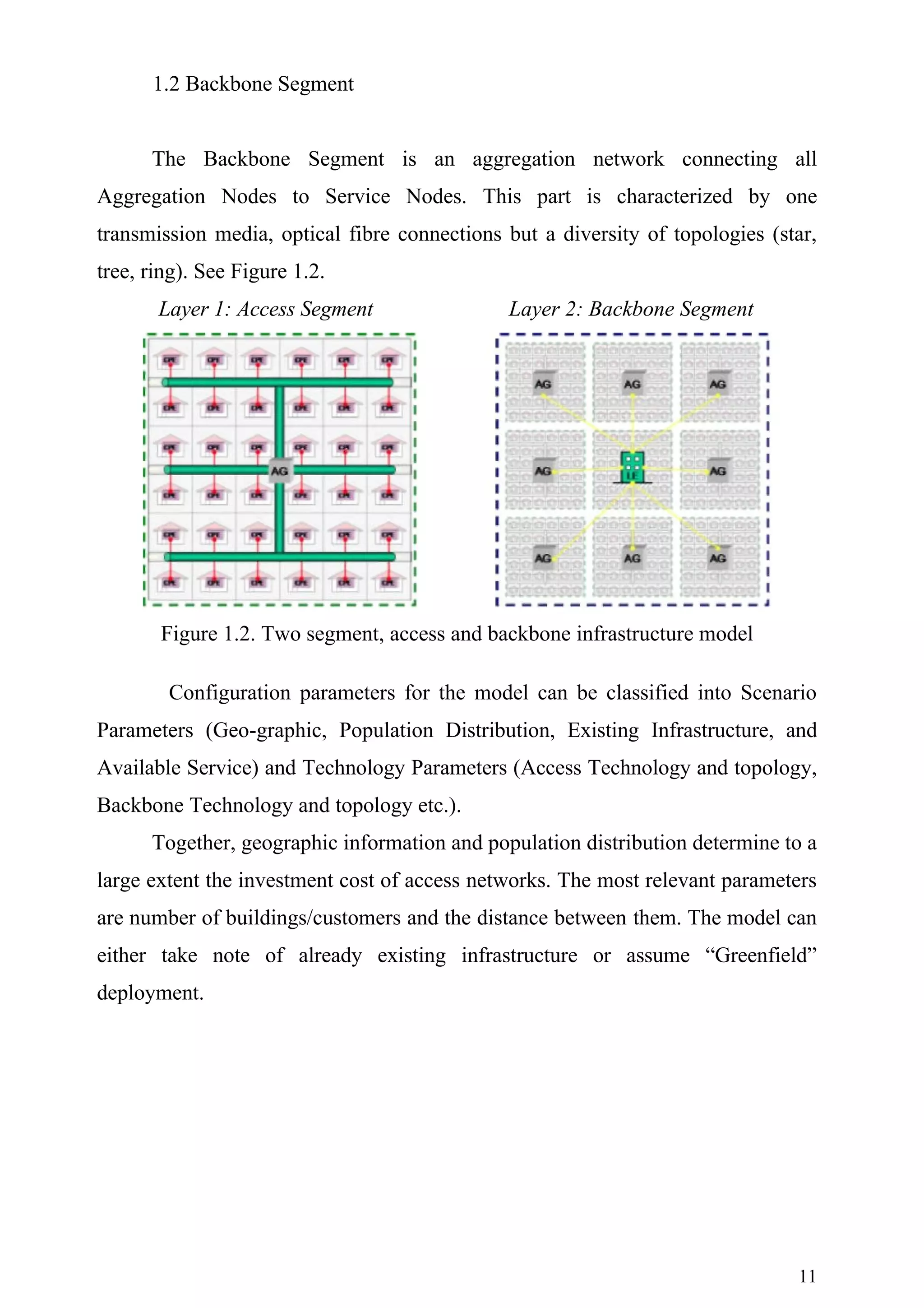
Model Structure and Functionality
The overall model structure is based on dividing the network into two
segments: Access Segment and Backbone Segment. The Access Segment covers
the so called “first mile” from user premises to an aggregation node in the
respective zone. This part is characterized by a diversity of transmission media
(copper, fibre, cable, radio), and topologies (star, tree).
Several technical solutions exist for provision of broadband to customers in
different types of demographic areas.
Research indicates that the future market will be characterised by different
coexisting technologies, the choice of which is determined by technological
capabilities as well as economic factors.
The BREAD project has on basis of results from other projects in the EU
Framework Program 6 analysed technological alternatives, future trends, and
status of broadband initiatives. Results from following European techno-economic
projects have been applied in the modelling work: BREA D, TONIC, ECOSYS,
BROADWAN and FAN. For the purpose of this report techno-economic methods
are used to analysed and compare deployment scenarios for five of the most
widely used technological alternatives. A simulation model has been developed to
examine the effect of influential factors, such as transmission speed and level of
existing infrastructure, in providing broadband connectivity in urban, suburban
and rural areas. For those technologies building on use of existing infrastructures
calculations are made both for a two different scenarios: Upgrade of existing
infrastructures and greenfield.
7](https://image.slidesharecdn.com/qos-101227135157-phpapp02/75/Qos-WiMax-7-2048.jpg)
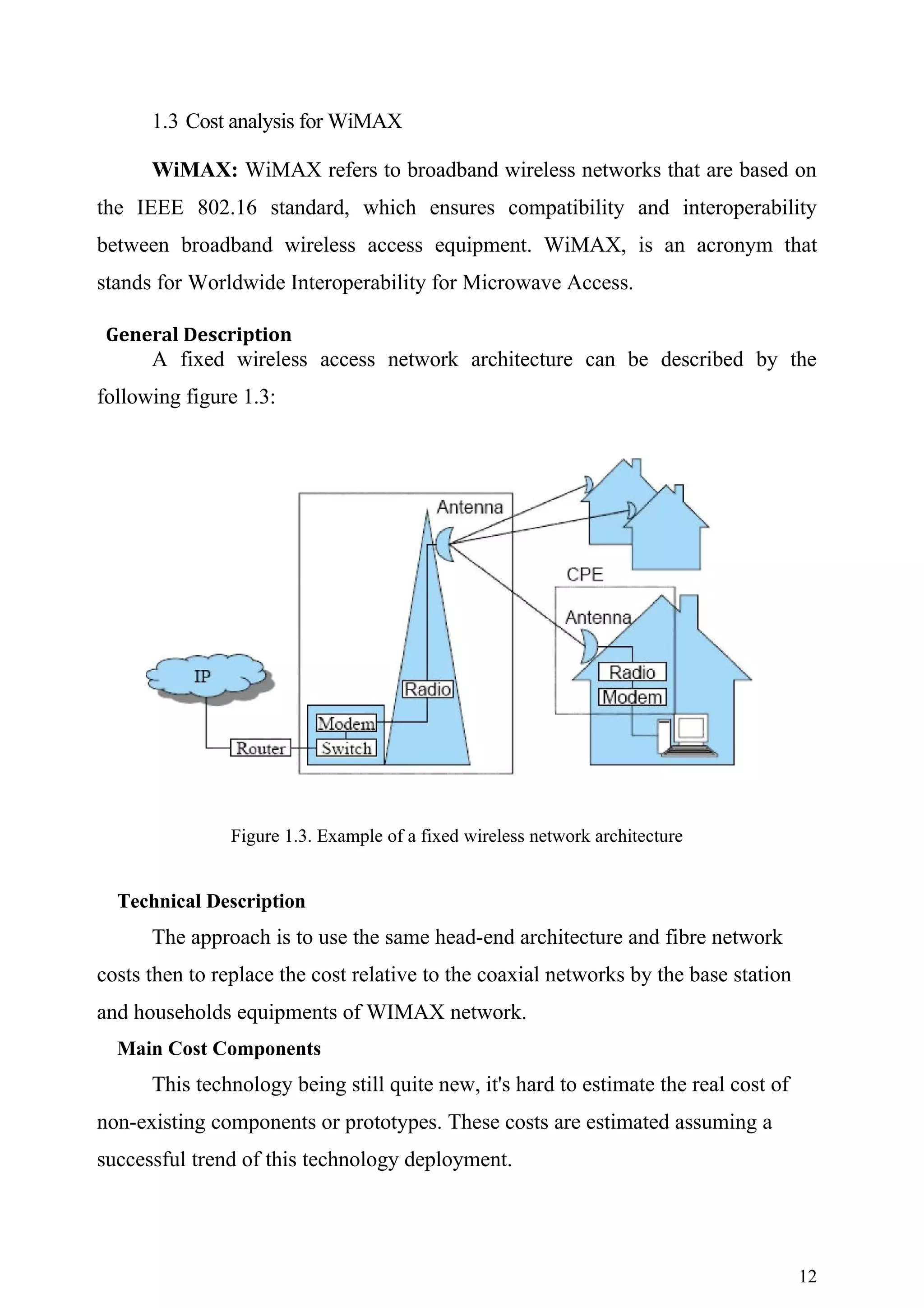
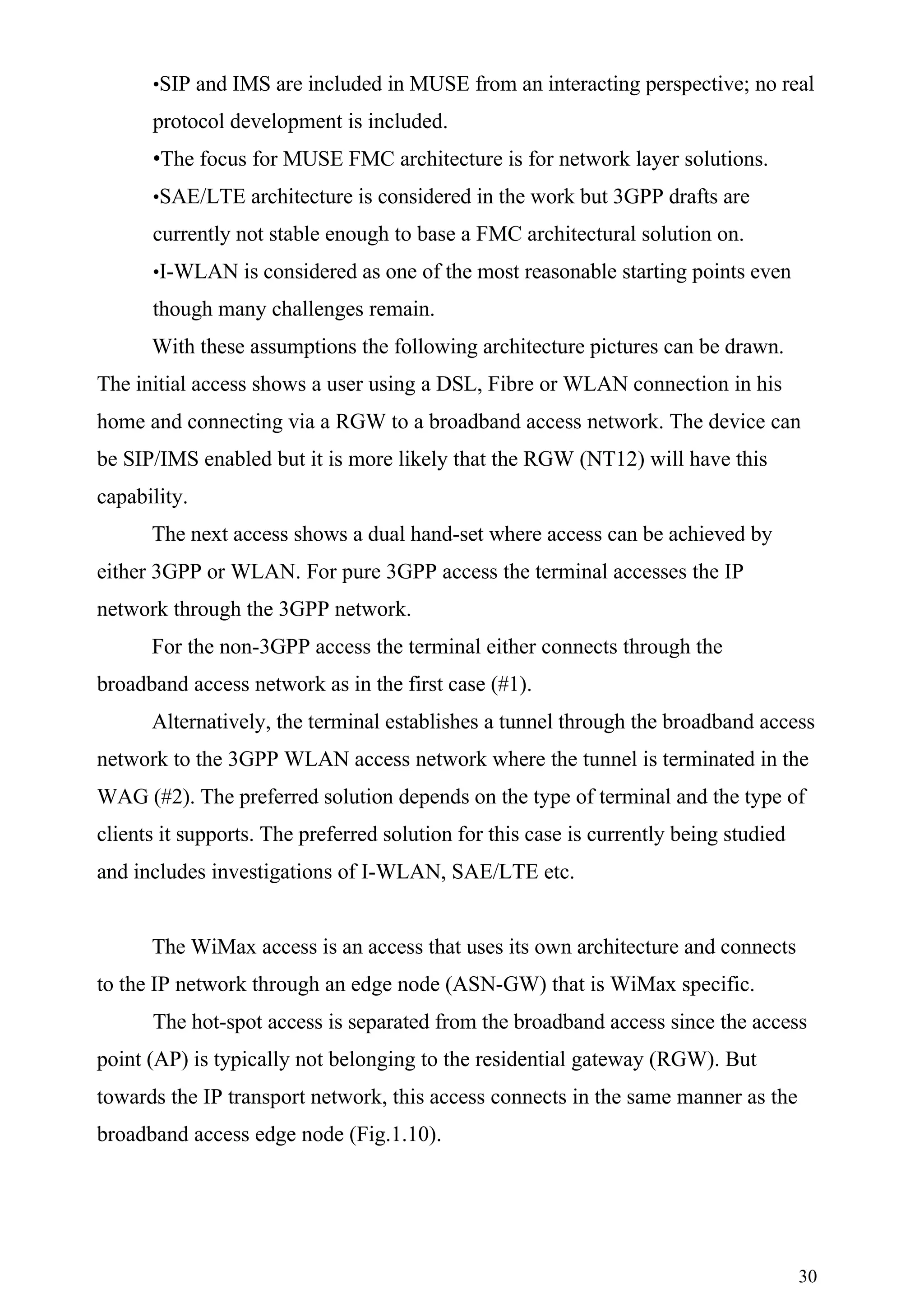
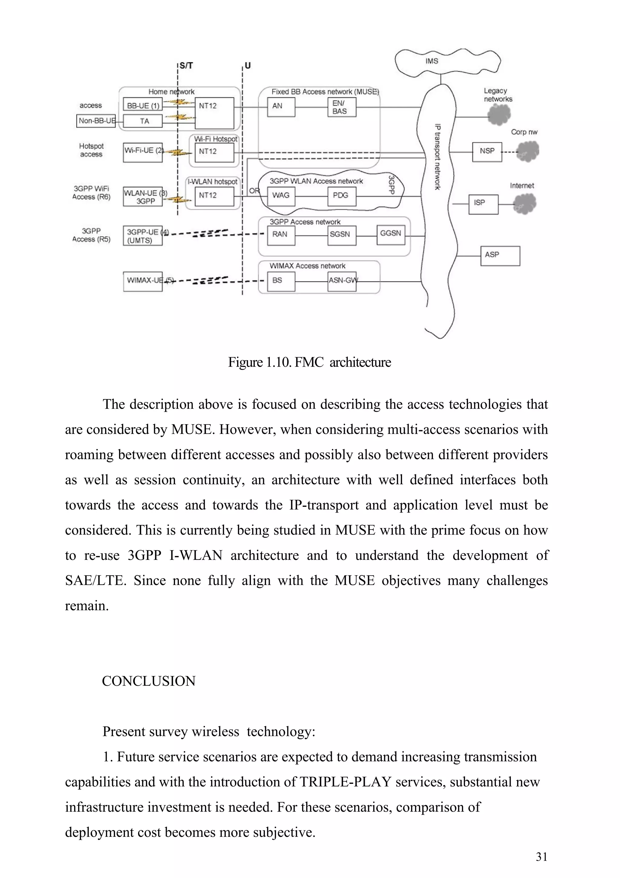
![The network architecture considered in this deliverable consists of a
heterogeneous network, which includes fixed and mobile access networks. It is in
line with the overall FMC access architecture defined in DTF1.8 [4]. As the scope
is limited to session continuity in a single operator domain, there is no need for
roaming agreement in order to support mobility within or between the different
networks. Session continuity in case of roaming was not considered because it is
an additional level of complexity. Note that also today's GSM networks generally
do not support session continuity when crossing provider domains. However, all
the technical details that are required to maintain and transfer an ongoing session
must be worked out. To begin with the user devices must have multiple types of
interface cards to be able to communicate with the different types of networks.
Before a user is allowed to connect to the fixed or the Mobile access networks she
has to be authenticated and authorized to connect and access her subscribed
services.
Figure 1.5. Reference Network architecture
17](https://image.slidesharecdn.com/qos-101227135157-phpapp02/75/Qos-WiMax-17-2048.jpg)
![business or school and this is “shared out” using a wireless network to customers
in a community.
The main WiFi standards are:
802.11a – capable of high data speeds over relatively short distances using
the 5Ghz frequency. This is good for delivering video and large amounts of data,
but the limited range means it is hard to make a case for dispersed rural areas.
802.11b – capable of 11Mb/s although in reality the throughput is closer to 5Mb/s.
Equipment is now available at relatively low cost and most new laptops have
WiFi connectivity built in as standard. It is good at covering short distances and is
popular with many WiFi operators.
802.11g – capable of 54Mb/s is capable of high data rates but can only
cover relatively short ranges compared to 802.11b.
Spectrum
These standards do not require a license in most European countries,
making them quick and easy to deploy. They mainly operate in the 5Ghz and
2.4Ghz range. For details on licensing for each EU state, check with the national
government.
Case Study
Cybermoor in the UK uses WiFi to deliver broadband to a remote rural
community. Cybermoor takes a broadband service from the school.
802.1x pre-authentication
This enhancement to 802.1X authentication is presented in [19] and is aimed
at speeding up the authentication process of a 802.11 MS by doing an
authentication with a new point of attachment before actually moving to this point
of attachment.
The main principle, as depicted in Figure 1.8, is that the serving AP is used
to communicate with the target AP via the distribution system that connects both
APs together. Hence, the MS will exchange all the authentication information
with the target AP via the serving AP. Once the authentication is done, the MS
could move to the new AP, where access would be granted for it.
23](https://image.slidesharecdn.com/qos-101227135157-phpapp02/75/Qos-WiMax-23-2048.jpg)
![Figure 1.8. 802.1X pre-authentication principle
For this scenario to be completely inline with MUSE requirements
regarding trust of RGW devices, the CAPWAP approach should be applied. As
described in [18], this approach enables the separation of the radio and the
management functions for the APs. In this situation the authenticator function of
the AP is located at the ANs. However, this fact does not change the pre-
authentication principle described above. The only difference is that the
authenticator entity for each AP is located at the AN instead of being physically
located at the AP itself. This is depicted in Figure 1.9. However, for the sake of
simplicity, the remaining text refers only to the APs as whole (regardless if the
functions are physically separated or not, the AP could still be seen one element).
Figure 1.9. Pre-authentication principle for extended APs due to the separation
proposed by CAPWAP
24](https://image.slidesharecdn.com/qos-101227135157-phpapp02/75/Qos-WiMax-24-2048.jpg)
![As described in [19], there are a number of issues related to 802.1X pre-
authentication deployment:
-The MS starts the authentication with the target AP. There should be a
mechanism through which the MS decides which is the best AP to move to.
This mechanism is not defined by the 802.1X pre-authentication and could
be based on basic signal strength measurements or on more sophisticated
mechanism as describe in [20] and [21], where a Frequent Handover Region
(FHR) is defined.
-In order to forward the 802.1X pre-authentication packets correctly to the
target AP, the BSSID of the target AP is used as its MAC. This might have
certain configuration constrains
-Another Ethertype is defined to differentiate between 802.1X pre-
authentication frames and normal 802.1x frames. This is due to the switch
traversal problem of 802.1X messages.
As stated before, the distribution system that connects the APs is used to
forward the 802.1X messages between the MS and the target AP. Hence, layer 2
connectivity between APs is required because 802.1X is encapsulated directly
over L2 frames.
For this communication to take place in the SPC platform there are two
different approaches that could be taken:
1.The first approach would be that messages between APs are forwarded
via EN. This way, the forwarding principles of the SPC platform persist.
2.Another possibility would be to configure the intermediate switches in the
aggregation network to permit inter AP communication. This mechanism
would go against the SPC forwarding principles but would still be possible
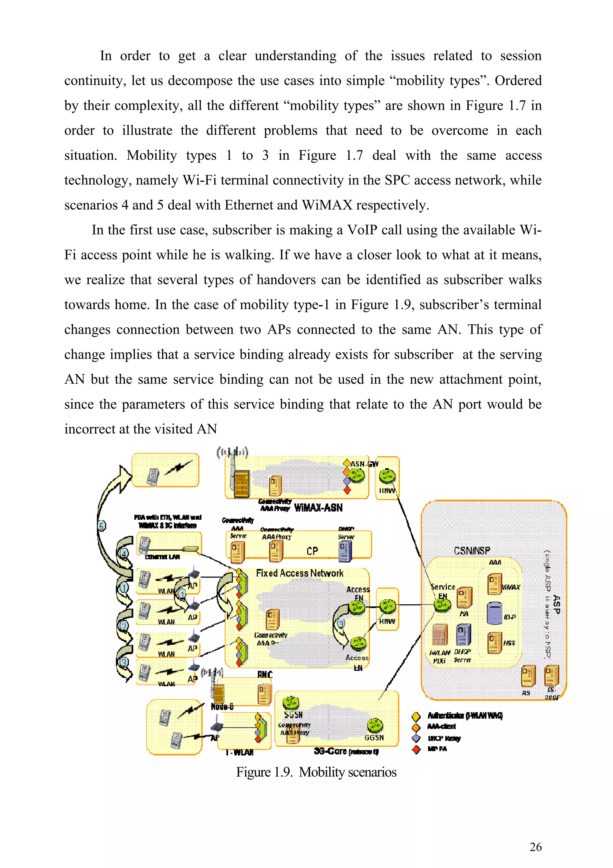
1.8 Use case analysis
As can be seen by the use cases studied in the previous section, there are
several mobility types that need to be considered.
25](https://image.slidesharecdn.com/qos-101227135157-phpapp02/75/Qos-WiMax-25-2048.jpg)
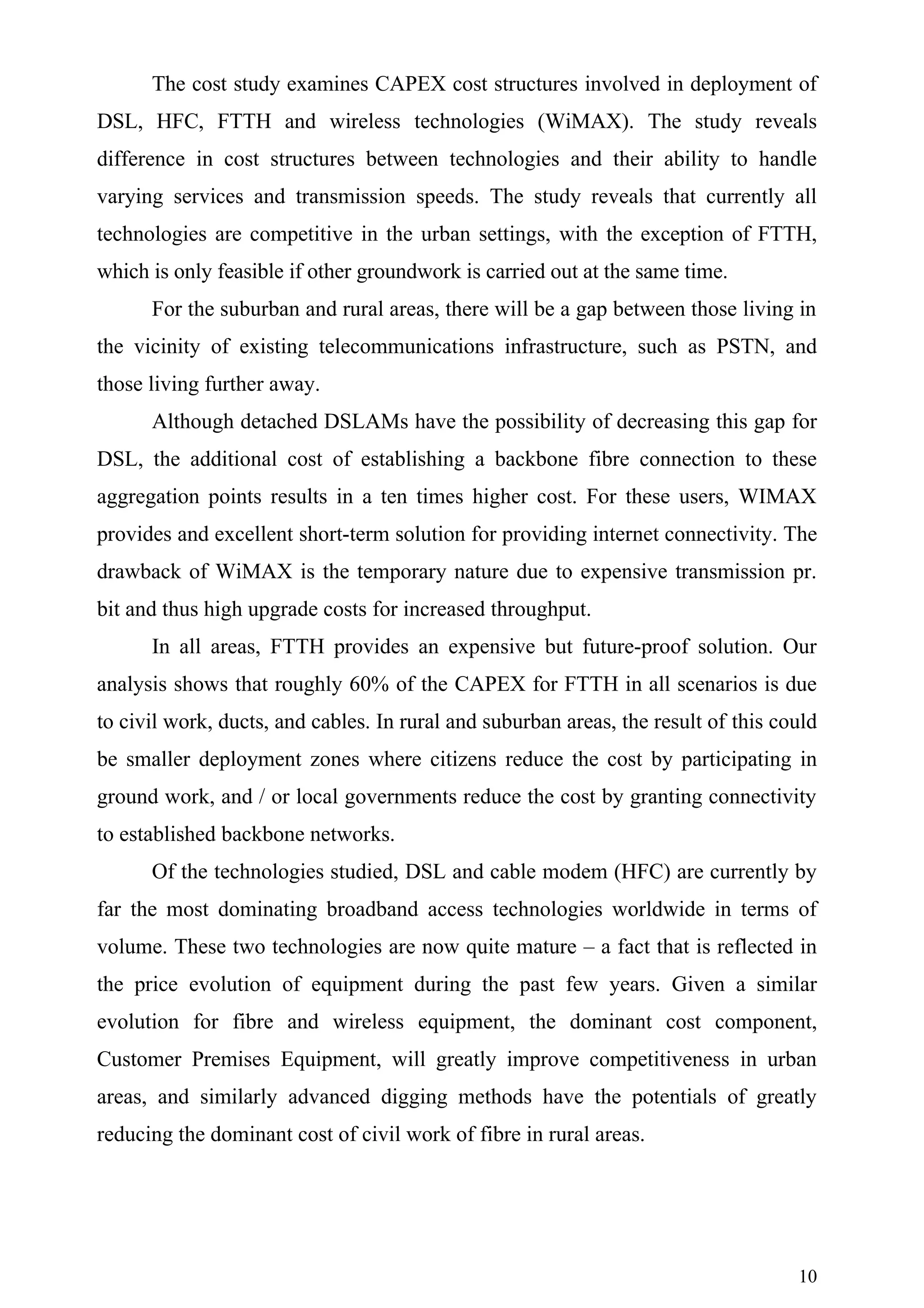
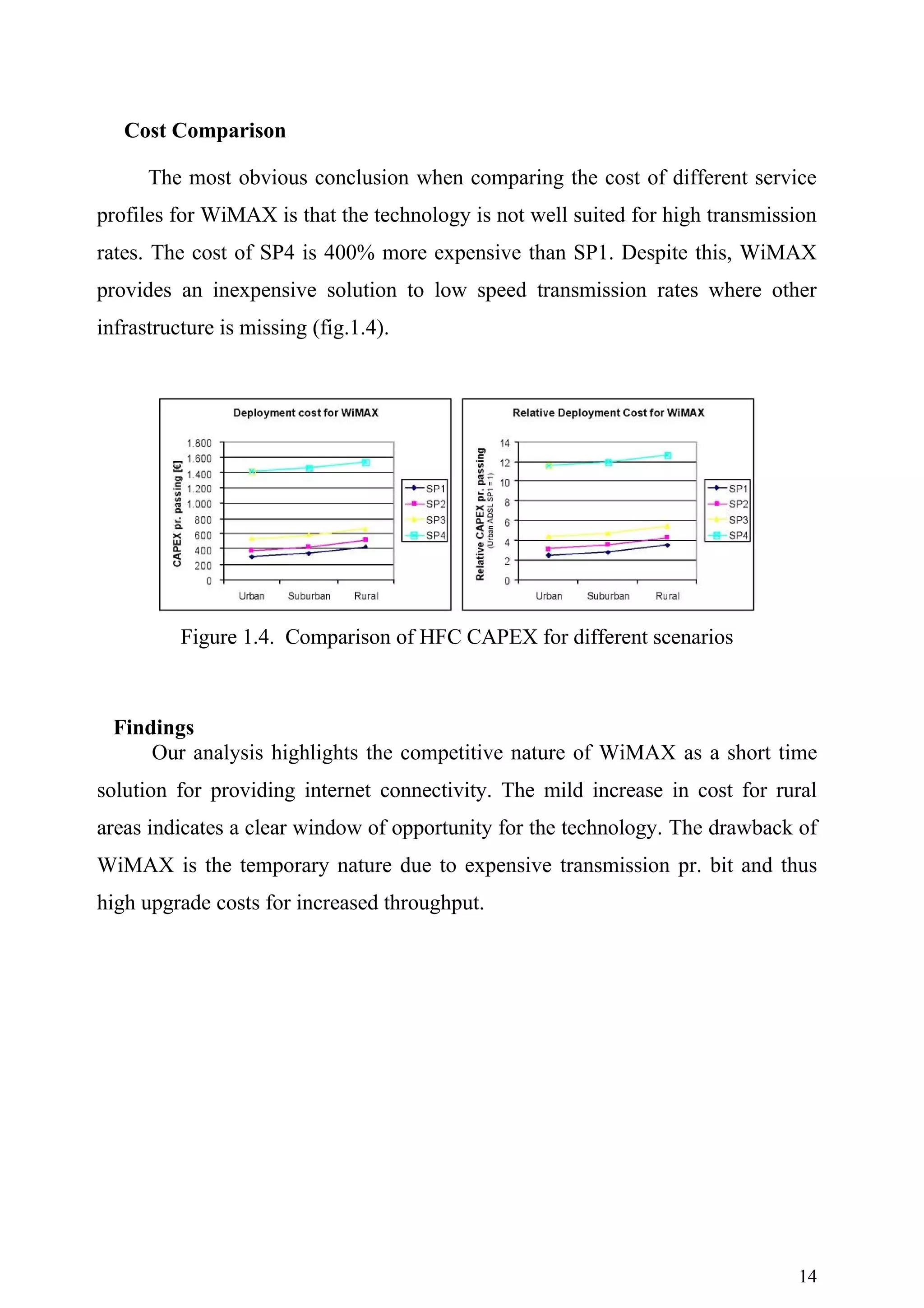
![3.The cost study examines CAPEX cost structures involved in deployment
of DSL, HFC, FTTH and wireless technologies (WiMAX). The study
technologies and their ability to handle varying services and transmission
speeds.
4.For these users, WIMAX provides and excellent short-term solution for
providing internet connectivity. The drawback of WiMAX is the temporary
nature due to expensive transmission pr. bit and thus high upgrade costs for
increased throughput.
5.Research cost structure of WiMAX and network architecture in future.
In this model, end users will be able to access their services from different
networks, and are not tied to a fixed only or mobile only type of subscription as is
the case in today’s subscription offers. In DC1.7 we have provided a solution for
the inter-working and integration of the SPC access solution and WiMAX
network.
6.Present FMC Architecture and wireless technologies WiFi. In the first
use case, subscriber is making a VoIP call using the available Wi-Fi access
point while he is walking.
Architecture for FMC is still in its early stage and many issues are still to be
resolved. However, a few working assumptions already exist and will act as the
base for the architectural development
REFERENCES
[I] BREAD (FP6-IST-507554), Deliverable 1 “First, combined, report on the multi-
technological and multi-
disciplinary analysis of the ‘broadband for all’ concept“, April 2004.
[2] BREAD (FP6-IST-507554), Deliverable 2, “Second report on the multi-technological
analysis of the
‘broadband for all’ concept, focus on the listing of multi-technological key issues and
practical roadmaps on how to tackle these issues“, August 2005.
[3] BROADWAN (FP6-2002-IST-1), Deliverable 15 “Broadband access roadmap
based on market
assessment and technical-economic analysis” , February 2005.
[4] BROADWAN (FP6-2002-IST-1), Project Web Page: http://www.telenor.no/broadwan/
[5] ECOSYS (CELTIC CP1-021), Project Web Page:
http://optcomm.di.uoa.gr/ecosys/index.html
32](https://image.slidesharecdn.com/qos-101227135157-phpapp02/75/Qos-WiMax-32-2048.jpg)
![[6] FAN (Eurescom P-1117), Deliverable 1 “IP based access technologies and QoS”, May
2003.
[7] FAN (Eurescom P-1117), Deliverable 2 “Broadband access network target architectures -
access network
evolution scenarios and strategies”, May 2003.
[8] Green P.E., “Fiber To The Home – The New Empowerment”, Wiley Interscience, N.J.,
2006
[9] Indenrigs- og Sundhedsminesteriet (e. Danish Ministry of the Interior and Health),
Statistical Database
on the Internet: http://www.noegletal.dk/, Accessed March 2006
[10] Sigurdsson H.M., “Implementing Next -Generation-Networks in Iceland”, CTI M.Sc.
Thesis, Danish Technical University, June 2003.
[II] TONIC (IST-2000-25172), Deliverable number 7 “Report on tool and methodology”,
February 2002.
[12] TONIC (IST-2000-25172), Project Web Page: http://www-nrc.nokia.com/tonic/
[I] Technical Annex MUSE Phase II
[2] DC1.5 “Network Solution to Support Nomadism in a fixed access network and
dual packager roaming in a multi operator scenario”, MUSE Phase II, deliverable,
June 2007. [3] DC1.6 “Solution to Support Nomadism and roaming in between fixed
and wireless
networks in a multi operator scenario”, MUSE Phase II, deliverable, June 2007. [4]
DTF1.8 "FMC in Fixed Access Architecture", MUSE Phase II, deliverable,
June 2007. [5] http://www.airspan.com/pdfs/WP_Mobile_WiMAX_Security.pdf [6]
Tanenbaum, A. S., “Computer Networks”, Fourth Edition, Prentice Hall, ISBN 0-13-066102-3. [7]
http://www.microsoft.com/technet/community/columns/cableguy/cg0405.mspx [8] P.
Arvidsson and M. Widell, “Design of a session layer based system for endpoint
mobility”. Master's thesis, KTH, 2006. [9] Y. Ismailov, J. Holler, S. Herborn, A.
Seneviratne, “Internet Mobility: An Approach
to Mobile End-System Design”, International Conference on Mobile
Communications and Learning Technologies, ISBN 0-7695-2552-0, IEEE
Computer Society, Los Alamitos, CA, USA, 2006. [10] Microsoft: “Performance
Enhancements in the Next Generation TCP/IP Stack”,
http://www.microsoft.com/technet/community/columns/cableguy/cg1105.mspx,
2005
[II] Microsoft: “Windows TCP/IP Registry Entries”,
http://support.microsoft.com/kb/158474, 2007
[12] R. Stewart, Q. Xie, K. Morneault, C. Sharp, H. Schwarzbauer, T. Taylor, I. Rytina,
M. Kalla, L. Zhang and V. Paxson: “Stream Control Transmission Protocol”,
Request for Comments: 2960, 2000 [13] L. Ong and J. Yoakum: “An Introduction to the
Stream Control Transmission
Protocol (SCTP)”, Request for Comments: 3286, 2002 [14] Perkins, Ed. C., IP Mobility
Support for IPv4, RFC 3344, August 2002. [15] S. Gundevelli, K. Leung, V. Devarapalli,
K.Chowhury and B. Patil: “Proxy Mobile
IPv6”, Internet Draft 2007 [16] MUSE D T1.8 – “FMC Support in Fixed Access
Architecture”, MUSE Phase II,
deliverable, June 2007 [17] Stefan Mangold, et al, “IEEE 802.11e Wireless LAN for
Quality of Service” [18] T. Clancy et al, “EAP Re-authentication Extensions”, draft-ietf-hokey-
erx-02, work
in progress, July 2007 [19] “IEEE Std 802.11i™-2004 (Amendment to IEEE Std
802.11™, 1999 Edition
(Reaff 2003))” [20] S. Pack and Y. Choi, “Fast Inter-AP Handoff using Predictive-
Authentication
Scheme in a Public WirelessLAN,” IEEE Networks 2002, August [21] S. Pack and Y.
Choi, “Pre-Authenticated Fast Handoff in a Public Wireless LAN
based on IEEE 802.1x Model,” IFIP TC6 Personal Wireless Communications
33](https://image.slidesharecdn.com/qos-101227135157-phpapp02/75/Qos-WiMax-33-2048.jpg)
![2002 , October 2002. [22] M. Liebsch et al, “Candidate Access Router Discovery”
RFC 4066, July 2005
34](https://image.slidesharecdn.com/qos-101227135157-phpapp02/75/Qos-WiMax-34-2048.jpg)


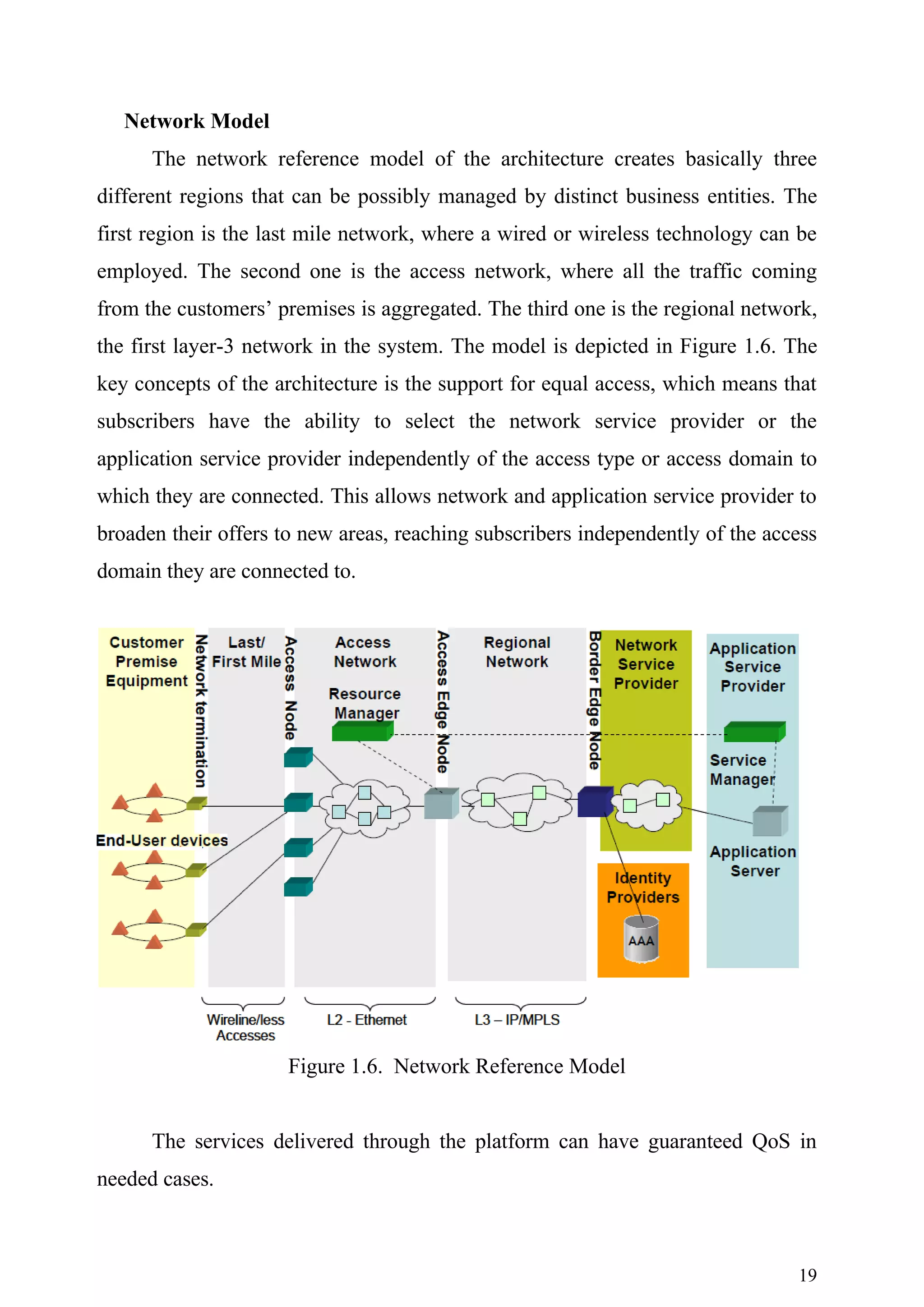
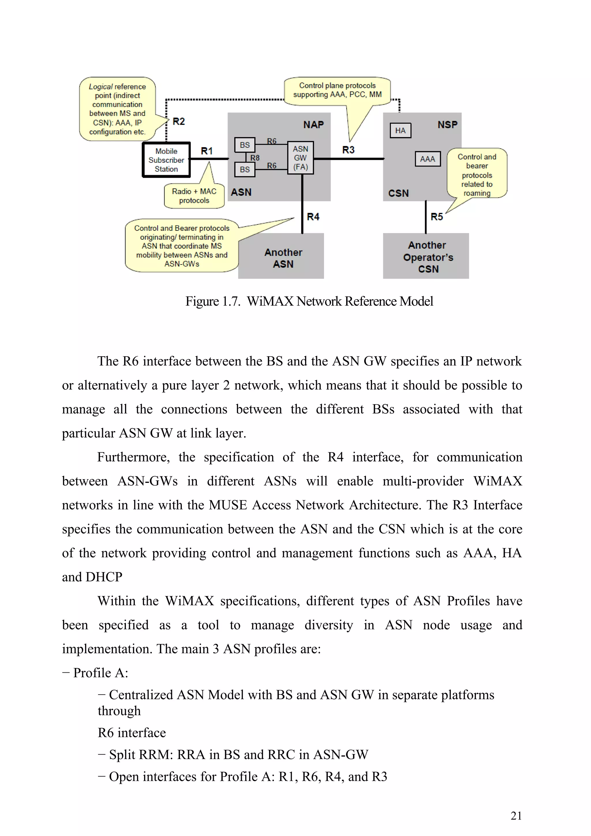
This document is a master's report on quality of service parameters in WiMAX technologies. It contains an introduction that outlines the objectives of comparing the capital expenditures of deploying different broadband network access technologies, including ADSL, ADSL2+, cable, FTTH, and WiMAX. It also discusses geographical and service profiles that will be examined. The methodology draws on several previous European research projects focused on techno-economic analysis of telecommunications networks. The model developed will evaluate the costs of network deployment scenarios across different access technologies and regions.