Safety of Life at Sea (Solas) Weighing Scale Guideccscale
Forthcoming changes to the Safety of Life at Sea (SOLAS) treaty will require that all containers have a verified weight certificate before being loaded on to a ship. The shippers guide is designed to give insight into which Avery Weigh-Tronix products would be useful for the weight verification process. Contact http://www.centralcarolinascale.com for more information.
This is a powerpoint that I had made for my computers in education class. My major is integrated science, so I thought a unit overview slideshow would fit.
THE USE OF AIRBORNE EM CONDUCTIVITY TO LOCATE CONTAMINANT FLOW PATHS AT THE S...Brett Johnson
Richard W. Hammack, Garret A. Veloski, James I. Sams III, and Jennifer S. Shogren
U.S. DOE, National Energy Technology Laboratory, Pittsburgh, PA
Abstract
In 1986, the State of California posted a fish consumption advisory for Clearlake, a large,
freshwater lake located 80 miles north of San Francisco, because of mercury contamination. The
abandoned Sulphur Bank Mercury Mine on the eastern shore of Clearlake is the suspected source of
the mercury. Herman Impoundment, the now flooded open pit of the Sulphur Bank Mercury Mine, is
separated from Clearlake by a dam composed of waste rock removed from the open pit. Hydrological
and geochemical studies indicated that water is flowing from the open pit through the waste rock
dam into Clearlake. However, an accurate map of flow pathways through the waste rock dam was
needed for planning groundwater flow intervention. Results from an airborne EM conductivity survey
flown over the mine site and adjacent areas suggest the probable flow paths taken by the highly
conductive Herman Impoundment water through the waste rock dam. The airborne data were then used
to target areas for ground-based EM conductivity surveys with a Geonics EM34-3XL instrument. The
higher-resolution results of the ground-based survey corroborated the findings of the airborne
survey. This information will allow groundwater-flow intervention efforts to be concentrated within
small areas of the waste rock
dam.
Earth and Life Science
Earth Materials and Processes: Deformation of the Crust
The learners shall be able to:
1) explain how the seafloor spreads (S11/12ESId-23);
2) describe the structure and evolution of ocean basins (S11/12ES-Id-24); and
3) explain how the movement of plates leads to the formation of folds and faults (S11/12ES-Id-22).
Specific Learning Outcomes
At the end of the lesson, the learners will be able to:
1. Discuss the history behind the Theory of Continental Drift;
2. Describe the Continental Drift Theory;
3. Enumerate and explain the evidence used to support the idea of drifting continents;
4. Identify major physiographic features of ocean basins
5. Describe the process of seafloor spreading
By Kevin H a rd y an d Ian KoblickFollowing the theme o .docxclairbycraft
By Kevin H a rd y an d Ian Koblick
Following the theme o f manned undersea habitats, outposts to explore, work and live in the sea, we continue the series with an
excerpt fro m Dr. Joseph M aclnnis’s informative March 1966 Scientific Am erican article “Living under the Sea”.
Ed Link’s Submerged Portable
Inflatable Dwelling (SPID)
By Dr. Joseph B. M a c ln n is
Adapted from
SCIENTIFIC AMERICAN,
March 1966
I
n 1956 Edwin A. Link, the inventor of the Link
Trainer for simulated flight training, was engaged in
undersea archaeological investigations. He recognized
that a diver could work more effectively at substantial
depths if he could live there for prolonged periods instead
of having to be decompressed to the surface after each
day’s work. Link set out to build a vehicle that could
operate as an underwater elevator, a diving bell and a
decompression chamber. The “submersible decompression
chamber” (SDC) he designed is an aluminum cylinder
11 feet long and 3 feet in diameter [see Figure 2], With
its outer hatches closed it is a sealed capsule in which a
diver can be lowered to the bottom. On the bottom, with
the internal gas pressure equal to ambient water pressure
and the hatches open, the SDC serves as a dry refuge from
which the occupant can operate as a free diver. Then, with
the hatches again closed, it becomes a sealed chamber in
which the diver can be decompressed safely and efficiently
on shipboard or during his ascent to the surface. An inner
hatch provides an air lock through which someone else
can enter the chamber (or pass food and other supplies
into it) during the decompression phase.
Early in September 1962, the SDC underwent its
critical test in the Mediterranean Sea off Villefranche on
the French Riviera. A young Belgian diver, Robert Stenuit,
descended in it to 200 feet and lived there for 24 hours,
swimming out into the water to work and returning to rest
in the warm safety of the pressurized chamber. When the
time came to return to the surface, Stenuit did not have
to face hours of dangling on a lifeline or perching on a
platform, decompressing slowly in the cold water. Instead
he sealed himself into the chamber, was hoisted to the
deck of Link’s research vessel, the Sea Diver, and there was
42 The Journal of Diving History First Quarter 2016, Volume 24, Number 86
Figure 1: An underw ater dwelling called the SPID (fo r "subm erged, portable,
inflatable dw elling") was designed by Edwin A. Link as a base o f operations
fo r long dives to the continental shelf, here undergoing a pressure te s t at
70 feet. In the sum m er of 1964 tw o divers occupied the SPID fo r tw o days
at 432 feet below the surface.
HATCH
(OPEN)
Fig u re 2: Two chambers used in the Man in Sea 43 2 -fo o t, tw o-day dive are diagram m ed. The "subm ersible decompression
chamber," or SDC (le ft), is an alum inum cylinder II-fe e t long and 3-feet in Diameter. With the hatches open and the inside gas
.
What is Bermuda Triangle, its exact location, when it was discovered, different theories related to Bermuda Triangle and different incidences related to it.
Bermuda Triangle and Its associated SecretsRohit Satyam
Bermuda Triangle has seen a lot of disappearances of Ships, air crafts, and who knows much more. The presentation focuses on exploring the science and possible reasons behind such disappearances.
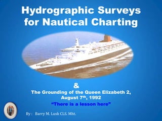
1. Hydrographic Surveys for Nautical Charting & The Grounding of the Queen Elizabeth 2, August 7th, 1992 “There is a lesson here” By : Barry M. Lusk CLS. Mht.
2. Queen Elizabeth 2 was launched in 1967 She was built by John Brown & Company Clydebank, Scotland
4. QE 2 In North America in 1992Why? It was the final evening of a five day pleasure cruise for the 1,824 passengers aboard the British passenger liner Queen Elizabeth 2. Earlier that day she had traveled from Halifax, Canada into Vineyard Sound.
5. The QE 2 anchored in Vineyard Sound for the passengers excursion ashore on August 7, 1992 QE 2 anchored here on August 7th, 1992
6. The passengers were taken into Vineyard Haven and were to be back at the ship and underway at 18:00 Shore excursion here.
7. The QE 2 left the anchorage after 18:00 on August 7, 1992 and followed this route on her way out of the sound North America She was the largest ship ever to enter this Sound
8. This is the QE 2’s out bound track after leaving the anchorage(at 21:44 the speed was set at 20 knots) The pilot set a course of 255 degrees when the navigating officer said 240. The pilot had a plan. Have a look at the near grounding on a 36 foot patch at the buoy. At 20 knots she was drawing almost 36 feet. Therefore her squat wasless than 5 feet.
9. This is the ship board echo trace which shows the depth of the bottom under the keel from the buoy to the grounding site.
10. This is a copy of the 1939 smooth sheet in the area of the grounding. 1.This survey sheet was at a scale of about 1:73,000 ; a mile to the inch. 2. The main sounding lines were 3000 feet apart. 3. The sounding lines over the shoal area shown in yellow were 1500 feet apart. 4. There are 6 lines of soundings over the shoal area. 5. The shoal area is 1.5 nautical miles wide and 0.5 nautical miles at its north/south point. 6. The shoal area, considering the depth of the surrounding area, must be considered a major and significant shoal indication. 7. The area should have been interlined and examined to determine the least depth at the time of the original survey or sometime after. 8. Failure to carry out further surveys to determine the least depth contributed substantially to the grounding of the Queen Elizabeth 2
11. Surveys by NOAA in September 1992 after the grounding. First impact area. Ship grazed over top of a 34.5 foot depth. Ship drawing 32.4 feet and there was 1.5 feet of tide. Therefore squat was about 3.5 feet not 8 feet as NOAA claims. QE 2 on her course of 240 degrees. 3. British Admiralty estimated position. 4. Major impact area 33 feet 5. Ships position at 21:58. Most likely position. 6. End of impact area The Yellowarea shown on the original field sheet. This is the shoal area that should have been examined and is shown again below. . Original smooth sheet 1939.
12. As part of the grounding investigation side scan surveys were conducted This side scan record shows one of the solitary boulders that the QE 2 impacted. The boulder was described by divers as rising approximately 6 feet off the bottom and had a 8 to 10 foot base. Based on the fact that the original 39 foot sound ultimately became a 30 foot sounding it would appear that some of the boulders that were not found as a result of the original sounding lines were 9 feet in height.
13. This is not the QE2 but it shows what damage a grounding can cause Hull damage to the Queen Elizabeth 2 was approximately $20,000,000
14. The Queen Elizabeth 2 back at sea after the repairs Nice, assuming you don’t get “mal de mar”
15. What have we learned from this example of the “Grounding of the QE 2” We have learned the following;
16. What are the surveyors responsibilities Carry out hydrographic sounding surveys based on the expected depth of the water in the survey area. Increase or decrease sounding line separation to reflect anticipated dangers and depth of water. When appreciable shoaling is detected on any main sounding line further examination of the shoal must be undertaken. Examination must continue until the surveyor is certain that the minimum depth has been attained. Not only is a shoal depth required but a bottom sample on the shoal is require in order to determine the nature and composition of the shoal. Failure to determine the least depth on an indicated shoal is in contradiction of all maritime countries hydrographic standing orders. Failure to examine all shoal indications is a dereliction of duty. The surveyor may be held responsible for future groundings on shoals that have not been examined or where the least depth has not been determined.
17. Applicable standards and requirements are from the USGS and NOAA manuals. They are common to all maritime countries hydrographic survey offices The applicable standards and requirements are contained in the 1931 Hydrographic Manual and in the project instructions for this 1939 survey and are mandatory. Some of the standards follow: The standards and requirements which the government failed to observe include the failure to observe and develop the 39 foot sounding discovered on September 7, 1939 and the failure to do additional field work in the area of the 39 foot sounding to determine least depth. The least depth in the area of the 39 foot sounding was required to be found. Quote; “Particular care shall be exercised to obtain and record on their proper times all critical soundings, such as the least depth on ridges and the maximum depth in valleys as those features are crossed.” Further; “A very careful and complete examination to develop the bottom thoroughly and to determine the least depth shall be made regardless of any prearranged system of lines.” The failure to discover the least depth in the area of the 39 foot sounding was a failure to observe HM page 13, paragraph 108 which advises: “ It must not be assumed that the regular system of sounding lines will show the least depth in any region. A sounding showing even slight change from the average depth should be regarded as an indication of a possible shoal and such evidence is greatly increased when shoaler soundings occur on adjacent lines in the same locality.” Further: “ When it may be uneconomical to revisit the locality, the examination shall be made at once. Dropping a marker buoy and temporarily discontinuing the regular line if necessary. Otherwise, the examination should be made as soon as practicable.”