This study focuses on optimizing temperature control in a fast pyrolysis process using a PID controller to enhance bio-oil production. Various tuning methods, including Ziegler-Nichols and Cohen-Coon, were compared, achieving favorable performance with rise times under 3,600 seconds and steady-state errors below 1%. The findings demonstrate that the PID control system is robust and effective in maximizing pyrolytic oil production rates at 500 °C.
![International Journal of Electrical and Computer Engineering (IJECE)
Vol. 14, No. 2, April 2024, pp. 1473~1485
ISSN: 2088-8708, DOI: 10.11591/ijece.v14i2.pp1473-1485 1473
Journal homepage: http://ijece.iaescore.com
Pyrolysis process control: temperature control design and
application for optimum process operation
Bambang Muharto1
, Frendy Rian Saputro1
, Wargiantoro Prabowo1
, Trisno Anggoro1
,
Arya Bhaskara Adiprabowo1,2
, Imron Masfuri1
, Bagus Bhakti Irawan3
1
Bioenergy and Alternative Energy Research Group, Conversion and Conservation Energy Research Center, National Research and
Innovation Agency Indonesia (BRIN), Tangerang, Indonesia
2
Department of Automatic Control and Systems Engineering, The University of Sheffield, Sheffield, United Kingdom
3
Secured Electronic Design Research Group, Research Center for Electronics, National Research and Innovation Agency Indonesia
(BRIN), Tangerang, Indonesia
Article Info ABSTRACT
Article history:
Received Aug 16, 2023
Revised Oct 18, 2023
Accepted Nov 12, 2023
Fast pyrolysis in auger reactor gains attention for efficient bio-oil
production. Due to the quick nature of the process, precise temperature
control using the proportional-integral-derivative (PID) algorithm is
paramount. This study harnesses various PID tuning approaches through
modelling and experimental validation to optimize continuous and precise
pyrolysis temperature. System identification was done to investigate the
process dynamic with fit accuracy above 93% and design a suitable PID
control. Comparison with the experiment data shows a favorable result with
rise time and settling time match above 75%. Ziegler-Nichols (ZN) and
Cohen-Coon (CC) tuning methods were implemented in the system with
undistinguished results, yielding steady-state error (SSE) below 1% and
settling time around 4,300 to 4,800 seconds. The heuristic fine-tuning
method improved the rise time and settling time by stabilizing before
3,600 seconds. Furthermore, the robustness of PID controllers was verified
with a disturbance rejection test, keeping the SSE deviation inside the
boundary of 2%. Finally, the setup could support maximum pyrolytic oil
production by 69.6% at 500 °C. The result implies that the PID controller
could provide a stable and rugged response to support a productive and
sustainable pyrolysis plant operation.
Keywords:
Auger reactor
Control system design
Proportional-integral-derivative
control
Pyrolysis
Temperature regulation
This is an open access article under the CC BY-SA license.
Corresponding Author:
Bambang Muharto
Bioenergy and Alternative Energy Research Group, Conversion and Conservation Energy Research Center,
National Research and Innovation Agency Indonesia (BRIN)
KST BJ Habibie Energy Building, Tangerang Selatan, Indonesia
Email: bamb052@brin.go.id
1. INTRODUCTION
In 2010, the global energy consumption was apportioned among different sources, with oil
representing 35.3%, coal at 27.0%, natural gas at 20.5%, biomass at 6.3%, nuclear at 5%, hydroelectric at
5.8%, and other renewables at 1.1% [1]. Based on predictions, there will be a considerable increase in the
global development and application of sustainable energy solutions, primarily driven by their environmental
benefits and the uncertainties associated with an approximate 56% rise in total energy demand [2]. Moreover,
forecasts suggest a 20% reduction in oil consumption and a twofold increase in the usage of renewable
energy by 2040 [3].](https://image.slidesharecdn.com/v2634009ijecedby-240404063816-a200ac9f/85/Pyrolysis-process-control-temperature-control-design-and-application-for-optimum-process-operation-1-320.jpg)
![ ISSN: 2088-8708
Int J Elec & Comp Eng, Vol. 14, No. 2, April 2024: 1473-1485
1474
The utilization of renewable sources and repurposing waste materials for energy is on the rise due to
many factors, including society's heavy reliance on fossil fuels and growing apprehensions about the impacts
of global warming [4]. Climate change and rising energy needs caused by rapid worldwide population
increase, urbanization, industrialization, and national development advancements have resulted in massive
waste generation, posing a threat to the environment and human health. Furthermore, trash disposal at
landfills leads to the release of greenhouse gases. Sustainable waste management strategies contribute to
reducing waste generation, optimizing waste reuse and recycling, and mitigating waste's environmental
consequences [5]. Moreover, harnessing energy from sustainable sources is a potential solution to minimize
climate change impact and the surging global temperature, as recognized by the intergovernmental panel on
climate change (IPCC) and international climate change conventions [6].
Thermochemical conversion methods and integrating comprehensive waste management systems
are the best solutions for sustainable waste treatment [7]. The utilization of thermochemical conversion
methods to transform fossil-based and bio-based waste into alternative liquid fuels can contribute to a future
[8]. One of the thermochemical conversion methods is pyrolysis, a thermochemical decomposition process of
organic materials conducted without any oxidant, typically at elevated temperatures ranging from 400 °C to
800 °C [9]. The categorization of pyrolysis is divided into slow, fast, or flash depending on the reactor's
heating rate and the system's residence time [10], [11].
The fast pyrolysis process has captured the attention of researchers mainly because it has the
potential to produce a more significant amount of bio-oil compared to the other two techniques [12]. The
primary output of fast pyrolysis in liquid form facilitates its simple storage and transportation. Additionally, a
diverse array of reactors is suitable for performing fast pyrolysis. One of them is the auger-type reactor,
which stands out for its uncomplicated operation and handling. As a result, the auger reactor is considered
one of the most potential reactor configurations for the fast pyrolysis process [13].
Several researchers have explored using the fast pyrolysis process and an auger reactor.
Jalalifar et al. [14] conducted an experiment that utilized a fast pyrolysis process in a pilot-scale auger reactor
modelled through computational fluid dynamic (CFD) simulation. The optimal temperature for maximizing
the bio-oil yield was 500 °C for the specific feedstock and reactor. Moreover, higher feed flow rates within
the studied range of biomass feed flow rates (1–4 kg/h) led to increased bio-oil yield. Huo et al. [15] carried
out experiments to explore the liquid product yields from the catalytic pyrolysis of low-density polyethylene
(LDPE), resulting in yields of 60.9 wt% (450 °C), 72 wt% (500 °C), and 68.5 wt% (600 °C).
Precise temperature measurement and control are pivotal in numerous industrial and scientific
processes. However, achieving rapid and accurate temperature changes with high stability becomes
challenging when intricate thermal interactions arise among the heat source, controlled mass, and heat sink
within traditional heater-controlled systems [16]. The controller's accuracy and sensitivity influence the
precision of temperature regulation in a heater [17], [18]. Hasan et al. [13] stated in their research that
different temperatures can lead to a 10%–20% difference in the bio-oil yield. Elevating the pyrolysis
temperature leads to volatile cracking processes, resulting in a decline in bio-oil yield and increased gas
generation. Conversely, lowering the temperature promotes the production of significant amounts of biochar.
According to Greco et al. [19] a dependable temperature controller is crucial to ensure temperature
stability when the pyrolysis reactor is in continuous operation. Despite the emergence of new controller
algorithm candidates, such as model predictive control (MPC), proportional-integral-derivative (PID)-fuzzy,
and neural network-based methods like reinforcement learning (RL), proportional-integral-derivative (PID)
controller supremacy remains undisputed due to its reliability, versatility over various process application and
operating condition, easily obtained hardware, well-known by engineers and operators, coupled with its
ability to maintain stability despite disturbance and fast response [20]–[22]. Furthermore, a survey conducted
by Samad et al. [23] revealed that PID control still had a current impact of 91% and will maintain the impact
in the next five years by 78%. To date, PID controllers have seen countless successful implementations with
various tuning methods, such as modified grey wolf optimization (mGWO) for liquid level control [24],
improved Marine predators algorithm tuned with additional fractional-order tuning parameter for automatic
voltage regulator (AVR) system [25], and back propagation neural network (BPNN) for a motion control
system embedded in a field programmable gate array (FPGA) [26]. Its adaptability extends to linear and
nonlinear systems, irrespective of their response speed [20]. The standard approaches for tuning PID
controllers are Ziegler-Nichols (ZN), relay method, Cohen-Coon (CC), and Chien-Hrones-Reswick methods
[27]–[30].
The goal of this research is to design and implement a robust and stable PID control system that
supports pyrolysis plant operation through a combination of simulation and experimental methods.
Simulation is done by creating the plant mathematical model to design the PID controller by system
identification method taken from the pseudo-random binary sequence (PRBS) technique. The outcome was
then contrasted with the actual experiment data to determine the match percentage. Three tuning methods](https://image.slidesharecdn.com/v2634009ijecedby-240404063816-a200ac9f/85/Pyrolysis-process-control-temperature-control-design-and-application-for-optimum-process-operation-2-320.jpg)
![ ISSN: 2088-8708
Int J Elec & Comp Eng, Vol. 14, No. 2, April 2024: 1473-1485
1476
Figure 2. Proportional-integral-derivative (PID) controller block diagram
These S-shaped curves are described by two constants known as the delay time (L) and time
constant (T). A tangent line is drawn by the inflexion point of the S-shaped curve to determine these values.
The variables, such as the percent change of input (P), the percent change of output (N), dead time (L) and
time (R), will be used as input for ZN [31] and CC tuning rules [32] as described in Figure 3 and Table 1.
Figure 3. S-curve for ZN and CC tuning methods
Table 1. Ziegler-Nichols (ZN) and Cohen-Coon (CC) PID tuning rule
PID tuning method 𝐾𝑝 𝑇𝑖 𝑇𝑑
ZN
1.2
T
L
2L 0.5L
CC
(
P
NL
)(1.33 + (
R
4
)) L (
30 + 3R
9 + 20R
)
4L
(11 + 2R)
The system requirements for the pyrolysis temperature control can be seen in Table 2. The setpoint
is set at 500 °C, with a maximum allowable overshoot of 2% to minimize temperature deviation and avoid a
decline in the bio-oil product [13]. As indicated by the rise time requirement of ≤3,000 seconds, a fast
response is required to minimize the time to reach the setpoint. The steady-state error must be kept under 2%
by the control system's basic rule [31]. Moreover, the settling time should also be ≤3,600 seconds to maintain
temperature stability within an acceptable range around the setpoint.
Table 2. Control system design requirement
Requirement Value
Setpoint 500 °C
Maximum overshoot 2%
Rise time ≤3,000 s
Steady-state error ≤2%
Settling time ≤3,600 s](https://image.slidesharecdn.com/v2634009ijecedby-240404063816-a200ac9f/85/Pyrolysis-process-control-temperature-control-design-and-application-for-optimum-process-operation-4-320.jpg)

![ ISSN: 2088-8708
Int J Elec & Comp Eng, Vol. 14, No. 2, April 2024: 1473-1485
1478
gain profound insights into its dynamic behavior and inherent properties. Furthermore, it facilitates the
creation of precise mathematical models based on real-time measurements and experimental data, a crucial
step in designing effective control strategies for optimizing and regulating the system's behavior [33].
3.1.1. Transfer function plant identification for PID simulation
There are three main steps in getting the transfer function of the system model. First, data
acquisition consists of open-loop input and output data [34]. A total of 7,150 data points were taken for each
control loop, with the input from the SSR ranging from 0 to 100% that triggered the heating command in the
reactor and the output is the measured reactor temperature. A PRBS signal was chosen to generate the output
response due to its simplicity for iterative signal generation and producing the desired result, triggering the
output continuously [35]. Figure 6 depicts the input and output of the open loop system using the system
identification toolbox in MATLAB.
After data acquisition, the second step is model estimation using the system identification toolbox in
MATLAB. The estimation process is done to obtain the highest fit percentage. Continuous transfer functions
for each loop were identified utilizing the transfer function identification (TFEST) command with no zeros,
two poles and three free coefficients. Table 3 displays the result with over 90% fit estimation data for T3, T4,
and T5.
Figure 6. Input and output signal
Table 3. Identification of transfer function
Transfer function Fit estimation data
T3 1.861𝑒 − 05
𝑠2 + 0.005205𝑠 + 8.138𝑒 − 07
93.88%
T4 1.737𝑒 − 05
𝑠2 + 0.004285𝑠 + 6.179𝑒 − 07
94.40%
T5 1.052𝑒 − 05
𝑠2 + 0.002795𝑠 + 5.75𝑒 − 07
93.71%
3.1.2. PID simulation transient response
There are four main classifications of damping ratio (ζ) in control engineering design. First,
undamped (𝜁 = 0) with no damping in the system and sustained oscillation. Second, underdamped
(0 < 𝜁 < 1), with fast rise time and overshoot in the response. Third, critically damped (𝜁 = 1) with slower
rise time compared to underdamped and minimum overshoot. Finally, overdamped (𝜁 > 1), with the slowest
rise time among all. Figure 7 shows the response comparison between different values of the damping ratio.
For the pyrolysis temperature control design, the simulation will start with a critically damped
system with 𝜁 = 1. After achieving a critically damped ratio, the PID parameters will be subsequently tuned
to meet the design requirements, as indicated in Table 2. Figure 8 shows the transient response from the
simulation result, and Table 4 displays the detailed specification parameter.
The system simulation response for the rise time, settling time, and steady-state error showed that
the selected values for 𝐾𝑝, 𝑇𝑖, and 𝑇𝑑 have met the minimum requirement described in Table 2. The settling
times, achieved when the steady-state error is less than 2%, are 2,300 seconds, 2,650 seconds, and
2,760 seconds, respectively, for T3 to T5. However, the maximum overshoot for T3, T4, and T5 exceeds the
minimum requirement, with values of 6.42%, 9.84%, and 9.42%, respectively. Hence, ZN and CC tuning
methods will be used to reduce the overshoot.
0 1000 2000 3000 4000 5000 6000 7000 8000
0
50
100
150
200
250
300
350
400
Time (s)
Output
(
o
C)
T3 T4 T5
0 1000 2000 3000 4000 5000 6000 7000 8000
-20
0
20
40
60
80
100
120
Input
(%)
Time (s)
Input](https://image.slidesharecdn.com/v2634009ijecedby-240404063816-a200ac9f/85/Pyrolysis-process-control-temperature-control-design-and-application-for-optimum-process-operation-6-320.jpg)
![Int J Elec & Comp Eng ISSN: 2088-8708
Pyrolysis process control: temperature control design and application for … (Bambang Muharto)
1479
Figure 7. Response comparison of damping ratio [31]
Figure 8. PID simulation result
Table 4. Specification parameter of the PID simulation
𝐾𝑝 𝑇𝑖 (s) 𝑇𝑑 (s) Max overshoot (%) Rise time (s) Settling time (s) Steady state error (%)
T3 0.70 100 10 6.42 588 2300 < 2
T4 0.65 100 20 9.84 577 2650 < 2
T5 0.55 110 50 9.42 787 2760 < 2
3.2. Comparison between simulation and experiment response
The simulation-based tuning method yielded transient response values that substantially diverged
from the experimental results. Notably, the overshoot values were considerably high for scenarios T4 and T5,
reaching 15.98% and 16.21%, respectively. This significant discrepancy indicates that the simulation might
not fully capture the intricacies of the actual pyrolysis process, underlining the challenge of accurately
modelling its dynamic behavior [36]. The rise times were relatively rapid, ranging from 438 to 545 seconds,
showing the potential for quick control responses. However, the elevated overshoots underscore the
limitations of relying solely on simulation for parameter tuning.
The transient response results obtained from simulation and implementation for T3, T4, and T5 of
the pyrolysis temperature control exhibit varying degrees of similarity and deviation. Table 5 shows the
percentage of match simulation and implementation data. T3 demonstrates a relatively good match in rise
time and settling time between simulation and implementation (86.23% and 92.46%, respectively), while the
overshoot notably deviates (10.46% compared to 6.42% in simulation). In T4, the rise time and settling time
exhibit better correspondence (75.93% and 75.09%, respectively), yet the overshoot differs significantly
(15.98% compared to 9.84% in simulation). T5 shows a reasonable fit in rise time (30.78%) but deviates
notably in overshoot and settling time (16.21% and 3,226 seconds compared to 9.42% and 2,760 seconds in
simulation). Overshoot of overall sections shows the lowest match compared to another transient parameter,](https://image.slidesharecdn.com/v2634009ijecedby-240404063816-a200ac9f/85/Pyrolysis-process-control-temperature-control-design-and-application-for-optimum-process-operation-7-320.jpg)
![ ISSN: 2088-8708
Int J Elec & Comp Eng, Vol. 14, No. 2, April 2024: 1473-1485
1480
with less than 40%. The actual overshoot of the system is barely reduced due to the system having no
cooling. The system with no cooling and only depends on the natural effect is slow in reducing temperature
[37].
Table 5. Percentage of match simulation and implementation data
Max overshoot match (%) Rise time match (%) Settling time match (%)
T3 37.02 86.23 92.46
T4 37.90 75.93 75.09
T5 28.35 69.22 85.46
The experimental tuning phase involved conducting an open-loop experiment to obtain the S curve
of the system. By observing the system's response without any feedback control, the inherent dynamics and
characteristics of the system were identified. Subsequently, the ZN and CC tuning rules were implemented
based on the obtained S curve as described in [31], [32], [36] . These tuning methods allowed for determining
appropriate PID controller parameters, including the proportional, integral, and derivative gains, to achieve
the desired control performance. The experimental tuning process enabled a systematic approach to optimize
the control strategy for the specific pyrolysis process, ensuring accurate and stable temperature control.
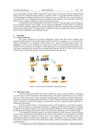
Figure 9 shows the PID controller's response to various tuning methods, with the result of simulation
validation in Figure 9(a) seen with overshoot, the real-time implementation of ZN, CC method in
Figures 9(b) and 9(c), and the improvement done by empirical fine-tuning method in Figure 9(d). ZN and CC
tuning methods exhibit competitive transient responses in overshoot, rise time, settling time, and steady-state
error. Both methods managed to maintain values below 0.317% for overshoot, indicating their effectiveness
in controlling temperature deviations. On the other hand, the rise time obtained with CC tuning is notably
shorter than the ZN tuning's range of 400 seconds. A shorter rise time is highly beneficial in dynamic systems
like pyrolysis, where precise temperature control is crucial for optimal product yield and energy efficiency
[19]. It enhances the process's responsiveness to external factors, such as variations in feedstock composition
or heating conditions, which can directly impact the product quality and process efficiency. Therefore, the
superiority of CC tuning in achieving shorter rise times underscores its potential to provide more agile and
accurate control in the pyrolysis temperature control process.
PID parameter and transient response can be seen in Table 6. Comparing the settling time achieved
through the ZN and CC tuning methods, it is evident that both methods yield relatively similar results. The
settling time for CC ranges from 4,380 to 4,880 seconds, while those for ZN range from 4,443 to
4,750 seconds. These values indicate that both methods provide adequate control performance regarding how
quickly the system maintained a steady-state condition. Notably, both methods achieved steady-state errors
well below 1%, highlighting their competence in process regulation vigilance.
Among these methods, the CC tuning method is the most suitable for precise pyrolysis temperature
control due to its effective balance between performance and stability. However, its settling time might fall
short of the minimum requirement. Therefore, a heuristic adjustment based on the CC tuning method is
needed to achieve the desired results, which is called fine-tuning [36], [38]. This will act as a crucial
refinement step that bridges theoretical predictions with practical implementation, enabling optimization
tailored to the pyrolysis process dynamics.
The fine-tuning method meticulously addresses the intricacies of the specific system dynamics
through iterative parameter adjustment. The interplay between 𝐾𝑝, 𝑇𝑖, and 𝑇𝑑 in a PID control system
profoundly shapes the control response for dynamic processes [36]. The PID parameter spectrum spans from
initial simulation-based values to those derived from ZN and CC methods.
Given that 𝑇𝑑 values from the CC method are well-suited for reducing overshoot and anticipating
future errors, the primary modification focus is on Kp and 𝑇𝑖. The challenge in pyrolysis temperature control
lies in balancing 𝐾𝑝 and 𝑇𝑖 to achieve rapid temperature adjustments without overshooting. A high 𝐾𝑝
coupled with a small 𝑇𝑖 accelerates response but can destabilize, while a small 𝐾𝑝 with a large 𝑇𝑖 stabilizes at
the cost of slower convergence. Therefore, the objective is to find the equilibrium between 𝐾𝑝 and 𝑇𝑖 that
ensures a swift response, stability, and minimal deviation in temperature control, which is crucial for efficient
pyrolysis.
The procedure of fine-tuning method is as follows. First, the PID parameters of the CC method were
initialized to the system, and the 𝑇𝑑 parameter was kept constant. Second, the 𝐾𝑝 parameter was decreased by
around half to a quarter of the initial value, and the 𝑇𝑖 parameter was adjusted. Finally, the pyrolysis plant
was restarted again to check the settling time requirement. If the requirement is not fulfilled, then the 𝐾𝑝 and
𝑇𝑖 parameters are readjusted again.](https://image.slidesharecdn.com/v2634009ijecedby-240404063816-a200ac9f/85/Pyrolysis-process-control-temperature-control-design-and-application-for-optimum-process-operation-8-320.jpg)
![ ISSN: 2088-8708
Int J Elec & Comp Eng, Vol. 14, No. 2, April 2024: 1473-1485
1482
Figure 10. Disturbance rejection test result
The positioning of T3 causes a discrepancy in oscillation ranges as it is the first contact point with
the waste. This initial point of contact exposed T3 to the fresh tyre waste material, leading to higher
disturbances and relatively frequent oscillation due to the heat transfer. Moreover, the speed at which T3
reaches its setpoint of stability, approximately 500 seconds, emphasizes its sensitivity to disturbances.
This observation resonates with the fine-tuning results, where the fine-tuning approach significantly
reduced overshoots and steady-state errors. The fine-tuning parameters align the system's response more
closely with the desired setpoints, thus dampening the oscillations caused by external disturbances. The other
two sections (T4 and T5) also play crucial roles. The dampened oscillation in T3, T4, and T5 showcases the
effectiveness of fine-tuning in achieving stable control across all sections of the pyrolysis reactor.
3.4. Production result
The pyrolysis plant was operated with fine-tuning PID set-up, tyre waste feed of 13.33 g/min, and
various setpoints ranging from 400 °C to 600 °C. The result is then recorded in Table 7. It was observed that
the highest oil yield was reached at the 500 °C setpoint, with 69.6 wt%, corresponding with the studies in [8],
[15], and [39]. Therefore, the fine-tuning PID setup was able to support maximum pyrolytic oil production by
maintaining the plant’s temperature at 500 °C.
Table 7. Pyrolysis plant product yield
Setpoint (°C) Oil (liquid) yield (wt%) Solid (char) yield (wt%) Non-condensable gas (wt%)
400 52.2 43.99 3.81
500 69.6 23.82 6.58
600 63 25.77 11.23
4. CONCLUSION
Robust and stable PID controllers were designed and implemented successfully for every control
loop in the pyrolysis reactor. The system identification method was employed to determine the transfer
function from the data excited by the PRBS signal, with the fit estimation data of 93.88%, 94.40% and
93.71% for T3, T4 and T5, respectively. PID controllers for simulation purposes were created with minimum
overshoot, error steady state below 2%, and settling time of less than 3,000 seconds for each control loop,
fulfilling the system’s requirement. Although the PID controllers' simulation result and field implementation
had a considerable difference below 40% for the overshoot condition, it shows an agreeable similarity in rise
and settling time ranging from 69.22% to 92.46% for T3 to T5.
The applied PID controllers were tuned under ZN and CC. Both have an identical response with
steady-state error and a maximum overshoot of less than 1%. However, the settling time is outside the
requirement. Therefore, an intuitively improved CC method (fine-tuning) is deployed to fasten the settling
time to 3,008, 2,605, and 3,208 seconds for T3, T4 and T5 at the expense of negligible overshoot. The
disturbance rejection test showed that PID controllers could maintain the reactor temperatures inside error
steady-state criteria of 2% for T3 and 1% for T4 and T5 despite feed input. Moreover, the tuning
implementation into the pyrolysis plant could support pyrolytic production impeccably by 69.6 wt% at
500 °C.
This investigation offers another insight into the proposed self-tuning CC method that fastens the
response’s settling time and reinforces pyrolytic oil optimal production. On the other hand, the similarity
0 250 500 750 1000 1250 1500
400
425
450
475
500
525
550
Temperature
(
o
C)
Time (s)
T3 T4 T5 Set Value](https://image.slidesharecdn.com/v2634009ijecedby-240404063816-a200ac9f/85/Pyrolysis-process-control-temperature-control-design-and-application-for-optimum-process-operation-10-320.jpg)
![Int J Elec & Comp Eng ISSN: 2088-8708
Pyrolysis process control: temperature control design and application for … (Bambang Muharto)
1483
between the transfer function estimation and the experiment result is justified by the rise and settling time
match. The present study lays the groundwork for future research in performing other methods such as MPC,
RL, and PID-fuzzy to develop the controller to minimize control input or simplify the tuning process.
ACKNOWLEDGEMENTS
This research was funded by the Program House of Renewable Energy National Research and
Innovation Agency (BRIN) for the fiscal year 2022. It is included in the research activities of the Bioenergy
and Alternative Energy Research Group.
REFERENCES
[1] T. M. Letcher, “Introduction with a focus on atmospheric carbon dioxide and climate change,” in Future Energy, Elsevier, 2020,
pp. 3–17.
[2] S. K. Sansaniwal, K. Pal, M. A. Rosen, and S. K. Tyagi, “Recent advances in the development of biomass gasification
technology: a comprehensive review,” Renewable and Sustainable Energy Reviews, vol. 72, pp. 363–384, May 2017, doi:
10.1016/j.rser.2017.01.038.
[3] M. Shahbaz et al., “A comprehensive review of biomass based thermochemical conversion technologies integrated with CO2
capture and utilisation within BECCS networks,” Resources, Conservation and Recycling, vol. 173, Oct. 2021, doi:
10.1016/j.resconrec.2021.105734.
[4] J. D. Martínez, N. Puy, R. Murillo, T. García, M. V. Navarro, and A. M. Mastral, “Waste tyre pyrolysis – a review,” Renewable
and Sustainable Energy Reviews, vol. 23, pp. 179–213, Jul. 2013, doi: 10.1016/j.rser.2013.02.038.
[5] D. C. Wilson, C. A. Velis, and L. Rodic, “Integrated sustainable waste management in developing countries,” Proceedings of the
Institution of Civil Engineers - Waste and Resource Management, vol. 166, no. 2, pp. 52–68, May 2013, doi:
10.1680/warm.12.00005.
[6] R. G. Newell, D. Raimi, and G. Aldana, “Global energy outlook 2019: The next generation of energy,” Resources for the future,
2019.
[7] H. Durak, “Comprehensive assessment of thermochemical processes for sustainable waste management and resource recovery,”
Processes, vol. 11, no. 7, Jul. 2023, doi: 10.3390/pr11072092.
[8] F. Abnisa and W. M. A. Wan Daud, “A review on co-pyrolysis of biomass: an optional technique to obtain a high-grade pyrolysis
oil,” Energy Conversion and Management, vol. 87, pp. 71–85, Nov. 2014, doi: 10.1016/j.enconman.2014.07.007.
[9] M. Wang, L. Zhang, A. Li, M. Irfan, Y. Du, and W. Di, “Comparative pyrolysis behaviors of tire tread and side wall from waste
tire and characterization of the resulting chars,” Journal of Environmental Management, vol. 232, pp. 364–371, Feb. 2019, doi:
10.1016/j.jenvman.2018.10.091.
[10] R. N. Mandapati and P. K. Ghodke, “Kinetic modeling of Indian lignites pyrolysis in the context of underground coal gasification
(UCG),” Fuel, vol. 283, Jan. 2021, doi: 10.1016/j.fuel.2020.118939.
[11] Z. Ullah et al., “An integrated framework of data-driven, metaheuristic, and mechanistic modeling approach for biomass
pyrolysis,” Process Safety and Environmental Protection, vol. 162, pp. 337–345, Jun. 2022, doi: 10.1016/j.psep.2022.04.013.
[12] P. Brassard, S. Godbout, and V. Raghavan, “Pyrolysis in auger reactors for biochar and bio-oil production: a review,” Biosystems
Engineering, vol. 161, pp. 80–92, Sep. 2017, doi: 10.1016/j.biosystemseng.2017.06.020.
[13] M. M. Hasan, M. G. Rasul, M. M. K. Khan, N. Ashwath, and M. I. Jahirul, “Energy recovery from municipal solid waste using
pyrolysis technology: A review on current status and developments,” Renewable and Sustainable Energy Reviews, vol. 145, Jul.
2021, doi: 10.1016/j.rser.2021.111073.
[14] S. Jalalifar et al., “CFD analysis of fast pyrolysis process in a pilot-scale auger reactor,” Fuel, vol. 273, Aug. 2020, doi:
10.1016/j.fuel.2020.117782.
[15] E. Huo et al., “Jet fuel and hydrogen produced from waste plastics catalytic pyrolysis with activated carbon and MgO,” Science of
The Total Environment, vol. 727, Jul. 2020, doi: 10.1016/j.scitotenv.2020.138411.
[16] C. Park and W. Joung, “Effect of heat load on pneumatic temperature control characteristics of a pressure-controlled loop heat
pipe,” International Journal of Heat and Mass Transfer, vol. 186, May 2022, doi: 10.1016/j.ijheatmasstransfer.2021.122472.
[17] G. Ulpiani, M. Borgognoni, A. Romagnoli, and C. Di Perna, “Comparing the performance of on/off, PID and fuzzy controllers
applied to the heating system of an energy-efficient building,” Energy and Buildings, vol. 116, pp. 1–17, Mar. 2016, doi:
10.1016/j.enbuild.2015.12.027.
[18] J. Yuan et al., “Identification heat user behavior for improving the accuracy of heating load prediction model based on wireless
on-off control system,” Energy, vol. 199, May 2020, doi: 10.1016/j.energy.2020.117454.
[19] G. Greco, C. Di Stasi, F. Rego, B. González, and J. J. Manyà, “Effects of slow-pyrolysis conditions on the products yields and
properties and on exergy efficiency: A comprehensive assessment for wheat straw,” Applied Energy, vol. 279, Dec. 2020, doi:
10.1016/j.apenergy.2020.115842.
[20] M. B. N. Shah et al., “PID-based temperature control device for electric kettle,” International Journal of Electrical and Computer
Engineering (IJECE), vol. 9, no. 3, pp. 1683–1693, Jun. 2019, doi: 10.11591/ijece.v9i3.pp1683-1693.
[21] Q. Bu et al., “The effect of fuzzy PID temperature control on thermal behavior analysis and kinetics study of biomass microwave
pyrolysis,” Journal of Analytical and Applied Pyrolysis, vol. 158, Sep. 2021, doi: 10.1016/j.jaap.2021.105176.
[22] N. Divya, S. Manoharan, J. Arulvadivu, and P. Palpandian, “An efficient tuning of fractional order PID controller for an industrial
control process,” Materials Today: Proceedings, vol. 57, pp. 1654–1659, 2022, doi: 10.1016/j.matpr.2021.12.255.
[23] T. Samad et al., “Industry engagement with control research: Perspective and messages,” Annual Reviews in Control, vol. 49,
pp. 1–14, 2020, doi: 10.1016/j.arcontrol.2020.03.002.
[24] J. Bhookya, M. V. Kumar, J. R. Kumar, and A. S. Rao, “Implementation of PID controller for liquid level system using mGWO
and integration of IoT application,” Journal of Industrial Information Integration, vol. 28, 2022, doi: 10.1016/j.jii.2022.100368.
[25] M. Z. Mohd Tumari, M. A. Ahmad, M. H. Suid, and M. R. Hao, “An improved Marine predators algorithm-tuned fractional-order
PID controller for automatic voltage regulator system,” Fractal and Fractional, vol. 7, no. 7, Jul. 2023, doi:
10.3390/fractalfract7070561.
[26] J. Wang, M. Li, W. Jiang, Y. Huang, and R. Lin, “A design of FPGA-based neural Network PID controller for motion control
system,” Sensors, vol. 22, no. 3, Jan. 2022, doi: 10.3390/s22030889.](https://image.slidesharecdn.com/v2634009ijecedby-240404063816-a200ac9f/85/Pyrolysis-process-control-temperature-control-design-and-application-for-optimum-process-operation-11-320.jpg)
![ ISSN: 2088-8708
Int J Elec & Comp Eng, Vol. 14, No. 2, April 2024: 1473-1485
1484
[27] Š. Bucz, A. Kozáková, and V. Veselý, “Robust PID controller design for performance based on ultimate plant parameters,” IFAC-
PapersOnLine, vol. 48, no. 14, pp. 388–395, 2015, doi: 10.1016/j.ifacol.2015.09.488.
[28] I. D. Díaz-Rodríguez, S. Han, L. H. Keel, and S. P. Bhattacharyya, “Advanced tuning for Ziegler-Nichols plants,” IFAC-
PapersOnLine, vol. 50, no. 1, pp. 1805–1810, Jul. 2017, doi: 10.1016/j.ifacol.2017.08.168.
[29] M. H. Suid and M. A. Ahmad, “Optimal tuning of sigmoid PID controller using nonlinear sine cosine algorithm for the automatic
voltage regulator system,” ISA Transactions, vol. 128, pp. 265–286, Sep. 2022, doi: 10.1016/j.isatra.2021.11.037.
[30] J. Fernández-Ramos, L. Narvarte, R. López-Soria, R. H. Almeida, and I. B. Carrêlo, “An assessment of the proportional-integral
control tuning rules applied to photovoltaic irrigation systems based on standard frequency converters,” Solar Energy, vol. 191,
pp. 468–480, Oct. 2019, doi: 10.1016/j.solener.2019.09.021.
[31] K. Ogata, Modern control engineering, 5th Edition. Prentice Hall, 2010.
[32] P. Woolf, “Chemical process dynamics and controls,” University of Michigan: Ann Arbor, MI, USA, 2009. Accessed: Aug. 14, 2023.
[Online], Available: https://open.umich.edu/sites/default/files/downloads/chemical_process_dynamics_and_controls-book_1.pdf
[33] M. J. Rabbani, K. Hussain, A.-R. Khan, and A. Ali, “Model identification and validation for a heating system using MATLAB
system identification Toolbox,” IOP Conference Series: Materials Science and Engineering, vol. 51, Dec. 2013, doi:
10.1088/1757-899X/51/1/012022.
[34] A. S. Bappah, “Hands-on industrial process modelling using the MATLAB system identification Toolbox,” in Industrial
Engineering, Management Science and Applications, 2015, pp. 85–93.
[35] S. S. Wilson, “Understanding the PRBS signal as an optimum input signal in the wavelet-correlation method of system
identification using multiresolution analysis,” in Proceedings. IEEE SoutheastCon, 2005., pp. 39–44, doi:
10.1109/SECON.2005.1423213.
[36] D. Seborg, T. Edgar, D. Mellichamp, and F. D. III, Process dynamics and control. John Wiley & Sons, 2016.
[37] A. Budianto, W. S. Pambudi, S. Sumari, and A. Yulianto, “PID control design for biofuel furnace using Arduino,” TELKOMNIKA
(Telecommunication Computing Electronics and Control), vol. 16, no. 6, Dec. 2018, doi: 10.12928/telkomnika.v16i6.9770.
[38] A. G. Daful, “Comparative study of PID tuning methods for processes with large & small delay times,” in 2018 Advances in
Science and Engineering Technology International Conferences (ASET), Feb. 2018, pp. 1–7, doi:
10.1109/ICASET.2018.8376915.
[39] W. Han, D. Han, and H. Chen, “Pyrolysis of waste tires: a review,” Polymers, vol. 15, no. 7, Mar. 2023, doi:
10.3390/polym15071604.
BIOGRAPHIES OF AUTHORS
Bambang Muharto received a B.Sc. degree in electronics and instrumentation
from Universitas Gadjah Mada, Indonesia, in 2015. He is pursuing his master's degree in
embedded systems from the University of Twente, Netherlands. From 2018 to 2021, he was an
electronic engineer with The Agency for the Assessment and Application of Technology
(BPPT). Since 2022, he has worked as a researcher at the National Research and Innovation
Agency (BRIN) in Indonesia. His research interests include the development of
comprehensive hardware and software solutions, sensor development, data acquisition and
analysis, control systems and automation, and sustainability in monitoring systems and control
for bioenergy processing. He can be contacted at email: bamb052@brin.go.id.
Frendy Rian Saputro received his bachelor's degree in mechanical engineering
from Universitas Indonesia, Indonesia, in 2013, and the design and development of a cylinder
block and crankcase of four-stroke internal combustion engine with 65 cc capacity as the final
project theme for the bachelor’s degree. He is pursuing his master of philosophy in mechanical
engineering from the Universiti Teknologi Malaysia, Malaysia. From 2015 to 2021, he worked
as a mechanical engineer at the Agency for the Assessment and Application of Technology
(BPPT). Since 2022, he has worked as a researcher at the National Research and Innovation
Agency (BRIN) in Indonesia. His research interests include engineering design,
manufacturing, simulation, fuels, internal combustion engines, and energy conversion. He can
be contacted at email: fren002@brin.go.id.
Wargiantoro Prabowo received a bachelor's degree in mechanical engineering
from Lampung University, Lampung, Indonesia, in 2007, and the air conditioning system
(HVAC) as the final project theme for the bachelor's degree. He is pursuing his master of
philosophy in mechanical engineering from the Universiti Teknologi Malaysia, Malaysia. He
is a researcher at the National Research and Innovation Agency Republic of Indonesia
(BRIN). From 2009-2021, he worked as an engineer at the Agency for the Assessment and
Application of Technology (BPPT). The research field focuses on the bioenergy and
renewable energy sectors, especially those related to process equipment design. His research
interests include flow simulation and piping design to operational conditions. He can be
contacted at email: warg002@brin.go.id.](https://image.slidesharecdn.com/v2634009ijecedby-240404063816-a200ac9f/85/Pyrolysis-process-control-temperature-control-design-and-application-for-optimum-process-operation-12-320.jpg)


