Download to read offline


![Proline Promag W 800
Endress+Hauser 19
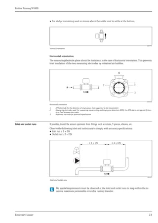
Performance characteristics
Reference operating
conditions
To DIN EN 29104
• Fluid temperature: (+28 ± 2) °C / (+82 ± 4) °F
• Ambient temperature range: (+22 ± 2) °C / (+72 ± 4) °F
• Warm-up period: 30 minutes
Installation conditions
• Inlet run > 10 × DN
• Outlet run > 5 × DN
• Sensor and transmitter grounded.
• The sensor is centered in the pipe.
The minimum conductivity information refers to measured value acquisition with the "CONT.PWR"
profile (continuous operation, the device records the maximum number of measured values, parameter
Prof., MPROF). Values can deviate if another profile is selected for measured value acquisition.
No special requirements must be observed at the inlet and outlet runs to keep within the in-
service maximum permissible errors for custody transfer.
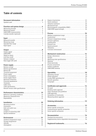
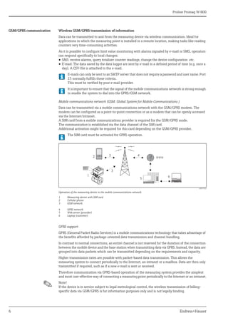
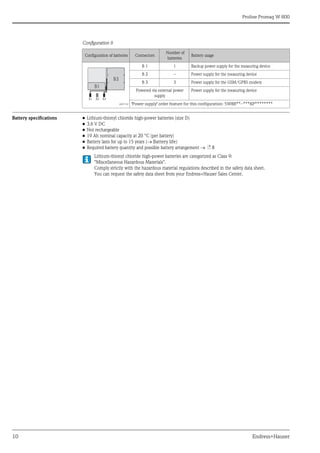
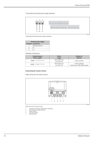
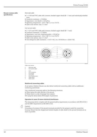
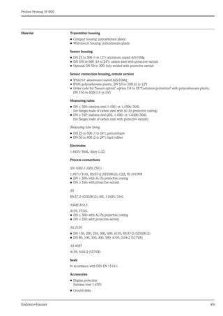
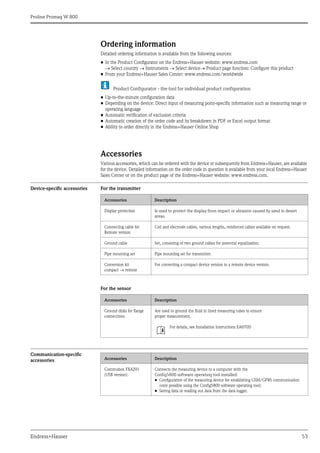
Maximum measured error Pulse output
±0.5% o.r. ± 2 mm/s (±0.5% o.r. ± 0.08 in/s)
o.r. = of reading
Fluctuations in the power supply do not have any effect within the specified range.
A0003200
Max. measured error in % of reading
Repeatability Max. ±0.2% o.r. ± 2.0 mm/s (±0.2% o.r. ± 0.08 in/s)
o.r. = of reading
2.5
[%]
2.0
1.5
1.0
0.5
0
0.5 %
0 1 2 4 6 8 10 [m/s]
v
5 10 15 20 25 30 32 [ft/s]
0](https://image.slidesharecdn.com/prolinepromagw800-endresshauserdatasheet-electromagneticflowmeter-210818172853/85/Proline-promag-w-800-endress-hauser-datasheet-electromagnetic-flowmeter-19-320.jpg)
![Proline Promag W 800
24 Endress+Hauser
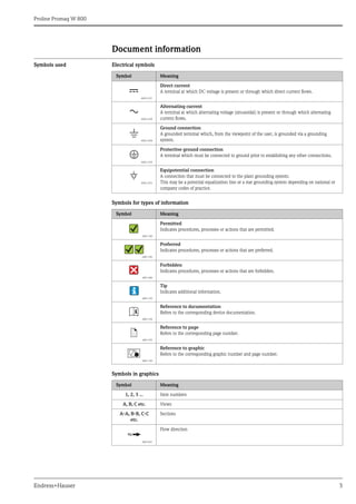
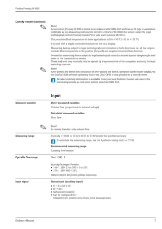
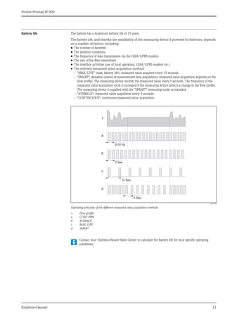
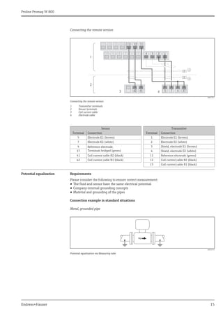
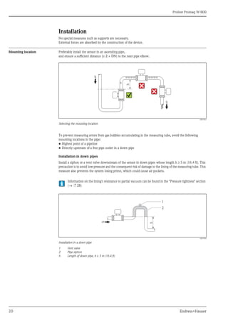
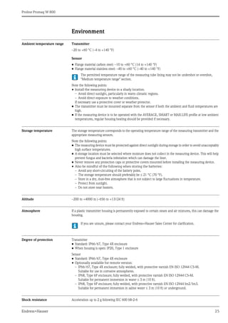
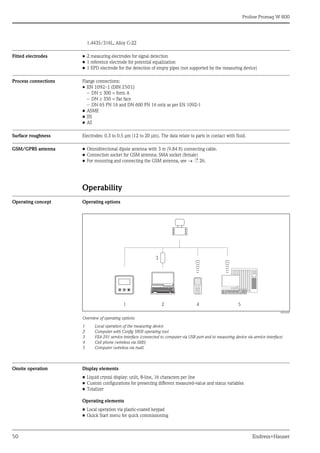
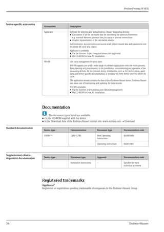
Adapters Suitable adapters to DIN EN 545 (double-flange reducers) can be used to install the sensor in larger-diameter
pipes.
The resultant increase in the rate of flow improves measuring accuracy with very slow-moving fluids. The
nomogram shown here can be used to calculate the pressure loss caused by reducers and expanders.
The nomogram only applies to liquids of viscosity similar to water.
Determining the pressure loss:
1. Calculate the ratio of the diameters d/D.
2. From the nomogram read off the pressure loss as a function of flow velocity (downstream from the
reduction) and the d/D ratio.
A0016359
Pressure loss due to adapters
Length of connecting cable The maximum connecting cable length is 20 m (35.6 ft).
When mounting the remote version, please note the following to achieve correct measuring results:
• Fix the cable run or route it in an armored conduit. Cable movements can falsify the measuring signal
especially in the case of low fluid conductivities.
• Route the cable well clear of electrical machines and switching elements.
• Ensure potential equalization between sensor and transmitter, if necessary.
Special installation Display protection
To ensure that the optional display protection can be easily opened, maintain the following minimum head
clearance: 350 mm (13.8 in)
100
10
0.5
d / D
[mbar]
0.6 0.7 0.8 0.9
1 m/s
2 m/s
3 m/s
4 m/s
5 m/s
6 m/s
7 m/s
8 m/s
1
D
d
max. 8°](https://image.slidesharecdn.com/prolinepromagw800-endresshauserdatasheet-electromagneticflowmeter-210818172853/85/Proline-promag-w-800-endress-hauser-datasheet-electromagnetic-flowmeter-24-320.jpg)
![Proline Promag W 800
26 Endress+Hauser
Vibration resistance Acceleration up to 2 g following IEC 600 68-2-6
Mechanical load Transmitter housing
• The transmitter housing must be protected against mechanical effects, such as shock, impact etc.
It is sometimes preferable to use the remote device version.
• The transmitter housing must never be used as a ladder or climbing aid!
Electromagnetic
compatibility (EMC)
In accordance with IEC/EN 61326
GSM/GPRS signal strength It is important to ensure that the signal of the mobile communications network is strong enough to enable the
system to dial into the GPRS/GSM network.
Process
Medium temperature range Sensor
The permissible temperature depends on the lining of the measuring tube.
• –20 to +50 °C (–4 to +122 °F) for polyurethane, DN 25 to 600 (1 to 24")
• 0 to +80 °C (+32 to +176 °F) for hard rubber, DN 50 to 600 (2 to 24")
Conductivity The minimum conductivity is 50 μS/cm.
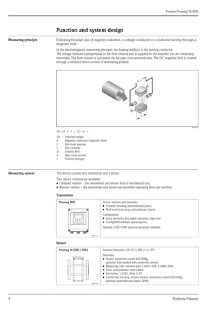
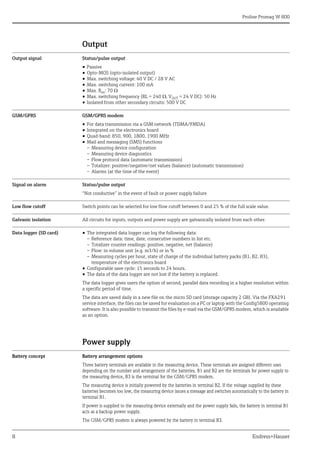
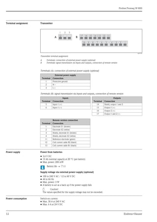
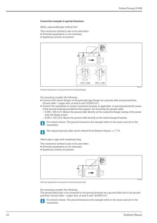
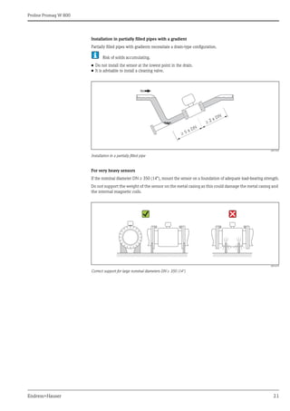
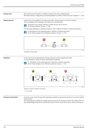
Pressure-temperature ratings The following material load diagrams refer to the entire device and not just the process connection.
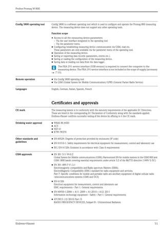
Flange connection according to EN 1092-1 (DIN 2501)
A0005594
PN 6/10/16/25/40, materials C22, FE 410W B and S235JRG2, DN 25 to 600 (1 to 24")
PN25
PN16
PN10
PN 6
PN40
0
5
10
15
20
25
35
30
40
[bar]
[psi]
-60 -40 -20 0 20 40 60 80 100 120 140 160 180 [°C]
360 [°F]
0
-40 100 200 300
200
100
400
300
500
600
0](https://image.slidesharecdn.com/prolinepromagw800-endresshauserdatasheet-electromagneticflowmeter-210818172853/85/Proline-promag-w-800-endress-hauser-datasheet-electromagnetic-flowmeter-26-320.jpg)
![Proline Promag W 800
Endress+Hauser 27
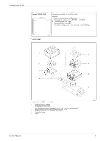
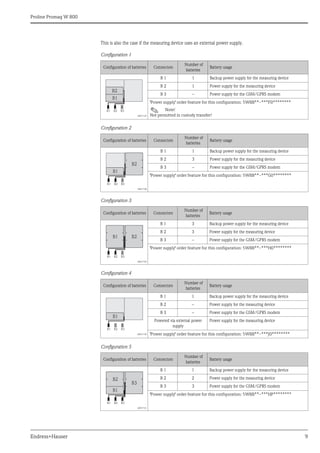
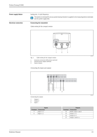
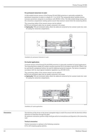
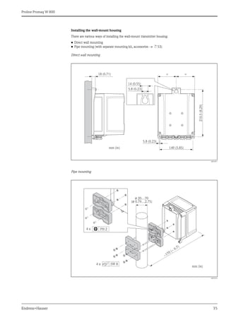
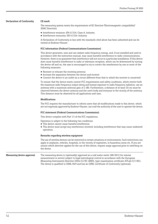
Flange connection according to EN 1092-1 (DIN 2501)
A0005304
PN 6/10/16/25/40, materials 1.4571/316L, DN 25 to 600 (1 to 24")
Flange connection according to ASME B16.5
A0003226
Class 150/300, materials A 105, DN 25 to 600 (1 to 24")
Flange connection according to ASME B16.5
A0005307
Class 150/300, materials F316L, DN 25 to 600 (1 to 24")
PN25
PN16
PN10
PN40
PN 6
0
5
10
15
20
25
35
30
40
[bar]
[psi]
-60 -40 -20 0 20 40 60 80 100 120 140 160 180 [°C]
360 [°F]
0
-40 100 200 300
200
100
400
300
500
600
0
Class300
Class150
0
10
20
30
40
50
[bar]
[psi]
-40 -20 0 20 40 60 80 100 120 140 160 180 [°C]
360 [°F]
0
-40 100 200 300
200
100
400
300
500
600
700
800
900
0
60
Class300
Class150
0
10
20
30
40
50
[bar]
[psi]
-40 -20 0 20 40 60 80 100 120 140 160 180 [°C]
360 [°F]
0
-40 100 200 300
200
100
400
300
500
600
700
800
900
0
60](https://image.slidesharecdn.com/prolinepromagw800-endresshauserdatasheet-electromagneticflowmeter-210818172853/85/Proline-promag-w-800-endress-hauser-datasheet-electromagnetic-flowmeter-27-320.jpg)
![Proline Promag W 800
28 Endress+Hauser
Flange connection according to JIS B2220
A0003228
10K/20K, materials HII, S235JRG2 and 1.0425/316L, DN 25 to 300 (1 to 12")
Flange connection according to AS 2129 and AS 4087
A0005595
Table E, materials A105, S235JRG2 and S275JR, DN 50 to 600 (2 to 48");
PN 16, materials A105, S275JR, DN 50 to 600 (2 to 48")
Pressure tightness Liner: polyurethane, hard rubber
Limiting flow The diameter of the pipe and the flow rate determine the nominal diameter of the sensor. The optimum velocity
of flow is between 2 and 3 m/s (6.56 to 9.84 ft/s). Also match the velocity of flow (v) to the physical properties
of the fluid:
• v < 2 m/s (v < 6.5 ft/s): for abrasive fluids (potter's clay, lime milk, ore slurry etc.)
• v > 2 m/s (v > 6.5 ft/s): for fluids producing buildup (wastewater sludge etc.)
10K
20K
-40 -20 0 20 40 60 80 100 120 140 160 180 [°C]
0
10
20
30
[bar]
360 [°F]
0
-40 100 200 300
[psi]
200
100
400
300
0
-40 -20 0 20 40 60 80 100 120 140 160 [°C]
0
10
5
20
15
[bar]
0
-40 100 200 300 [°F]
[psi]
200
100
300
0
TableE
PN16
Promag W
Nominal diameter
Measuring
tube liner
Liner pressure tightness: limit values for
absolute pressure at different fluid temperatures
[mm] [in]
25 °C (77 °F) 50 °C (122 °F) 80 °C (176 °F)
[mbar]/[psi] [mbar]/[psi] [mbar]/[psi]
25 to 600 1 to 24" Polyurethane 0 0 -
50 to 600 2 to 24" Hard rubber 0 0 0](https://image.slidesharecdn.com/prolinepromagw800-endresshauserdatasheet-electromagneticflowmeter-210818172853/85/Proline-promag-w-800-endress-hauser-datasheet-electromagnetic-flowmeter-28-320.jpg)
![Proline Promag W 800
Endress+Hauser 29
Flow characteristic values in SI units
Flow characteristic values in US units
Nominal
diameter
Recommended
flow
min./max. full scale value
Factory setting
Full scale value Pulse value
approx. 2 pulse/s
for
Low flow cut off
[mm] (v 0.5 or 10 m/s) (v 2.5 m/s) (v 2.5 m/s) (v 0.04 m/s)
25 15 to 295 dm³/min 75 dm3/min 0.03 dm3 2 dm3/min
32 25 to 485 dm³/min 125 dm3/min 0.05 dm3 4 dm3/min
40 40 to 755 dm³/min 200 dm3/min 0.08 dm3 6 dm3/min
50 60 to 1180 dm³/min 300 dm3/min 0.10 dm3 10 dm3/min
65 100 to 2000 dm³/min 500 dm3/min 0.20 dm3 15 dm3/min
80 150 to 3020 dm³/min 750 dm3/min 0.30 dm3 20 dm3/min
100 240 to 4750 dm³/min 1200 dm3/min 0.50 dm3 40 dm3/min
125 370 to 7400 dm³/min 1850 dm3/min 0.75 dm3 60 dm3/min
150 32 to 640 m³/h 150 m3/h 0.001 m3 5 m3/h
200 58 to 1135 m³/h 300 m3/h 0.002 m3 10 m3/h
250 90 to 1800 m³/h 500 m3/h 0.003 m3 15 m3/h
300 130 to 2500 m³/h 750 m3/h 0.004 m3 20 m3/h
350 175 to 3500 m³/h 1000 m3/h 0.006 m3 25 m3/h
375 200 to 4000 m³/h 1200 m3/h 0.008 m3 35 m3/h
400 226 to 4600 m³/h 1200 m3/h 0.008 m3 35 m3/h
450 286 to 5800 m³/h 1500 m3/h 0.010 m3 40 m3/h
500 353 to 7100 m³/h 2000 m3/h 0.012 m3 50 m3/h
600 510 to 10200 m³/h 2500 m3/h 0.017 m3 80 m3/h
Nominal
diameter
Recommended
flow
min./max. full scale value
Factory setting
Full scale value Pulse value
approx. 2 pulse/s
for
Low flow cut off
[in] (v 0.5 or 10 m/s) (v 2.5 m/s) (v 2.5 m/s) (v 0.04 m/s)
1" 4 to 80 gal/min 20 gal/min 0.008 gal 0.60 gal/min
– 7 to 130 gal/min 30 gal/min 0.015 gal 1.00 gal/min
1 /" 10 to 200 gal/min 50 gal/min 0.02 gal 1.50 gal/min
2" 16 to 320 gal/min 80 gal/min 0.03 gal 2.50 gal/min
2 ½" 28 to 530 gal/min 150 gal/min 0.05 gal 4.00 gal/min
3" 40 to 800 gal/min 200 gal/min 0.08 gal 6.00 gal/min
4" 65 to 1200 gal/min 300 gal/min 0.15 gal 10.0 gal/min
5" 100 to 1900 gal/min 500 gal/min 0.20 gal 15.0 gal/min
6" 142 to 2800 gal/min 700 gal/min 0.30 gal 20.0 gal/min
8" 250 to 4900 gal/min 1200 gal/min 0.50 gal 40.0 gal/min
10" 390 to 7700 gal/min 2000 gal/min 0.80 gal 60.0 gal/min
12" 570 to 11000 gal/min 3000 gal/min 1.15 gal 80.0 gal/min
14" 770 to 15000 gal/min 4000 gal/min 1.50 gal 115.0 gal/min
15" 880 to 17000 gal/min 5000 gal/min 2.00 gal 150.0 gal/min
16" 1000 to 19000 gal/min 5000 gal/min 2.00 gal 150.0 gal/min
18" 1265 to 25000 gal/min 6500 gal/min 2.50 gal 200.0 gal/min
20" 1600 to 30000 gal/min 7500 gal/min 3.00 gal 250.0 gal/min
24" 2250 to 44000 gal/min 12000 gal/min 5.00 gal 350.0 gal/min](https://image.slidesharecdn.com/prolinepromagw800-endresshauserdatasheet-electromagneticflowmeter-210818172853/85/Proline-promag-w-800-endress-hauser-datasheet-electromagnetic-flowmeter-29-320.jpg)
![Proline Promag W 800
Endress+Hauser 31
Mechanical construction
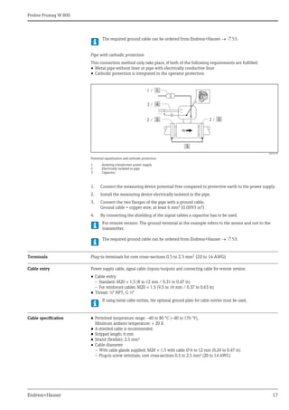
Design, dimensions Compact version DN 25 to 300 (1 to 12")
A0017392
Dimensions in SI units
Dimensions in US units
DN1)
L2)
A B C D E F G H J K
[mm] [mm] [mm] [mm] [mm] [mm] [mm] [mm] [mm] [mm] [mm] [mm]
25 200 216 189 120 165 157 269 353 84 94 182
32 200 216 189 120 165 157 269 353 84 94 182
40 200 216 189 120 165 157 269 353 84 94 182
50 200 216 189 120 165 157 269 353 84 94 182
65 200 216 189 180 165 157 294 403 109 94 182
80 200 216 189 180 165 157 294 403 109 94 182
100 250 216 189 180 165 157 294 403 109 94 182
125 250 216 189 260 165 157 334 484 150 140 182
150 300 216 189 260 165 157 334 484 150 140 182
200 350 216 189 324 165 157 359 539 180 156 182
250 450 216 189 400 165 157 384 589 205 156 182
300 500 216 189 460 165 157 409 639 230 166 182
1)
EN (DIN), AS, JIS: For flanges according to AS, only nominal diameters DN 80, 100 and 150 to 300 are available.
2) The length is independent of the selected pressure rating. Length in accordance with DVGW/ISO.
DN1) L2) A B C D E F G H J K
[in] [in] [in] [in] [in] [in] [in] [in] [in] [in] [in] [in]
1" 7.87 8.50 7.44 4.72 6.50 6.18 10.59 13.90 3.32 3.70 7.17
1½" 7.87 8.50 7.44 4.72 6.50 6.18 10.59 13.90 3.32 3.70 7.17
2" 7.87 8.50 7.44 4.72 6.50 6.18 10.59 13.90 3.32 3.70 7.17
3" 7.87 8.50 7.44 7.10 6.50 6.18 11.57 15.87 4.30 3.70 7.17
4" 9.84 8.50 7.44 7.10 6.50 6.18 11.57 15.87 4.30 3.70 7.17
6" 11.8 8.50 7.44 10.2 6.50 6.18 13.15 19.06 5.91 5.51 7.17
8" 13.8 8.50 7.44 12.8 6.50 6.18 14.13 21.22 7.10 6.14 7.17
10" 17.7 8.50 7.44 15.8 6.50 6.18 15.12 23.19 8.08 6.14 7.17
12" 19.7 8.50 7.44 18.1 6.50 6.18 16.10 25.16 9.06 6.54 7.17
1)
ASME
2) The length is independent of the selected pressure rating. Length in accordance with DVGW/ISO.
A
C
B
L
H
J
F
G
E
D
K](https://image.slidesharecdn.com/prolinepromagw800-endresshauserdatasheet-electromagneticflowmeter-210818172853/85/Proline-promag-w-800-endress-hauser-datasheet-electromagnetic-flowmeter-31-320.jpg)
![Proline Promag W 800
32 Endress+Hauser
Compact version DN 350 to 600 (14 to 24")
A0017394
Dimensions in SI units
Dimensions in US units
DN1)
L2)
A B C D E F G H J K
[mm] [mm] [mm] [mm] [mm] [mm] [mm] [mm] [mm] [mm] [mm] [mm]
350 550 216 189 564 165 157 478.5 760.5 282.0 276 192
375 600 216 189 616 165 157 504.5 812.5 308.0 276 192
400 600 216 189 616 165 157 504.5 812.5 308.0 276 192
450 650 216 189 666 165 157 529.5 862.5 333.0 292 192
500 650 216 189 717 165 157 555.0 913.5 358.5 292 192
600 780 216 189 821 165 157 607.0 1017.5 410.5 402 192
1)
EN (DIN), AS: For flanges according to AS, only nominal diameters DN 350, 400, 500 and 600 are available.
2)
The length is independent of the selected pressure rating. Length in accordance with DVGW/ISO.
DN1)
L2)
A B C D E F G H J K
[in] [in] [in] [in] [in] [in] [in] [in] [in] [in] [in] [in]
14" 21.6 8.50 7.44 22.2 6.50 6.18 18.84 29.94 11.1 10.9 7.56
15" 23.6 8.50 7.44 24.2 6.50 6.18 19.86 31.99 12.1 10.9 7.56
16" 23.6 8.50 7.44 24.2 6.50 6.18 19.86 31.99 12.1 10.9 7.56
18" 25.6 8.50 7.44 26.2 6.50 6.18 20.85 33.96 13.1 11.5 7.56
20" 25.6 8.50 7.44 28.2 6.50 6.18 21.85 35.96 14.1 11.5 7.56
24" 30.7 8.50 7.44 32.3 6.50 6.18 23.90 40.06 16.2 15.8 7.56
1)
ASME
2) The length is independent of the selected pressure rating. Length in accordance with DVGW/ISO.
L
C
E
F
J
G
A
B
H
D
K](https://image.slidesharecdn.com/prolinepromagw800-endresshauserdatasheet-electromagneticflowmeter-210818172853/85/Proline-promag-w-800-endress-hauser-datasheet-electromagnetic-flowmeter-32-320.jpg)
![Proline Promag W 800
Endress+Hauser 33
Compact version DN 350 to 600 (14 to 24")
Order code for "Design", option A "Insertion length short"
A0021031
Dimensions in SI units
Dimensions in US units
DN
[mm]
L
[mm]
A
[mm]
B
[mm]
D
[mm]
E
[mm]
F
[mm]
J
[mm]
K
[mm]
350 550 216 189 165 157 433 290 192
375 600 216 189 165 157 459 290 192
400 600 216 189 165 157 459 290 192
450 600 216 189 165 157 487 290 192
500 600 216 189 165 157 512 290 192
600 600 216 189 165 157 553 290 192
DN
[mm]
Dimension C Dimension G
EN (DIN) ASME AS EN (DIN) ASME AS
PN 6
[mm]
PN 10
[mm]
PN 16
[mm]
AWWA
[mm] [mm]
PN 6
[mm]
PN 10
[mm]
PN 16
[mm]
AWWA
[mm] [mm]
350 490 505 520 533 525 678 685 693 700 696
375 – – – – 550 – – – – 734
400 540 565 580 597 580 729 741 649 757 749
450 595 615 640 635 640 784 794 807 804 807
500 645 670 715 699 705 834 847 870 861 864
600 755 780 840 813 825 930 943 973 959 965
DN
[in]
L
[in]
A
[in]
B
[in]
D
[in]
E
[in]
F
[in]
J
[in]
K
[in]
14 21.6 8.50 7.44 6.50 6.18 17.1 11.4 7.56
15 23.6 8.50 7.44 6.50 6.18 18.1 11.4 7.56
16 23.6 8.50 7.44 6.50 6.18 18.1 11.4 7.56
18 23.6 8.50 7.44 6.50 6.18 19.2 11.4 7.56
20 23.6 8.50 7.44 6.50 6.18 20.2 11.4 7.56
24 23.6 8.50 7.44 6.50 6.18 21.8 11.4 7.56
L
C
E
F
J
G
A
B
D
K](https://image.slidesharecdn.com/prolinepromagw800-endresshauserdatasheet-electromagneticflowmeter-210818172853/85/Proline-promag-w-800-endress-hauser-datasheet-electromagnetic-flowmeter-33-320.jpg)
![Proline Promag W 800
34 Endress+Hauser
Transmitter remote version, wall-mount housing
"Housing" order feature, option N: remote, polycarbonate
A0017347
Dimensions in SI units
Dimensions in US units
DN
[in]
Dimension C Dimension G
EN (DIN) ASME AS EN (DIN) ASME AS
PN 6
[in]
PN 10
[in]
PN 16
[in]
AWWA
[in] [in]
PN 6
[in]
PN 10
[in]
PN 16
[in]
AWWA
[in] [in]
14 19.3 19.9 20.5 21.0 20.7 26.7 27.0 27.3 27.6 27.4
15 – – – – 21.7 – – – – 28.9
16 21.3 22.2 22.8 23.5 22.8 28.7 29.2 29.5 29.8 29.5
18 23.4 24.2 25.2 25.0 25.2 30.9 31.3 31.8 31.7 31.8
20 25.4 26.4 28.1 27.5 27.8 32.9 33.4 34.3 33.9 34.0
24 29.7 30.7 33.1 32.0 32.5 36.6 37.2 38.3 37.8 38.0
A B C D E F G H J K L
[mm] [mm] [mm] [mm] [mm] [mm] [mm] [mm] [mm] [mm] [mm]
165 185 15 25 225 151.5 50 53 56 88.5 53
A B C D E F G H J K L
[in] [in] [in] [in] [in] [in] [in] [in] [in] [in] [in]
6.50 7.28 0.59 0.98 8.86 5.96 1.97 2.09 2.20 3.48 2.09
B
A
K
G
H
L
J
J
C
D
E
F](https://image.slidesharecdn.com/prolinepromagw800-endresshauserdatasheet-electromagneticflowmeter-210818172853/85/Proline-promag-w-800-endress-hauser-datasheet-electromagnetic-flowmeter-34-320.jpg)
![Proline Promag W 800
36 Endress+Hauser
Remote version sensor, DN 25 to 300 (1 to 12")
A0012462
Dimensions in SI units
Dimensions in US units
DN1)
L2)
A B C D E F G H J
[mm] [mm] [mm] [mm] [mm] [mm] [mm] [mm] [mm] [mm] [mm]
25 200
129 163 143 102
286 202 84 120 94
32 200 286 202 84 120 94
40 200 286 202 84 120 94
50 200 286 202 84 120 94
65 200 336 227 109 180 94
80 200 336 227 109 180 94
100 250 336 227 109 180 94
125 250 417 267 150 260 140
150 300 417 267 150 260 140
200 350 472 292 180 324 156
250 450 522 317 205 400 156
300 500 572 342 230 460 166
1)
EN (DIN), AS, JIS: For flanges according to AS, only nominal diameters DN 80, 100 and 150 to 300 are available.
2)
The length is independent of the selected pressure rating. Length in accordance with DVGW/ISO.
DN1)
L2)
A B C D E F G H J
[in] [in] [in] [in] [in] [in] [in] [in] [in] [in] [in]
1" 7.87
5.08 6.42 5.63 4.02
11.3 7.95 3.32 4.72 3.70
1½" 7.87 11.3 7.95 3.32 4.72 3.70
2" 7.87 11.3 7.95 3.32 4.72 3.70
3" 7.87 13.2 8.94 4.30 7.10 3.70
4" 9.84 13.2 8.94 4.30 7.10 3.70
6" 11.8 16.4 10.5 5.91 10.2 5.51
8" 13.8 18.6 11.5 7.10 12.8 6.14
10" 17.7 20.6 12.5 8.08 15.8 6.14
12" 19.7 22.5 13.5 9.06 18.1 6.54
1)
ASME
2) The length is independent of the selected pressure rating. Length in accordance with DVGW/ISO.
J
L
E
G
F
H
B
C
A
D](https://image.slidesharecdn.com/prolinepromagw800-endresshauserdatasheet-electromagneticflowmeter-210818172853/85/Proline-promag-w-800-endress-hauser-datasheet-electromagnetic-flowmeter-36-320.jpg)
![Proline Promag W 800
Endress+Hauser 37
Remote version sensor, DN 50 to 300 (2 to 12"), fully welded (IP68)
A0017206
Dimensions in SI units
DN L A B D F
[mm] [mm] [mm] [mm] [mm] [mm]
50 200
112 138 95.5
189.0
65 200 201.5
80 200 206.5
100 250 219.0
125 250 232.0
150 300 253.5
200 350 279.0
250 450 312.5
300 500 337.5
DN E for pressure ratings
EN (DIN) ASME AS JIS
PN 10 PN 16 PN 25 PN 40 Class
150
Class
300
Table E PN 16 10K 20K
[mm] [mm] [mm] [mm] [mm] [mm] [mm] [mm] [mm] [mm] [mm]
50 – – – 272 265 272 264 264 267 267
65 – 295 – 295 – – – – 290 290
80 – 307 – 307 302 311 300 300 300 307
100 – 330 – 382 333 346 327 327 325 332
125 – 357 – 367 – – – – 357 367
150 – 396 – 404 393 412 395 395 395 406
200 450 450 460 – 450 – 447 447 445 454
250 510 515 525 – 516 – 515 515 513 528
300 560 568 580 – 580 – 565 565 560 578
DN H for pressure ratings
EN (DIN) ASME AS JIS
PN 10 PN 16 PN 25 PN 40 Class
150
Class
300
Table E PN 16 10K 20K
[mm] [mm] [mm] [mm] [mm] [mm] [mm] [mm] [mm] [mm] [mm]
50 – – – 165 152.4 165.0 150 150 155 155
65 – 185 – 185 – – – – 175 175
80 – 200 – 200 190.5 209.6 185 185 185 200
100 – 220 – 325 228.6 254.0 215 215 210 225
125 – 250 – 270 – – – – 250 270
H
B
A
D
L
F
E](https://image.slidesharecdn.com/prolinepromagw800-endresshauserdatasheet-electromagneticflowmeter-210818172853/85/Proline-promag-w-800-endress-hauser-datasheet-electromagnetic-flowmeter-37-320.jpg)
![Proline Promag W 800
38 Endress+Hauser
Dimensions in US units
150 – 285 – 300 279.4 317.5 280 280 280 305
200 340 340 360 – 342.9 – 335 335 330 350
250 395 405 425 – 406.4 – 405 405 400 430
300 445 460 485 – 482.6 – 455 455 445 480
DN L A B D F
[in] [in] [in] [in] [in] [in]
2" 7.78
4.41 5.43 3.76
7.44
3" 7.78 8.13
4" 9.84 8.62
6" 11.8 9.98
8" 13.8 11.0
10" 17.7 12.3
12" 19.7 13.3
DN E for pressure ratings
EN (DIN) ASME AS JIS
PN 10 PN 16 PN 25 PN 40 Class
150
Class
300
Table E PN 16 10K 20K
[in] [in] [in] [in] [in] [in] [in] [in] [in] [in] [in]
2" – – – 10.69 10.44 10.69 10.39 10.39 10.49 10.49
3" – 12.07 – 12.07 11.88 12.26 11.81 11.81 11.81 12.07
4" – 12.99 – 15.02 13.12 13.62 12.85 12.85 12.80 13.05
6" – 15.59 – 15.89 15.48 16.23 15.55 15.55 15.55 15.98
8" 17.72 17.72 18.11 – 17.73 – 17.58 17.58 17.52 17.87
10" 20.08 20.28 20.67 – 20.30 – 20.28 20.28 20.18 20.77
12" 22.05 22.34 22.83 – 22.83 – 22.24 22.24 22.05 22.74
DN H for pressure ratings
EN (DIN) ASME AS JIS
PN 10 PN 16 PN 25 PN 40 Class
150
Class
300
Table E PN 16 10K 20K
[in] [in] [in] [in] [in] [in] [in] [in] [in] [in] [in]
2" – – – 6.50 6.00 6.50 5.91 5.91 6.10 6.10
3" – 7.78 – 7.78 7.50 8.25 7.28 7.28 7.28 7.78
4" – 8.66 – 12.8 9.00 10.0 8.46 8.46 8.27 8.86
6" – 11.2 – 11.8 11.0 12.5 11.0 11.0 11.0 12.0
8" 13.4 13.4 14.2 – 13.5 – 13.2 13.2 13.0 13.8
10" 15.6 15.9 16.7 – 16.0 – 15.9 15.9 15.8 16.9
12" 17.5 18.1 19.1 – 19.0 – 17.9 17.9 17.5 18.9
DN H for pressure ratings
EN (DIN) ASME AS JIS
PN 10 PN 16 PN 25 PN 40 Class
150
Class
300
Table E PN 16 10K 20K
[mm] [mm] [mm] [mm] [mm] [mm] [mm] [mm] [mm] [mm] [mm]](https://image.slidesharecdn.com/prolinepromagw800-endresshauserdatasheet-electromagneticflowmeter-210818172853/85/Proline-promag-w-800-endress-hauser-datasheet-electromagnetic-flowmeter-38-320.jpg)
![Proline Promag W 800
Endress+Hauser 39
Remote version sensor, DN 350 to 600 (14 to 24")
A0003220
Dimensions in SI units
Dimensions in US units
DN1) L2) A B C D E F G H J
[mm] [mm] [mm] [mm] [mm] [mm] [mm] [mm] [mm] [mm] [mm]
350 550
129 163 143 102
683.5 401.5 282.0 564 276
375 600 735.5 427.5 308.0 616 276
400 600 735.5 427.5 308.0 616 276
450 650 785.5 452.5 333.0 666 292
500 650 836.5 478.0 358.5 717 292
600 780 940.5 530.0 410.5 821 402
1) EN (DIN), AS: For flanges according to AS, only nominal diameters DN 350, 400, 500 and 600 are available.
2)
The length is independent of the selected pressure rating. Length in accordance with DVGW/ISO.
DN1)
L2)
A B C D E F G H J
[mm] [mm] [mm] [mm] [mm] [mm] [mm] [mm] [mm] [mm] [mm]
14" 21.6
5.08 6.42 5.63 4.02
29.1 15.8 11.1 22.2 10.9
15" 23.6 31.1 16.8 12.1 24.2 10.9
16" 23.6 31.1 16.8 12.1 24.2 10.9
18" 25.6 33.1 17.8 13.1 26.2 11.5
20" 25.6 35.1 18.8 14.1 28.2 11.5
24" 30.7 39.1 20.9 16.2 32.3 15.8
1)
ASME
2) The length is independent of the selected pressure rating. Length in accordance with DVGW/ISO.
H
E
G
F
L
J
A B
C
D](https://image.slidesharecdn.com/prolinepromagw800-endresshauserdatasheet-electromagneticflowmeter-210818172853/85/Proline-promag-w-800-endress-hauser-datasheet-electromagnetic-flowmeter-39-320.jpg)
![Proline Promag W 800
40 Endress+Hauser
Remote version sensor, DN 350 to 600 (14 to 24")
Order code for "Design", option A "Insertion length short"
A0017284
Dimensions in SI units
Dimensions in US units
DN
[mm]
A
[mm]
B
[mm]
E
[mm]
F
[mm]
350 129 353 290 550
375 129 379 290 600
400 129 379 290 600
450 129 407 290 600
500 129 432 290 600
600 129 473 290 600
DN
[mm]
Dimension C Dimension D
EN (DIN) ASME AS EN (DIN) ASME AS
PN 6
[mm]
PN 10
[mm]
PN 16
[mm]
AWWA
[mm] [mm]
PN 6
[mm]
PN 10
[mm]
PN 16
[mm]
AWWA
[mm] [mm]
350 598 605 613 620 615 490 505 520 533 525
375 – – – – 654 – – – – 550
400 649 661 669 677 669 540 565 580 597 580
450 704 714 727 724 727 595 615 640 635 640
500 754 767 790 781 784 645 670 715 699 705
600 850 863 893 879 885 755 780 840 813 825
DN
[in]
A
[in]
B
[in]
E
[in]
F
[in]
14 5.08 13.9 11.4 21.6
15 5.08 14.9 11.4 23.6
16 5.08 14.9 11.4 23.6
18 5.08 16.0 11.4 23.6
20 5.08 17.0 11.4 23.6
24 5.08 18.6 11.4 23.6
D F
E
B
C
A](https://image.slidesharecdn.com/prolinepromagw800-endresshauserdatasheet-electromagneticflowmeter-210818172853/85/Proline-promag-w-800-endress-hauser-datasheet-electromagnetic-flowmeter-40-320.jpg)
![Proline Promag W 800
Endress+Hauser 41
Remote version sensor, DN 350 to 600 (14 to 24")
Order code for "Design", option A "Insertion length short"
Order code for "Sensor option", option CA to CE "Corrosion protection"
A0020962
Dimensions in SI units
DN
[in]
Dimension C Dimension D
EN (DIN) ASME AS EN (DIN) ASME AS
PN 6
[in]
PN 10
[in]
PN 16
[in]
AWWA
[in] [in]
PN 6
[in]
PN 10
[in]
PN 16
[in]
AWWA
[in] [in]
14 23.5 23.8 24.1 24.4 24.2 19.3 19.9 20.5 21.0 20.7
15 – – – – 25.7 – – – – 21.7
16 25.6 26.0 26.3 26.7 26.3 21.3 22.2 22.8 23.5 22.8
18 27.7 28.1 28.6 28.5 28.6 23.4 24.2 25.2 25.0 25.2
20 29.7 30.2 31.1 30.7 30.9 25.4 26.4 28.1 27.5 27.8
24 33.5 34.0 35.2 34.6 34.8 29.7 30.7 33.1 32.0 32.5
DN
[mm]
A
[mm]
B
[mm]
E
[mm]
F
[mm]
350 112 350 290 550
375 112 376 290 600
400 112 376 290 600
450 112 403 290 600
500 112 428 290 600
600 112 478 290 600
DN
[mm]
Dimension C Dimension D
EN (DIN) AWWA AS EN (DIN) AWWA AS
PN 6
[mm]
PN 10
[mm]
PN 16
[mm] [mm] [mm]
PN 6
[mm]
PN 10
[mm]
PN 16
[mm] [mm] [mm]
350 595 603 610 – 613 490 505 520 – 525
375 – – – – 651 – – – – 550
400 646 659 666 – 666 540 565 580 – 580
450 701 711 723 – 723 595 615 640 – 640
D F
E
B
C
A](https://image.slidesharecdn.com/prolinepromagw800-endresshauserdatasheet-electromagneticflowmeter-210818172853/85/Proline-promag-w-800-endress-hauser-datasheet-electromagnetic-flowmeter-41-320.jpg)
![Proline Promag W 800
42 Endress+Hauser
Dimensions in US units
500 751 763 786 – 781 645 670 715 – 705
600 856 868 898 – 891 755 780 840 – 825
DN
[in]
A
[in]
B
[in]
E
[in]
F
[in]
14 4.41 13.8 11.4 21.6
15 4.41 14.8 11.4 23.6
16 4.41 14.8 11.4 23.6
18 4.41 15.9 11.4 23.6
20 4.41 16.9 11.4 23.6
24 4.41 18.8 11.4 23.6
DN
[in]
Dimension C Dimension D
EN (DIN) AWWA AS EN (DIN) AWWA AS
PN 6
[in]
PN 10
[in]
PN 16
[in] [in] [in]
PN 6
[in]
PN 10
[in]
PN 16
[in] [in] [in]
14 23.4 23.7 24.0 – 24.1 19.3 19.9 20.5 – 20.7
15 – – – – 25.6 – – – – 21.7
16 25.4 25.9 26.2 – 26.2 21.3 22.2 22.8 – 22.8
18 27.6 28.0 28.5 – 28.5 23.4 24.2 25.2 – 25.2
20 29.6 30.0 30.9 – 30.7 25.4 26.4 28.1 – 27.8
24 33.7 34.2 35.4 – 35.1 29.7 30.7 33.1 – 32.5
DN
[mm]
Dimension C Dimension D
EN (DIN) AWWA AS EN (DIN) AWWA AS
PN 6
[mm]
PN 10
[mm]
PN 16
[mm] [mm] [mm]
PN 6
[mm]
PN 10
[mm]
PN 16
[mm] [mm] [mm]](https://image.slidesharecdn.com/prolinepromagw800-endresshauserdatasheet-electromagneticflowmeter-210818172853/85/Proline-promag-w-800-endress-hauser-datasheet-electromagnetic-flowmeter-42-320.jpg)
![Proline Promag W 800
Endress+Hauser 43
Remote version sensor, DN 350 to 600 (14 to 24")
Order code for "Design", option B "Insertion length long"
Order code for "Sensor option", option CA to CE "Corrosion protection"
A0018158
Dimensions in SI units
Dimensions in US units
DN
[mm]
L
[mm]
A
[mm]
B
[mm]
C
[mm]
D
[mm]
E
[mm]
F
[mm]
G
[mm]
H
[mm]
350 550 112 564 138 95,5 395 282 677 276
375 600 112 616 138 95,5 421 308 729 276
400 600 112 616 138 95,5 421 308 729 276
450 650 112 666 138 95,5 446 333 779 292
500 650 112 717 138 95,5 472 359 830 292
600 780 112 821 138 95,5 524 411 934 402
DN
[in]
L
[in]
A
[in]
B
[in]
C
[in]
D
[in]
E
[in]
F
[in]
G
[in]
H
[in]
14 21.6 4.41 22.2 5.43 3.76 15.6 11.1 26.7 10.9
15 23.6 4.41 24.2 5.43 3.76 16.6 12.1 28.7 10.9
16 23.6 4.41 24.2 5.43 3.76 16.6 12.1 28.7 10.9
18 25.6 4.41 26.2 5.43 3.76 17.6 13.1 30.7 11.5
20 25.6 4.41 28.2 5.43 3.76 18.6 14.1 32.7 11.5
24 30.7 4.41 32.3 5.43 3.76 20.6 16.2 36.8 15.8
L
H
G
E
B
A C
D
F](https://image.slidesharecdn.com/prolinepromagw800-endresshauserdatasheet-electromagneticflowmeter-210818172853/85/Proline-promag-w-800-endress-hauser-datasheet-electromagnetic-flowmeter-43-320.jpg)
![Proline Promag W 800
44 Endress+Hauser
Accessories
Ground disks for flange connections
A0017303
Dimensions in SI units
DN 1) EN (DIN) / JIS / AS 2)
A B D H
[mm] [mm] [mm] [mm] [mm]
25 26 62 77.5 87.5
32 35 80 87.5 94.5
40 41 82 101.0 103
50 52 101 115.5 108
65 68 121 131.5 118
80 80 131 154.5 135
100 104 156 186.5 153
125 130 187 206.5 160
150 158 217 256 184
200 206 267 288 205
250 260 328 359 240
300 3) 312 375 413 273
300 4) 310 375 404 268
350 3) 343 433 479 365
375 3) 343 433 479 365
400 3) 393 480 542 395
450 3) 439 538 583 417
500 3) 493 592 650 460
600 3)
593 693 766 522
1)
Ground disks can be used for all the flange standards/pressure ratings which can be supplied in the standard version.
2) EN (DIN), AS, JIS; For flanges according to AS, DN 32, 40, 65 and 125 are not available.
3)
PN 10/16
4)
PN 25, JIS 10K/20K
H
H
DN£ 300 (12")
t = 2 (0.08)
t = 2 (0.08)
9 (0.35)
Æ
6.5 (0.26)
Æ
B
Æ
A
Æ D
Æ
A
Æ
B
Æ
D
Æ
³
DN 350 (14")](https://image.slidesharecdn.com/prolinepromagw800-endresshauserdatasheet-electromagneticflowmeter-210818172853/85/Proline-promag-w-800-endress-hauser-datasheet-electromagnetic-flowmeter-44-320.jpg)
![Proline Promag W 800
Endress+Hauser 45
Dimensions in US units
Weight Weight in SI units
Promag W (standard)
DN1) ASME
A B D H
[in] [in] [in] [in] [in]
1" 1.02 2.44 3.05 3.44
1 ½" 1.61 3.23 3.98 4.06
2" 2.05 3.98 4.55 4.25
3" 3.15 5.16 6.08 5.31
4" 4.09 6.14 7.34 6.02
6" 6.22 8.54 10.08 7.24
8" 8.11 10.51 11.34 8.07
10" 10.24 12.91 14.13 9.45
12" 12.28 14.76 16.26 10.75
14" 13.50 17.05 18.86 14.37
15" 13.50 17.05 18.86 14.37
16" 15.47 18.90 21.34 15.55
18" 17.28 21.18 22.95 16.42
20" 19.41 23.31 25.59 18.11
24" 23.35 27.28 30.16 20.55
1) Ground disks can be used for all the flange standards/pressure ratings which can be supplied in the standard version.
Weight data of Promag W in kg (for standard pressure ratings and excluding packaging material)
Nominal
diameter
Compact version
(sensor and transmitter)
excluding batteries
Remote version
(sensor and connection housing)
excluding connecting cable, transmitter and
batteries
[mm] [in] EN (DIN) /AS* JIS ASME EN (DIN) /AS* JIS ASME
25 1"
PN
40
5.3
10K
5.3
Class
150
5.3
PN
40
5.3
10K
5.3
Class
150
5.3
32 – 6.0 5.3 – 6.0 5.3 –
40 1 ½" 7.4 6.3 7.4 7.4 6.3 7.4
50 2" 8.6 7.3 8.6 8.6 7.3 8.6
65 –
PN
16
10.0 9.1 –
PN
16
10.0 9.1 –
80 3" 12.0 10.5 12.0 12.0 10.5 12.0
100 4" 14.0 12.7 14.0 14.0 12.7 14.0
125 – 19.5 19.0 – 19.5 19.0 –
150 6" 23.5 22.5 23.5 23.5 22.5 23.5
200 8"
PN
10
43 39.9 43
PN
10
43 39.9 43
250 10" 63 67.4 63 63 67.4 73
300 12" 68 70.3 108 68 70.3 108
350 14" 113 173 113 173
400 16" 133 203 133 203
450 18" 173 253 173 253
500 20" 173 283 173 283
600 24" 233 403 233 403
Transmitter remote version = 1.5 kg
*Flanges according to AS are only available for DN 80, 100, 150 to 400, 500 and 600
Weight of battery block with: one battery = 100 g/two batteries = 190 g/three batteries = 290 g](https://image.slidesharecdn.com/prolinepromagw800-endresshauserdatasheet-electromagneticflowmeter-210818172853/85/Proline-promag-w-800-endress-hauser-datasheet-electromagnetic-flowmeter-45-320.jpg)
![Proline Promag W 800
46 Endress+Hauser
Promag W (fully welded sensor option)
Order code for "Design", option A "Insertion length short" with DN 350 to 600
Order code for "Design", option A "Insertion length short" with DN 350 to 600
Weight data of Promag W in kg (for standard pressure ratings and excluding packaging material)
Nominal
diameter
Remote version (sensor and connection housing)
excluding connecting cable, transmitter and batteries
[mm] [in] EN (DIN) /AS* JIS ASME
50 2" PN 40 10
10
K
9
Class
150
9
65 –
PN
16
11 10 –
80 3" 13 11 13
100 4" 15 13 17
125 – 20 18 –
150 6" 25 23 26
200 8"
PN
10
36 32 42
250 10" 49 48 59
300 12" 58 55 84
Transmitter remote version = 1.5 kg
*Flanges according to AS are only available for DN 50, 80, 100, 150, 200, 250 and 300.
Weight of battery block with: one battery = 100 g/two batteries = 190 g/three batteries = 290 g
Weight data of Promag W in kg (for standard pressure ratings and excluding packaging material)
Compact version (sensor and transmitter) excluding batteries
DN EN (DIN) ASME, AWWA AS
[mm] [in]
Pres-
sure
rating
[kg]
Pres-
sure
rating
[kg]
Pres-
sure
rating
[kg]
Pressure
rating [kg]
Pres-
sure
rating
[kg]
Pres-
sure
rating
[kg]
350 14 PN 6 79 PN 10 90 PN 16 105 Class 150 139 PN 16 101 Table E 101
375 15 PN 6 – PN 10 – PN 16 – Class 150 – PN 16 107 Table E –
400 16 PN 6 91 PN 10 106 PN 16 123 Class 150 170 PN 16 122 Table E 122
450 18 PN 6 101 PN 10 114 PN 16 140 Class 150 193 PN 16 135 Table E 145
500 20 PN 6 116 PN 10 134 PN 16 180 Class 150 230 PN 16 184 Table E 184
600 24 PN 6 157 PN 10 164 PN 16 225 Class 150 304 PN 16 262 Table E 262
Weight data of Promag W in kg (for standard pressure ratings and excluding packaging material)
Remote version (sensor and connection housing) excluding connecting cable, transmitter and batteries
DN EN (DIN) ASME, AWWA AS
[mm] [in]
Pres-
sure
rating
[kg]
Pres-
sure
rating
[kg]
Pres-
sure
rating
[kg]
Pressure
rating [kg]
Pres-
sure
rating
[kg]
Pres-
sure
rating
[kg]
350 14 PN 6 76 PN 10 87 PN 16 105 Class 150 136 PN 16 98 Table E 98
375 15 PN 6 – PN 10 – PN 16 – Class 150 – PN 16 104 Table E –
400 16 PN 6 88 PN 10 103 PN 16 123 Class 150 167 PN 16 119 Table E 119
450 18 PN 6 98 PN 10 111 PN 16 140 Class 150 190 PN 16 132 Table E 142
500 20 PN 6 113 PN 10 131 PN 16 180 Class 150 227 PN 16 181 Table E 181
600 24 PN 6 154 PN 10 161 PN 16 225 Class 150 301 PN 16 259 Table E 259](https://image.slidesharecdn.com/prolinepromagw800-endresshauserdatasheet-electromagneticflowmeter-210818172853/85/Proline-promag-w-800-endress-hauser-datasheet-electromagnetic-flowmeter-46-320.jpg)
![Proline Promag W 800
Endress+Hauser 47
Weight in US units
Promag W (standard)
Promag W (fully welded sensor option)
Weight data of Promag W in lbs (excluding packaging material)
Nominal
diameter
Compact version
(sensor and transmitter)
excluding batteries
Remote version
(sensor and connection housing)
excluding connecting cable, transmitter and
batteries
[mm] [in] ASME ASME
25 1"
Class
150
11.7
Class
150
11.7
32 – – –
40 1 ½" 16.3 16.3
50 2" 19.0 19.0
65 – – –
80 3" 26.5 26.5
100 4" 30.9 30.9
125 – – –
150 6" 51.8 51.8
200 8" 94.8 94.8
250 10" 139 161
300 12" 238 238
350 14" 382 382
400 16" 448 448
450 18" 558 558
500 20" 624 624
600 24" 889 889
Transmitter remote version = 3.3 lbs
Weight of battery block with: one battery = 3.53 oz/two batteries = 6.7 oz/three batteries = 10.2 oz
Weight data of Promag W in lbs (for standard pressure ratings and excluding packaging material)
Nominal
diameter
Remote version (sensor and connection housing)
excluding connecting cable, transmitter and batteries
[mm] [in] ASME
50 2"
Class
150
19.9
65 – –
80 3" 28.7
100 4" 37.5
125 – –
150 6" 57.3
200 8" 92.6
250 10" 130
300 12" 185
Transmitter remote version = 3.3 lbs
Weight of battery block with: one battery = 3.53 oz/two batteries = 6.7 oz/three batteries = 10.2 oz](https://image.slidesharecdn.com/prolinepromagw800-endresshauserdatasheet-electromagneticflowmeter-210818172853/85/Proline-promag-w-800-endress-hauser-datasheet-electromagnetic-flowmeter-47-320.jpg)
![Proline Promag W 800
48 Endress+Hauser
Order code for "Design", option A "Insertion length short" with DN 14 to 24"
Order code for "Design", option A "Insertion length short" with DN 14 to 24"
Measuring tube specifications
Weight data of Promag W in lbs (for standard pressure ratings and excluding packaging material)
Compact version (sensor and transmitter) excluding batteries
DN ASME, AWWA
[mm] [in] Pressure rating [lbs]
350 14 Class 150 306
375 15 Class 150 –
400 16 Class 150 375
450 18 Class 150 425
500 20 Class 150 507
600 24 Class 150 670
Weight data of Promag W in kg (for standard pressure ratings and excluding packaging material)
Remote version (sensor and connection housing) excluding connecting cable, transmitter and batteries
DN ASME, AWWA
[mm] [in] Pressure rating [lbs]
350 14 Class 150 301
375 15 Class 150 –
400 16 Class 150 369
450 18 Class 150 420
500 20 Class 150 501
600 24 Class 150 664
Nominal
diameter
Pressure rating Measuring tube internal diameter
EN (DIN) AS 2129 AS 4087 ASME JIS Hard rubber Polyurethane
[mm] [in] [mm] [in] [mm] [in]
25 1" PN 40 – – Class 150 20K – – 24 0.94
32 – PN 40 – – – 20K – – 32 1.26
40 1 ½" PN 40 – – Class 150 20K – – 38 1.50
50 2" PN 40 Table E PN16 Class 150 10K 50 1.97 50 1.97
65 – PN 16 – – – 10K 66 2.60 66 2.60
80 3" PN 16 Table E PN16 Class 150 10K 79 3.11 79 3.11
100 4" PN 16 Table E PN16 Class 150 10K 102 4.02 102 4.02
125 – PN 16 – – – 10K 127 5.00 127 5.00
150 6" PN 10 Table E PN16 Class 150 10K 156 6.14 156 6.14
200 8" PN 10 Table E PN16 Class 150 10K 204 8.03 204 8.03
250 10" PN 10 Table E PN16 Class 150 10K 258 10.2 258 10.2
300 12" PN 10 Table E PN16 Class 150 10K 309 12.2 309 12.2
350 14" PN 6 Table E PN16 Class 150 – 342 13.5 342 13.5
375 15" – – PN16 – – 392 15.4 392 15.4
400 16" PN 6 Table E PN16 Class 150 – 392 15.4 392 15.4
450 18" PN 6 – – Class 150 – 437 17.2 437 17.2
500 20" PN 6 Table E PN16 Class 150 – 492 19.4 492 19.4
600 24" PN 6 Table E PN16 Class 150 – 594 23.4 594 23.4](https://image.slidesharecdn.com/prolinepromagw800-endresshauserdatasheet-electromagneticflowmeter-210818172853/85/Proline-promag-w-800-endress-hauser-datasheet-electromagnetic-flowmeter-48-320.jpg)


The document provides technical information on the Proline ProMag W 800 electromagnetic flowmeter, which is designed for demanding water and wastewater applications. It highlights features such as long battery life, maintenance-free operation, and a robust sensor with corrosion protection. Additionally, it outlines communication capabilities and compliance with international standards for custody transfer and drinking water approval.


