
Download to read offline
![Proline Promag L 800
18 Endress+Hauser
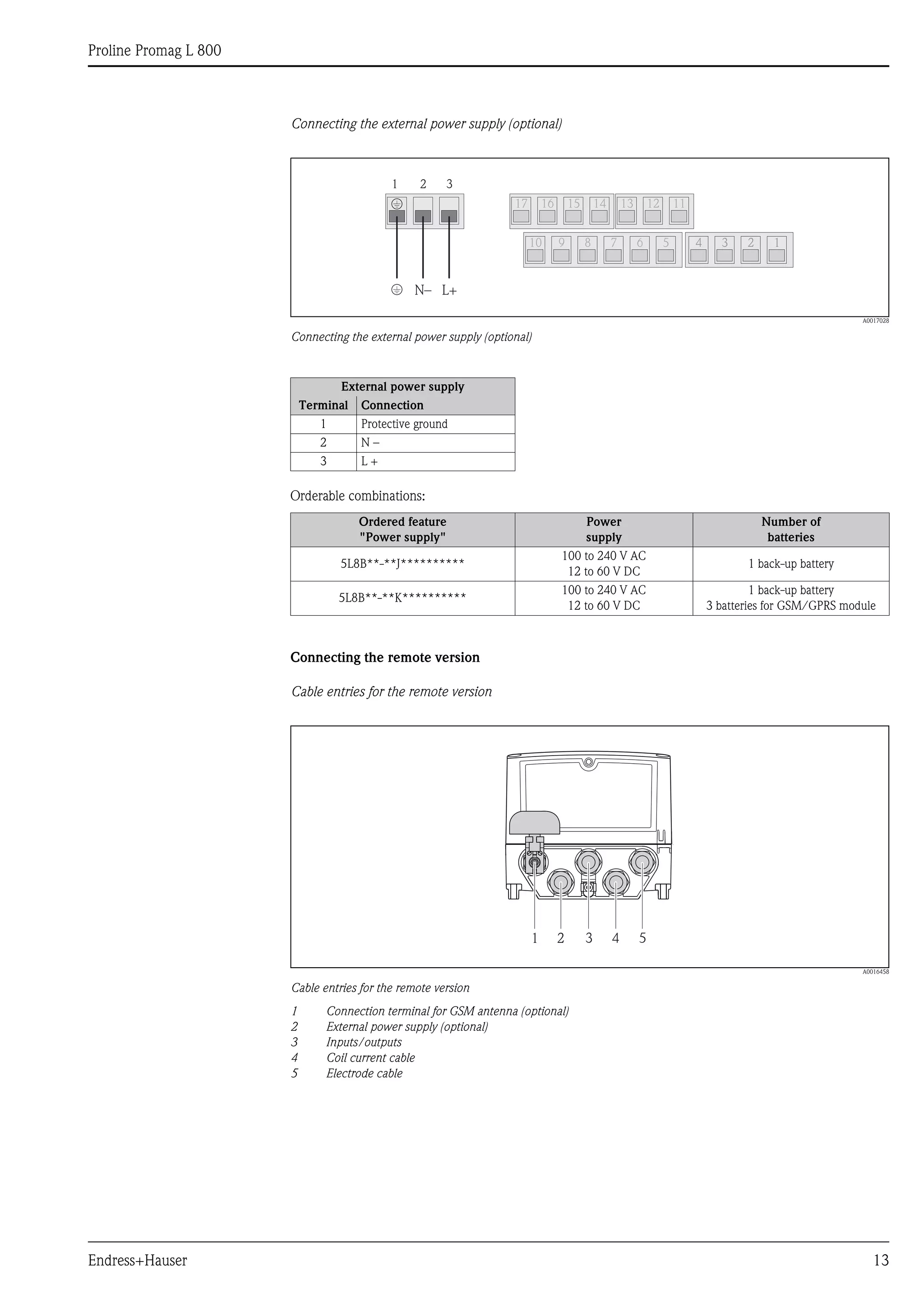
Performance characteristics
Reference operating
conditions
To DIN EN 29104
• Fluid temperature: (+28 ±2) °C / (+82 ± 4) °F
• Ambient temperature range: (+22 ±2) °C / (+72 ± 4) °F
• Warm-up period: 30 minutes
Installation conditions
• Inlet run > 10 × DN
• Outlet run > 5 × DN
• Sensor and transmitter grounded.
• The sensor is centered in the pipe.
The minimum conductivity information refers to measured value acquisition with the "CONT.PWR"
profile (continuous operation, the device records the maximum number of measured values, parameter
Prof., MPROF). Values can deviate if another profile is selected for measured value acquisition.
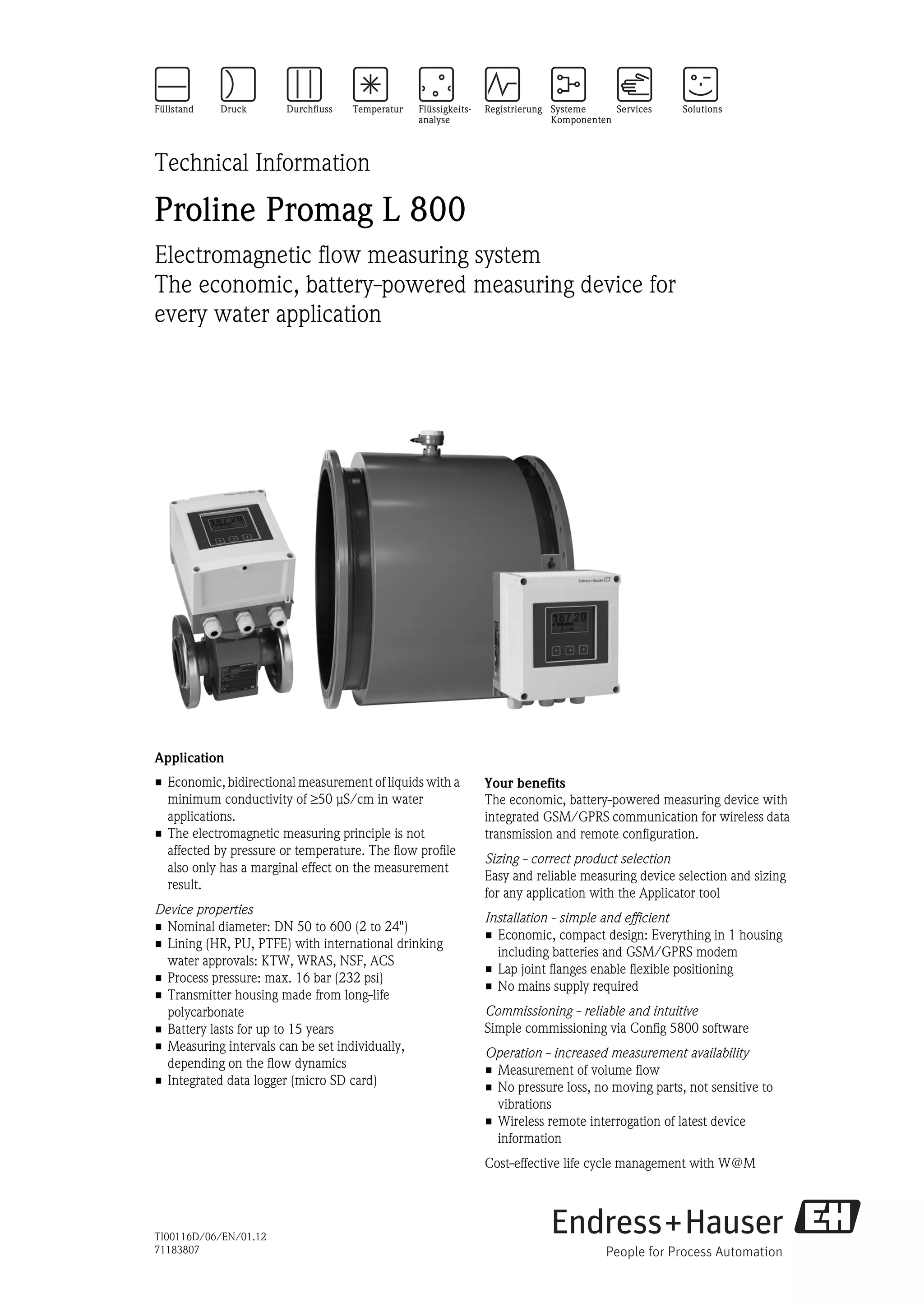
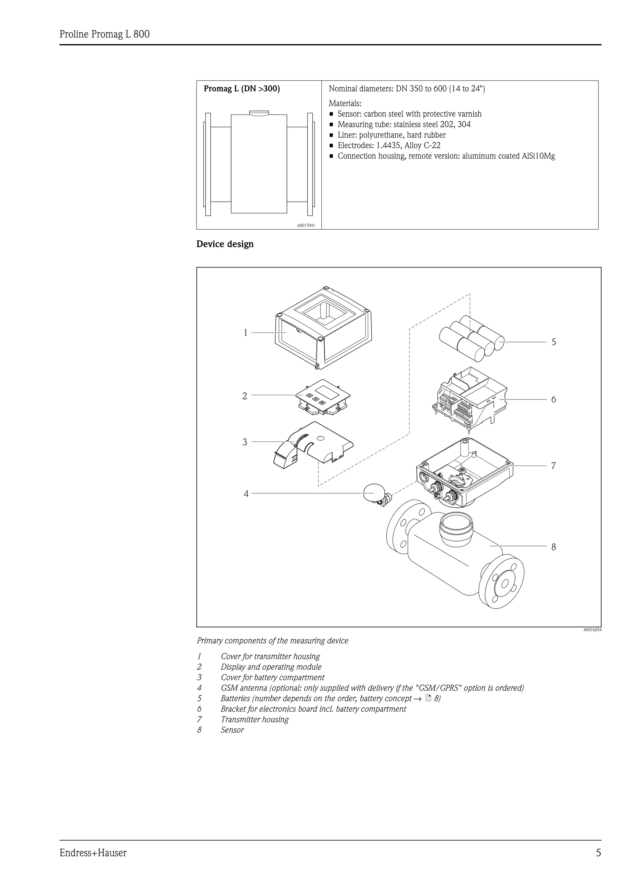
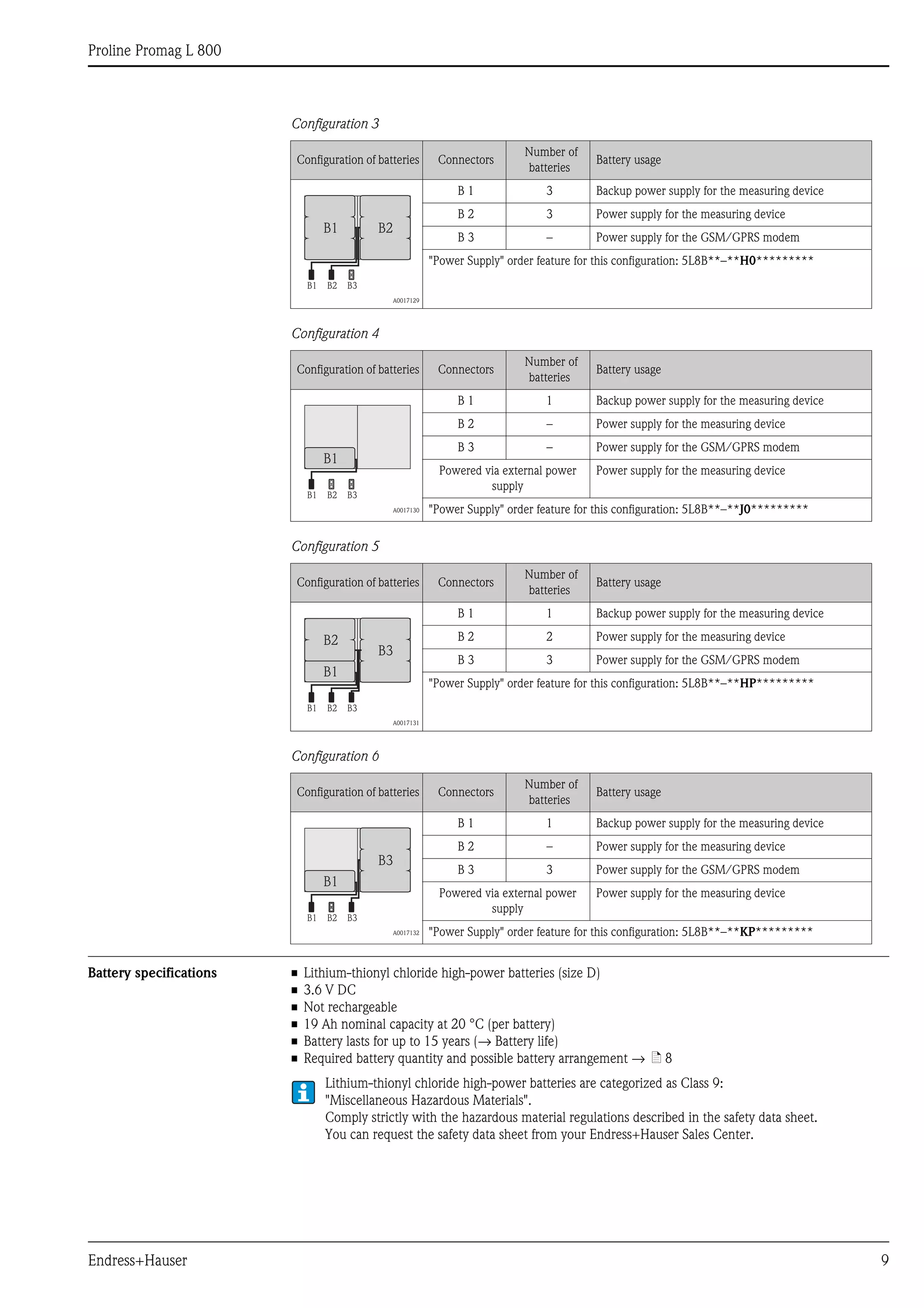
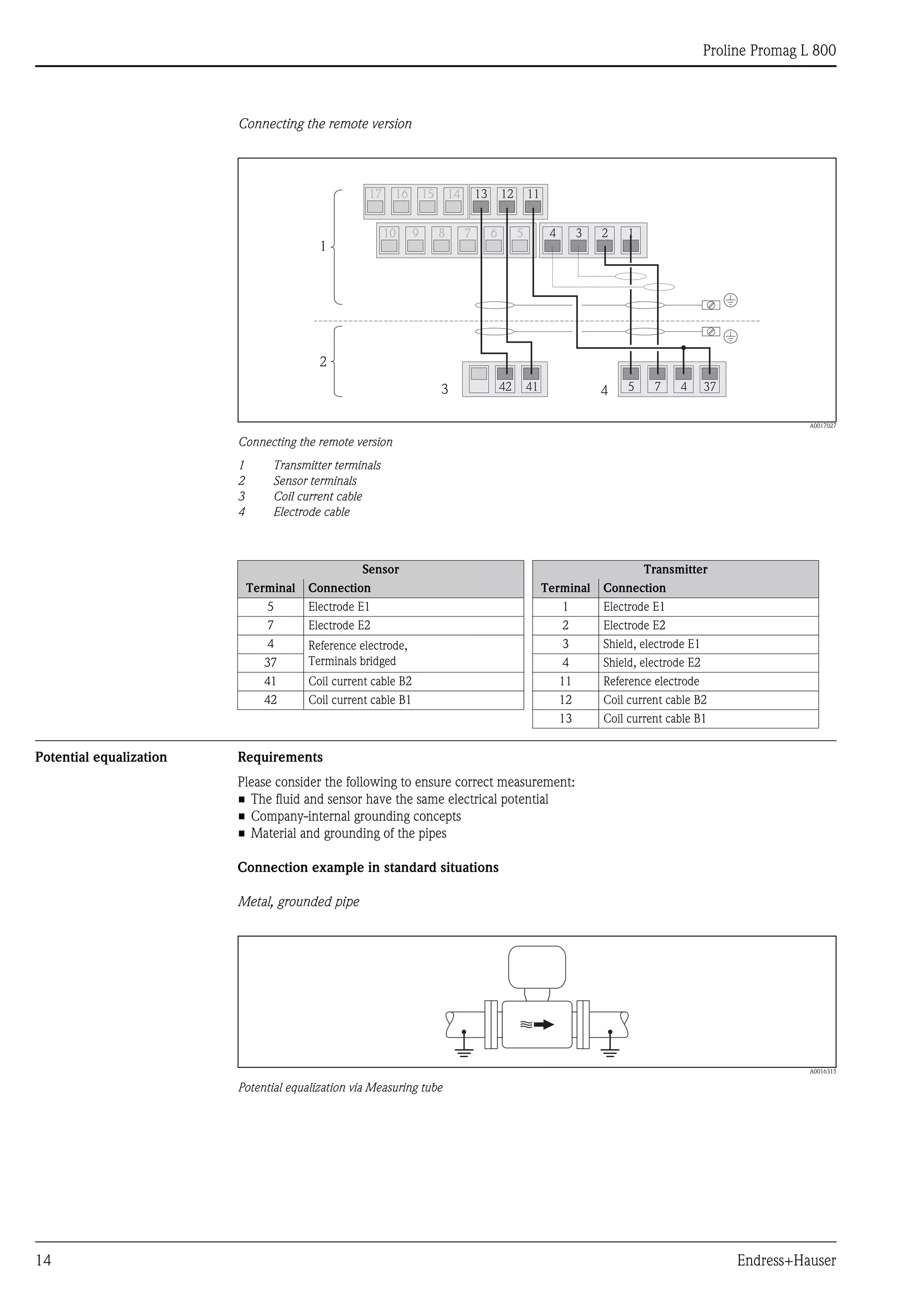
Maximum measured error Pulse output
±0.5% o.r. ± 2 mm/s (±0.5% o.r. ± 0.08 in/s)
o.r. = of reading
Fluctuations in the power supply do not have any effect within the specified range.
A0003200
Max. measured error in % of reading
Repeatability Max. ±0.2% o.r. ± 2.0 mm/s (±0.5% o.r. ± 0.08 in/s)
o.r. = of reading
2.5
[%]
2.0
1.5
1.0
0.5
0
0.5 %
0 1 2 4 6 8 10 [m/s]
v
5 10 15 20 25 30 32 [ft/s]0](https://image.slidesharecdn.com/prolinepromagl800-electromagneticflowmeter-130426215540-phpapp02/75/Proline-Promag-L-800-Electromagnetic-Flowmeter-18-2048.jpg)
![Proline Promag L 800
22 Endress+Hauser
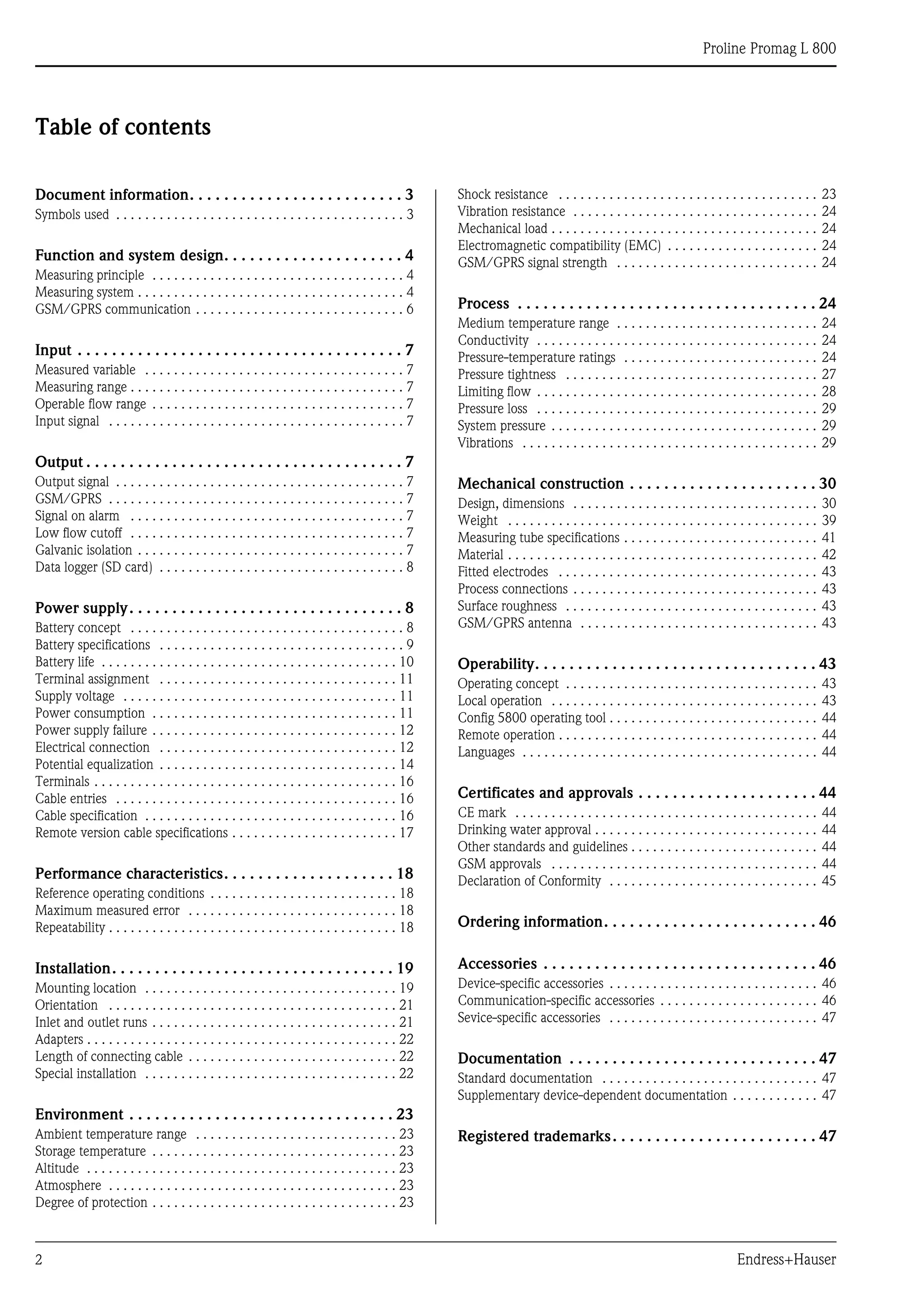
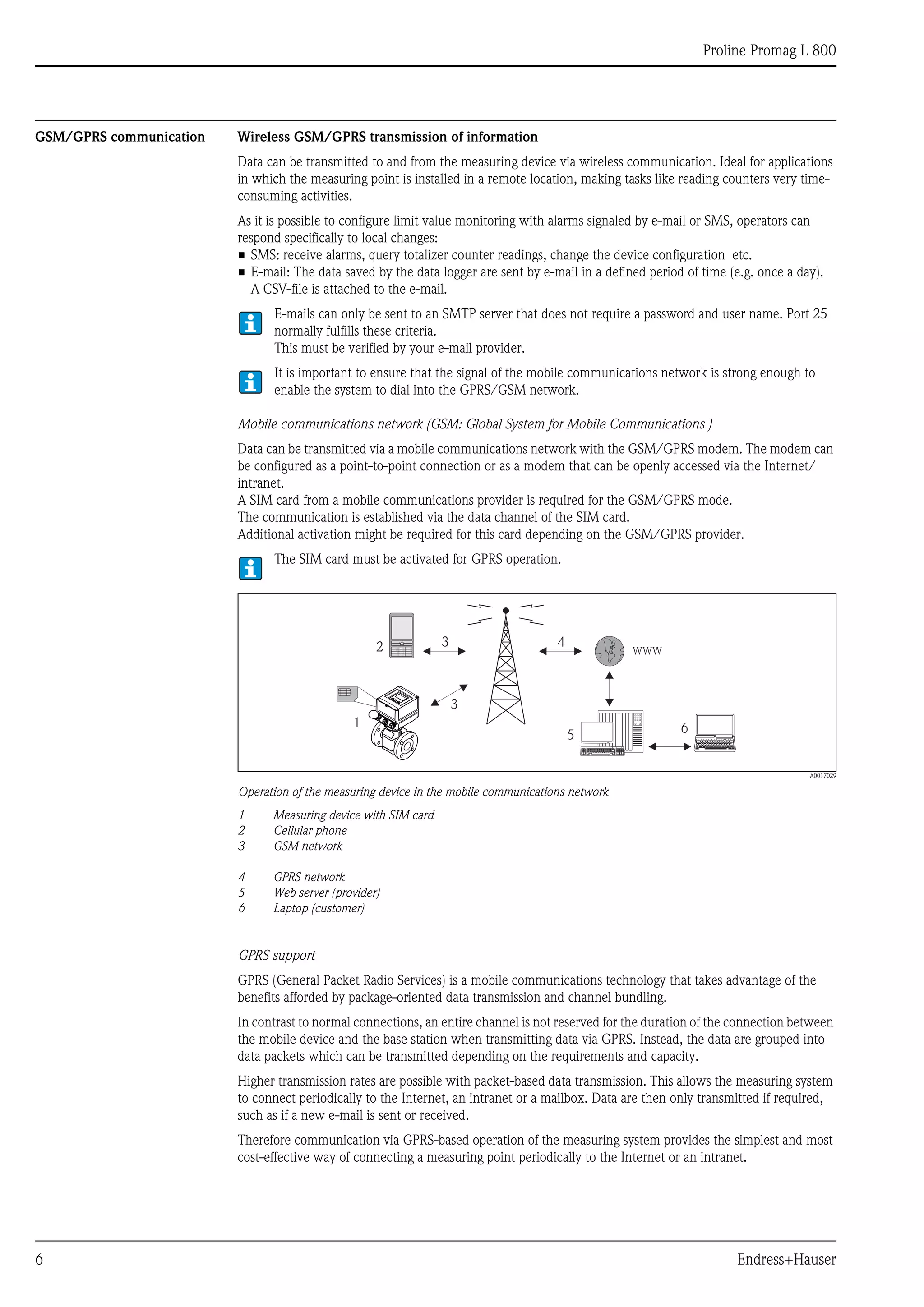
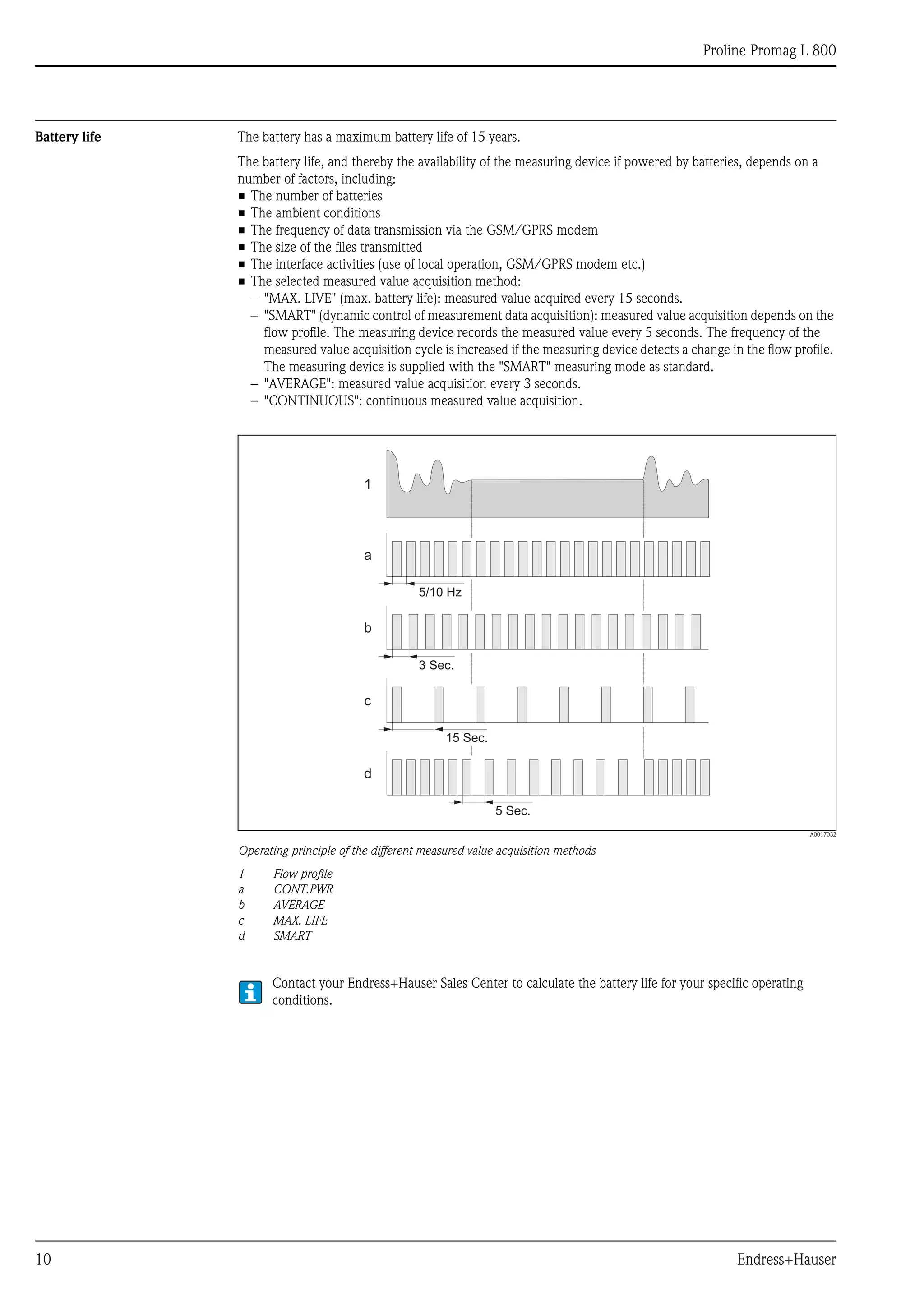
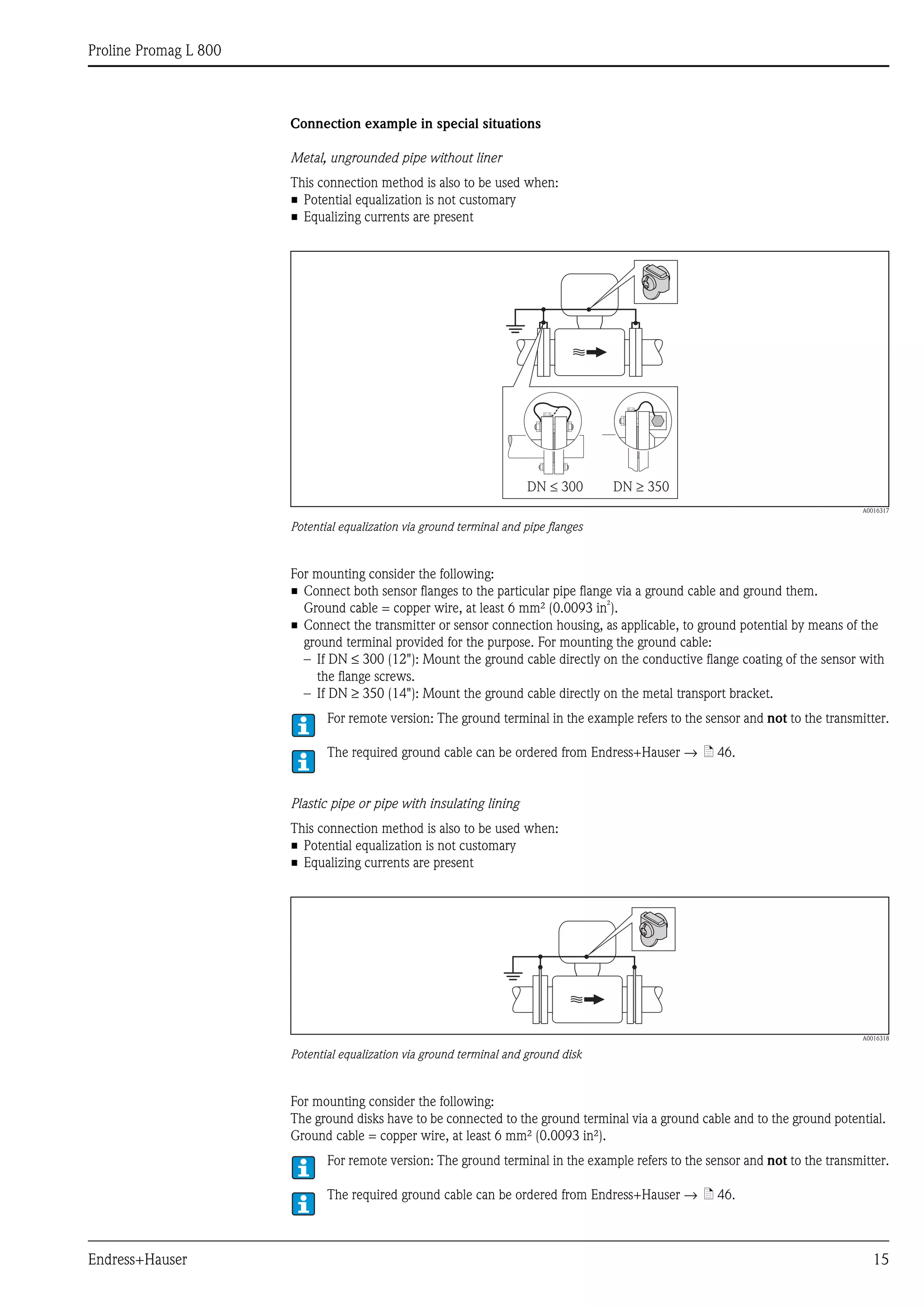
Adapters Suitable adapters to DIN EN 545 (double-flange reducers) can be used to install the sensor in larger-diameter
pipes.
The resultant increase in the rate of flow improves measuring accuracy with very slow-moving fluids. The
nomogram shown here can be used to calculate the pressure loss caused by reducers and expanders.
The nomogram only applies to liquids of viscosity similar to water.
Determining the pressure loss:
1. Calculate the ratio of the diameters d/D.
2. From the nomogram read off the pressure loss as a function of flow velocity (downstream from the
reduction) and the d/D ratio.
A0016359
Pressure loss due to adapters
Length of connecting cable The maximum connecting cable length is 20 m (35.6 ft).
When mounting the remote version, please note the following to achieve correct measuring results:
• Fix the cable run or route it in an armored conduit. Cable movements can falsify the measuring signal
especially in the case of low fluid conductivities.
• Route the cable well clear of electrical machines and switching elements.
• Ensure potential equalization between sensor and transmitter, if necessary.
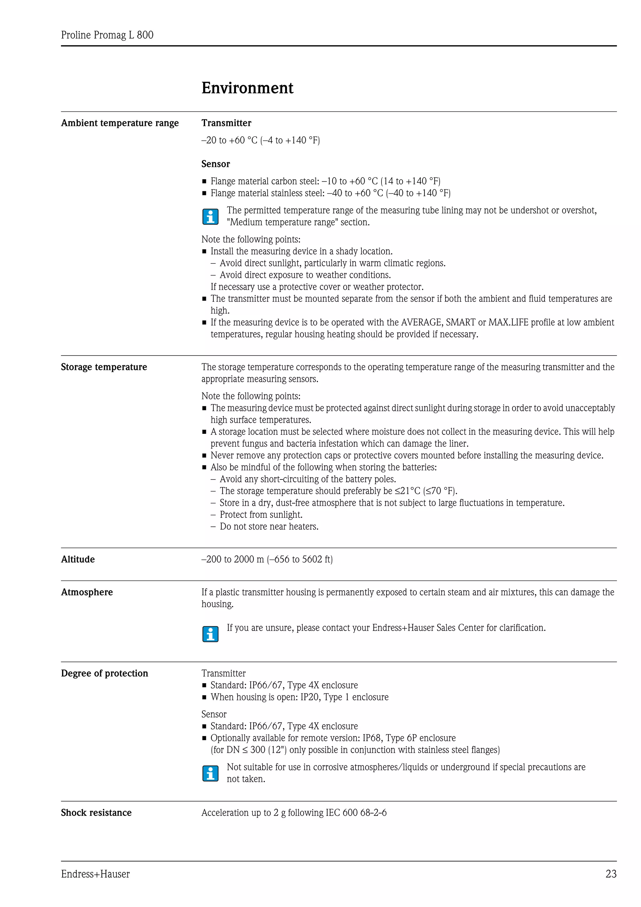
Special installation Weather protection cover
To ensure that the optional weather protection cover can be easily opened, maintain the following minimum
head clearance: 350 mm (200 in)
100
10
0.5d / D
[mbar]
0.6 0.7 0.8 0.9
1 m/s
2 m/s
3 m/s
4 m/s
5 m/s
6 m/s
7 m/s
8 m/s
1
Dd
max. 8°](https://image.slidesharecdn.com/prolinepromagl800-electromagneticflowmeter-130426215540-phpapp02/75/Proline-Promag-L-800-Electromagnetic-Flowmeter-22-2048.jpg)
![Proline Promag L 800
24 Endress+Hauser
Vibration resistance Acceleration up to 2 g following IEC 600 68-2-6
Mechanical load Transmitter housing
• The transmitter housing must be protected against mechanical effects, such as shock, impact etc.
It is sometimes preferable to use the remote device version.
• The transmitter housing must never be used as a ladder or climbing aid!
Electromagnetic compatibility
(EMC)
In accordance with IEC/EN 61326
GSM/GPRS signal strength It is important to ensure that the signal of the mobile communications network is strong enough to enable the
system to dial into the GPRS/GSM network.
Process
Medium temperature range Sensor
The permissible temperature depends on the lining of the measuring tube.
• 0 to +80 °C (+32 to +176 °F) for hard rubber, DN 350 to 600 (14 to 24")
• –20 to +50 °C (–4 to +122 °F) for polyurethane, DN 50 to 600 (2 to 24")
• –20 to +90 °C (–4 to +194 °F) for PTFE, DN 50 to 300 (2 to 12")
Conductivity The minimum conductivity is 50 μS/cm.
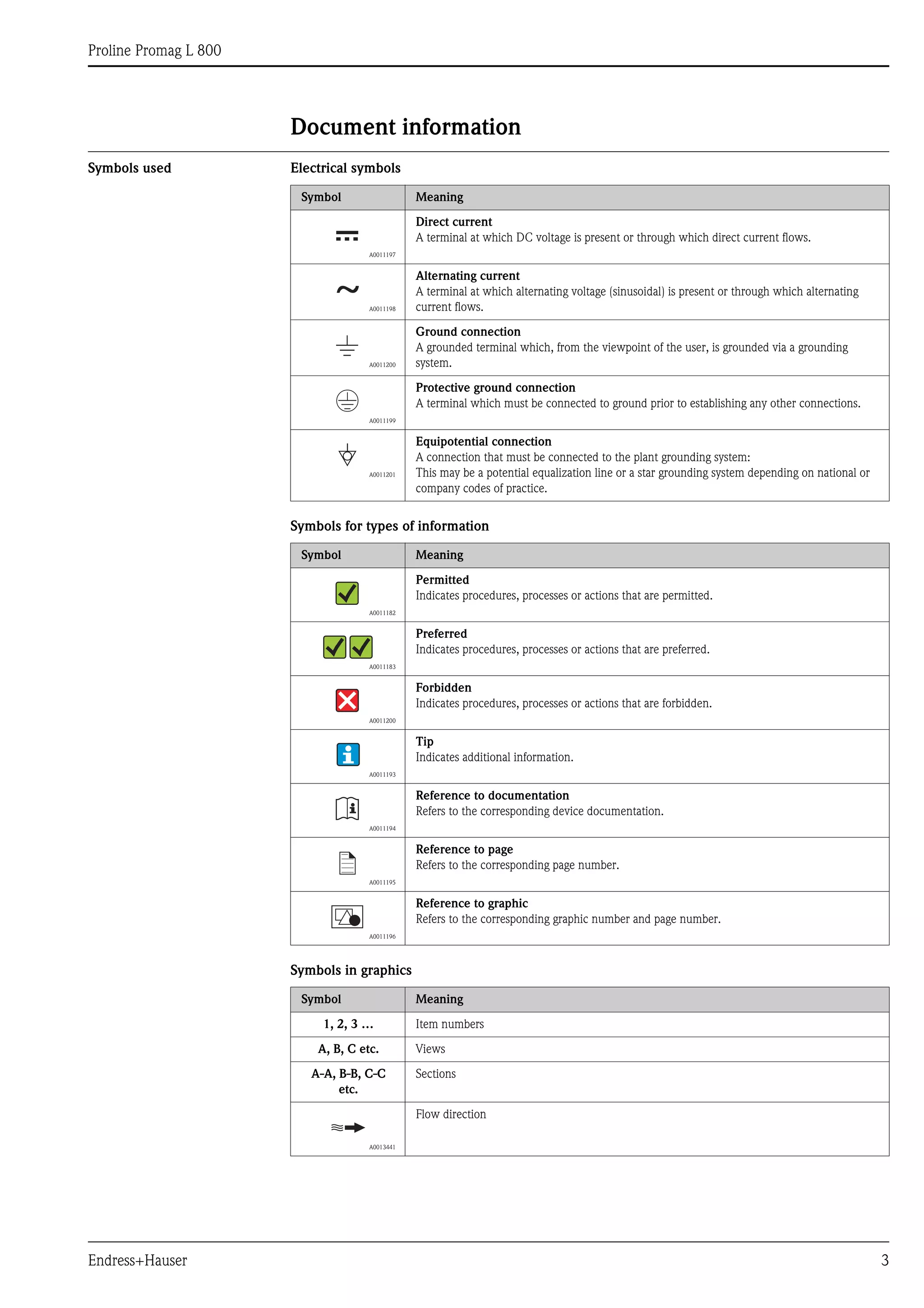
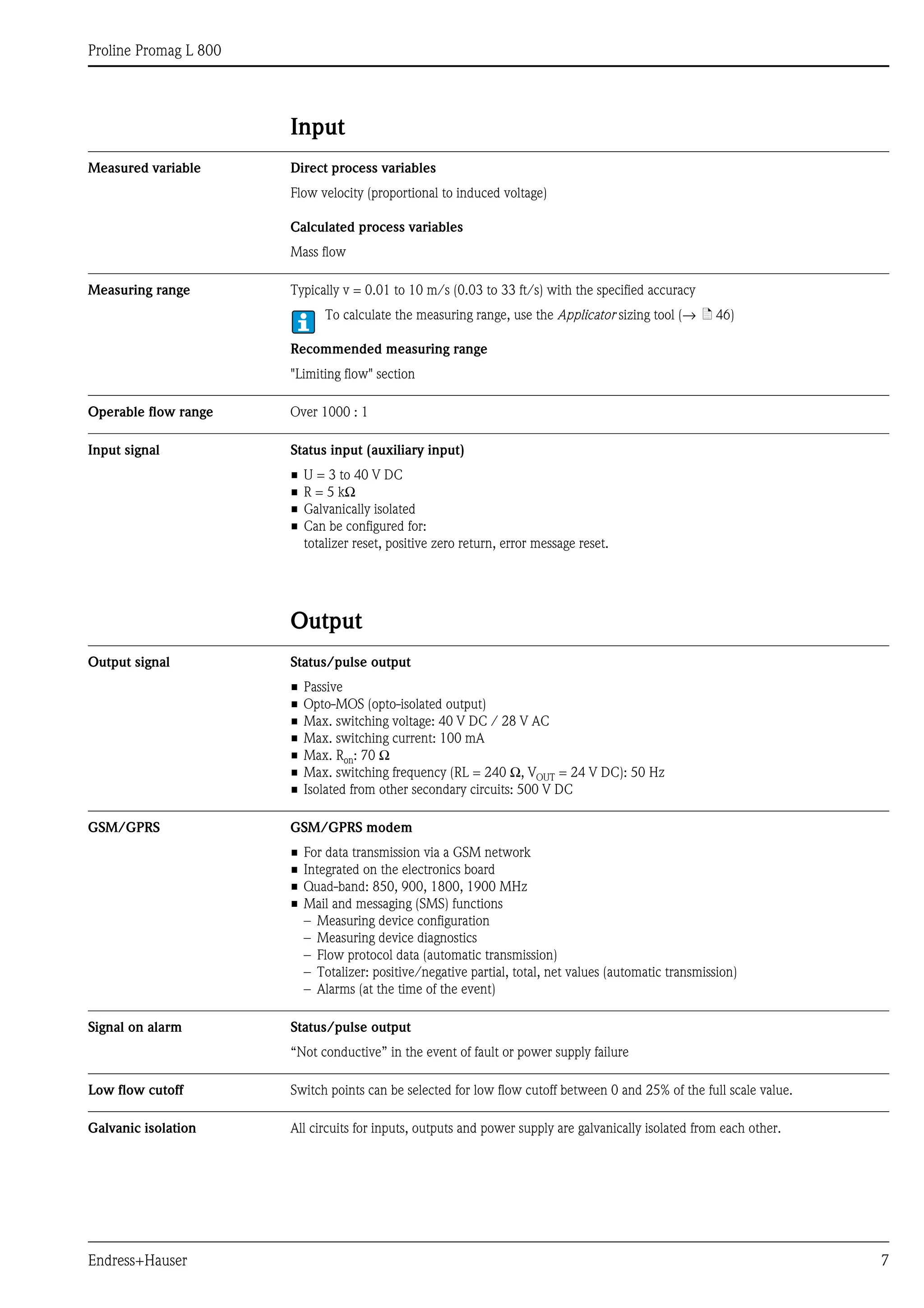
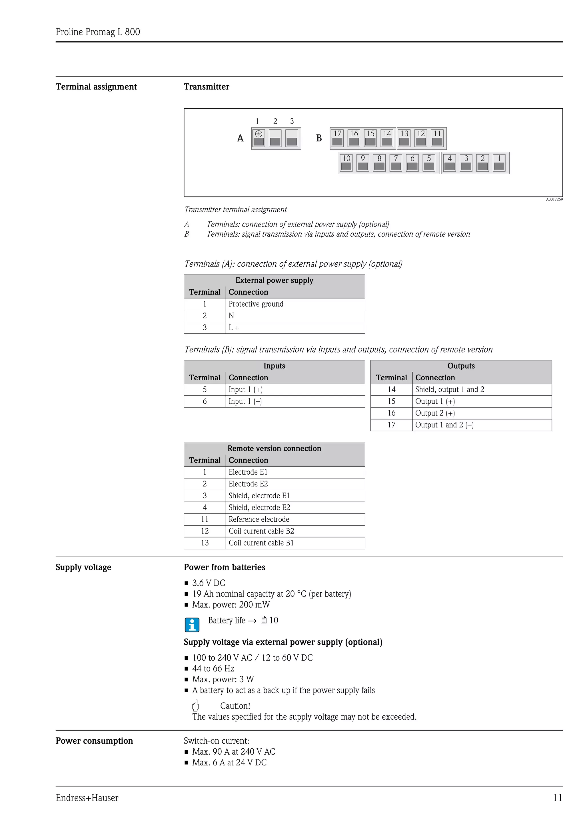
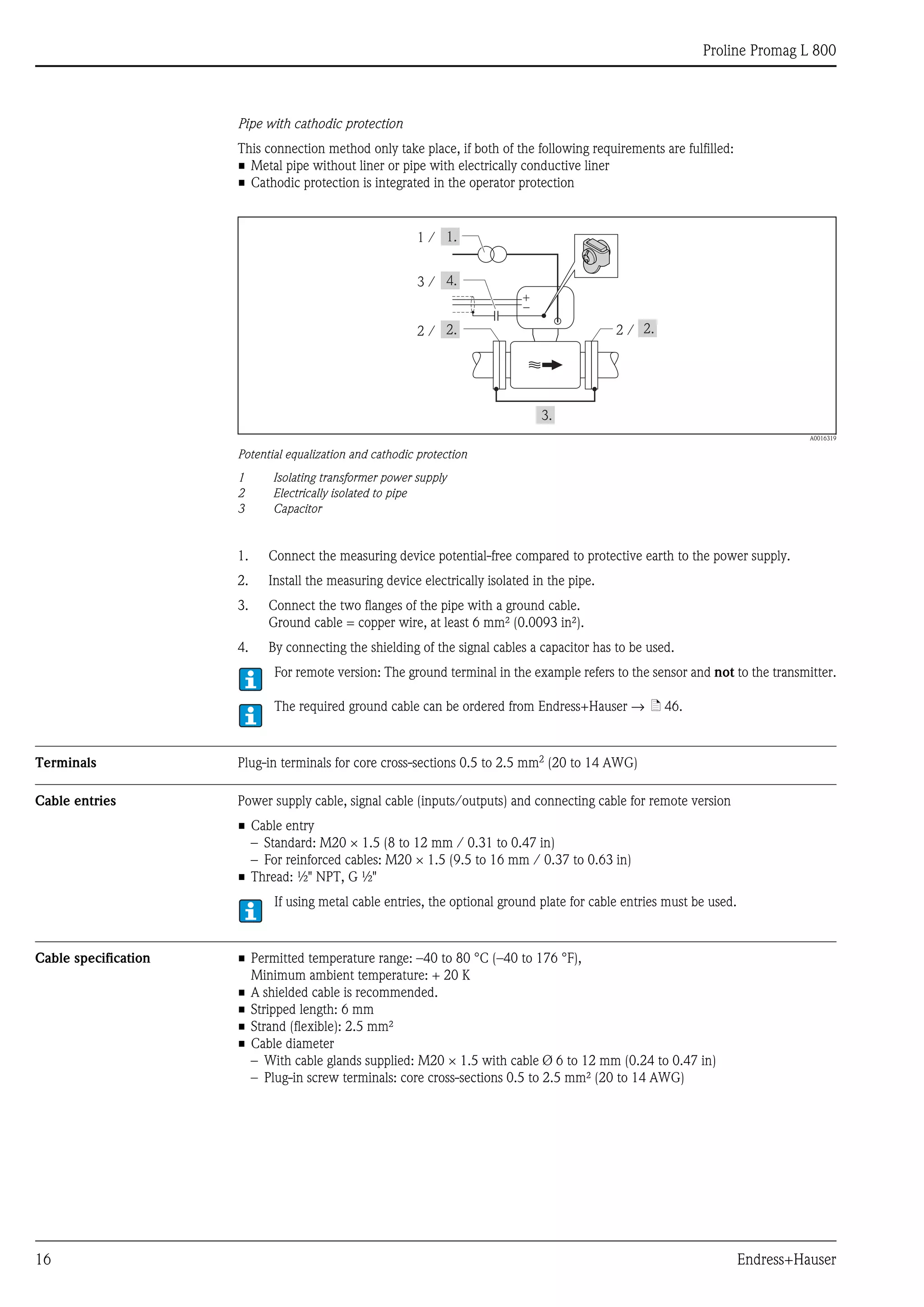
Pressure-temperature ratings The following material load diagrams refer to the entire device and not just the process connection.
Flange connection according to EN 1092-1 (DIN 2501)
A0011571
Lap joint flange PN 10/16, materials 1.4306/304L and 1.4307/304L, DN 50 to 300 (2 to 12")
PN16
0
5
10
15
20
[bar][psi]
-60 -40 -20 0 20 40 60 80 100 120 140 [°C]
[°F]0-40 100 200 300
200
100
300
0
PN10](https://image.slidesharecdn.com/prolinepromagl800-electromagneticflowmeter-130426215540-phpapp02/75/Proline-Promag-L-800-Electromagnetic-Flowmeter-24-2048.jpg)
![Proline Promag L 800
Endress+Hauser 25
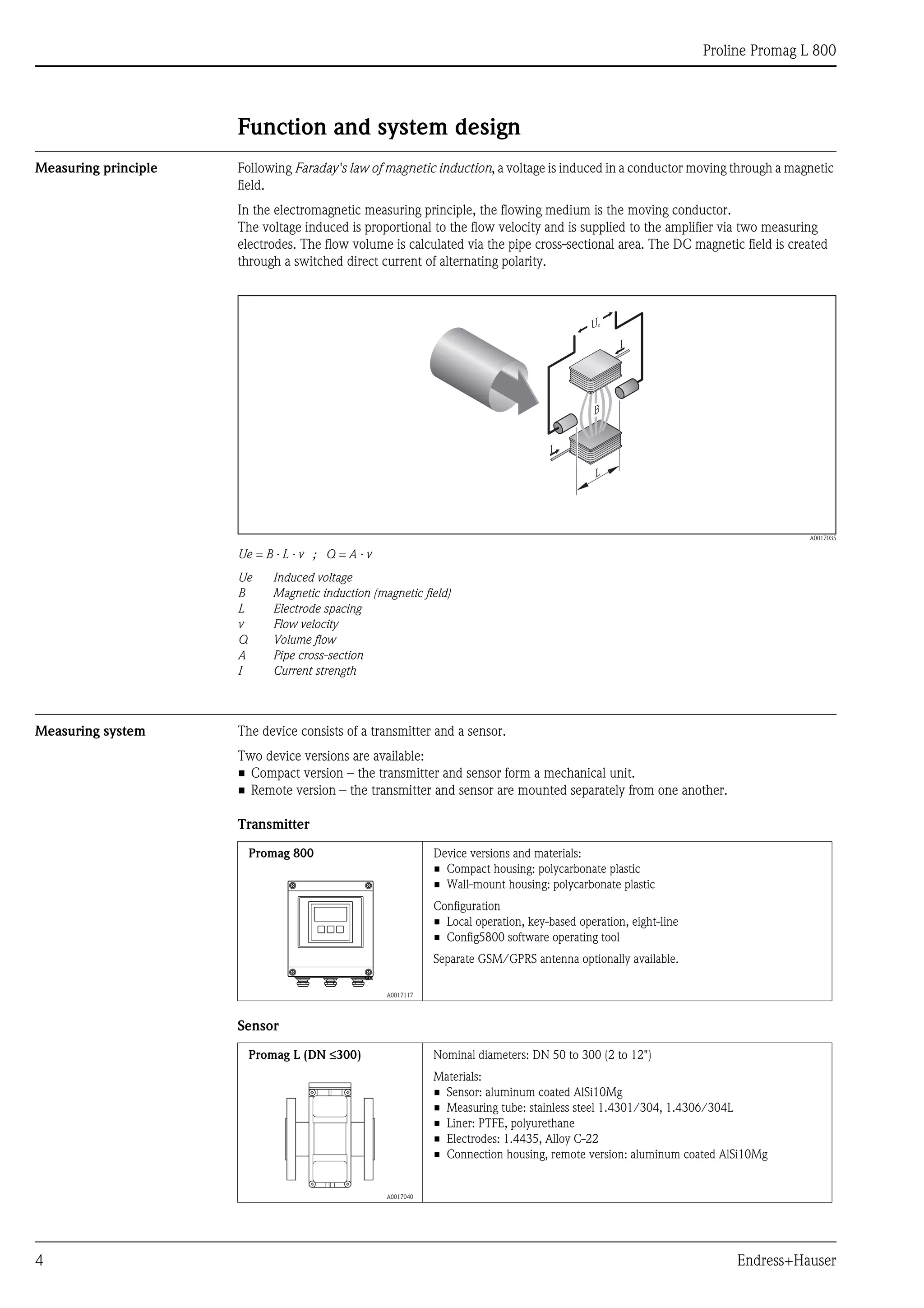
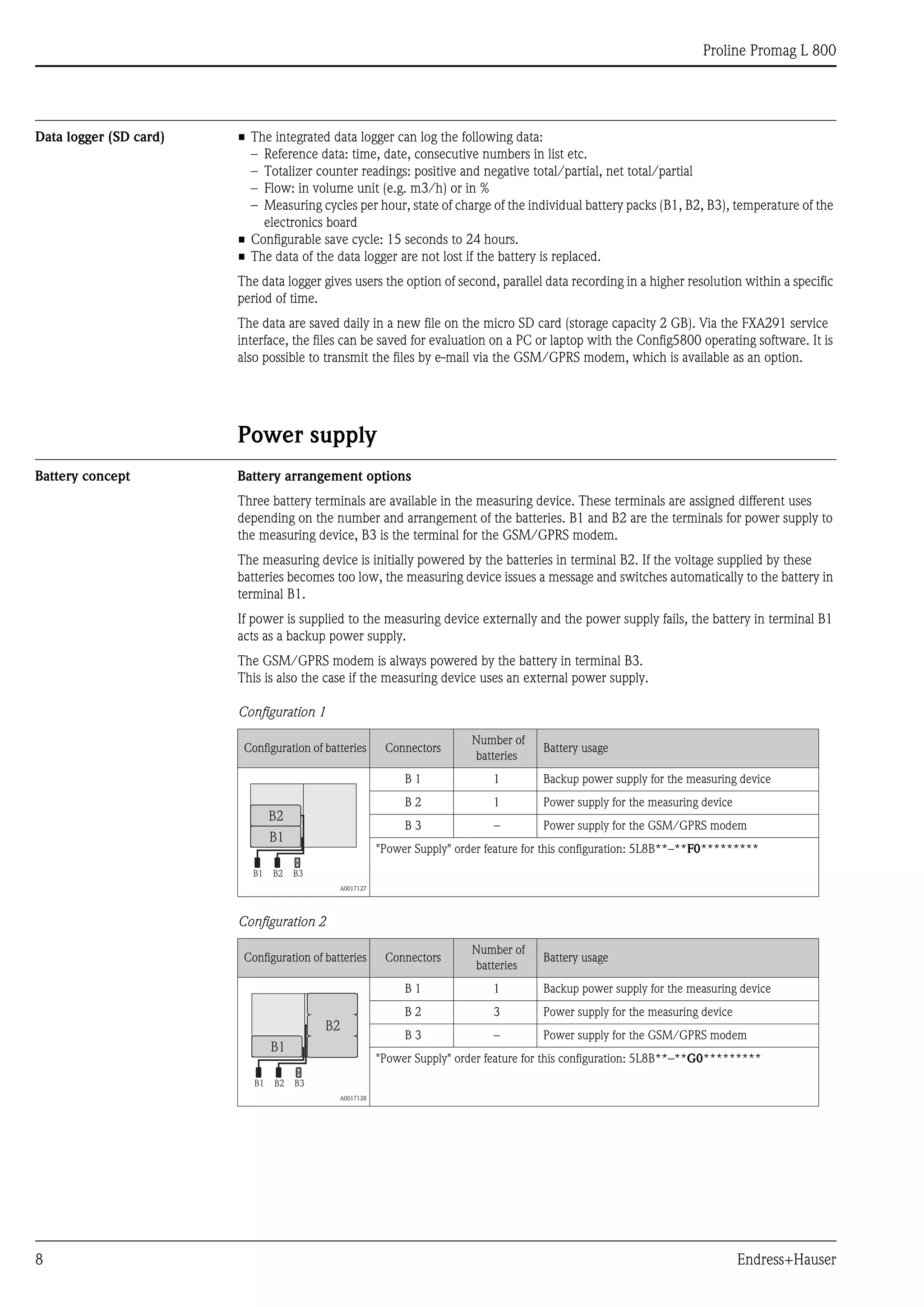
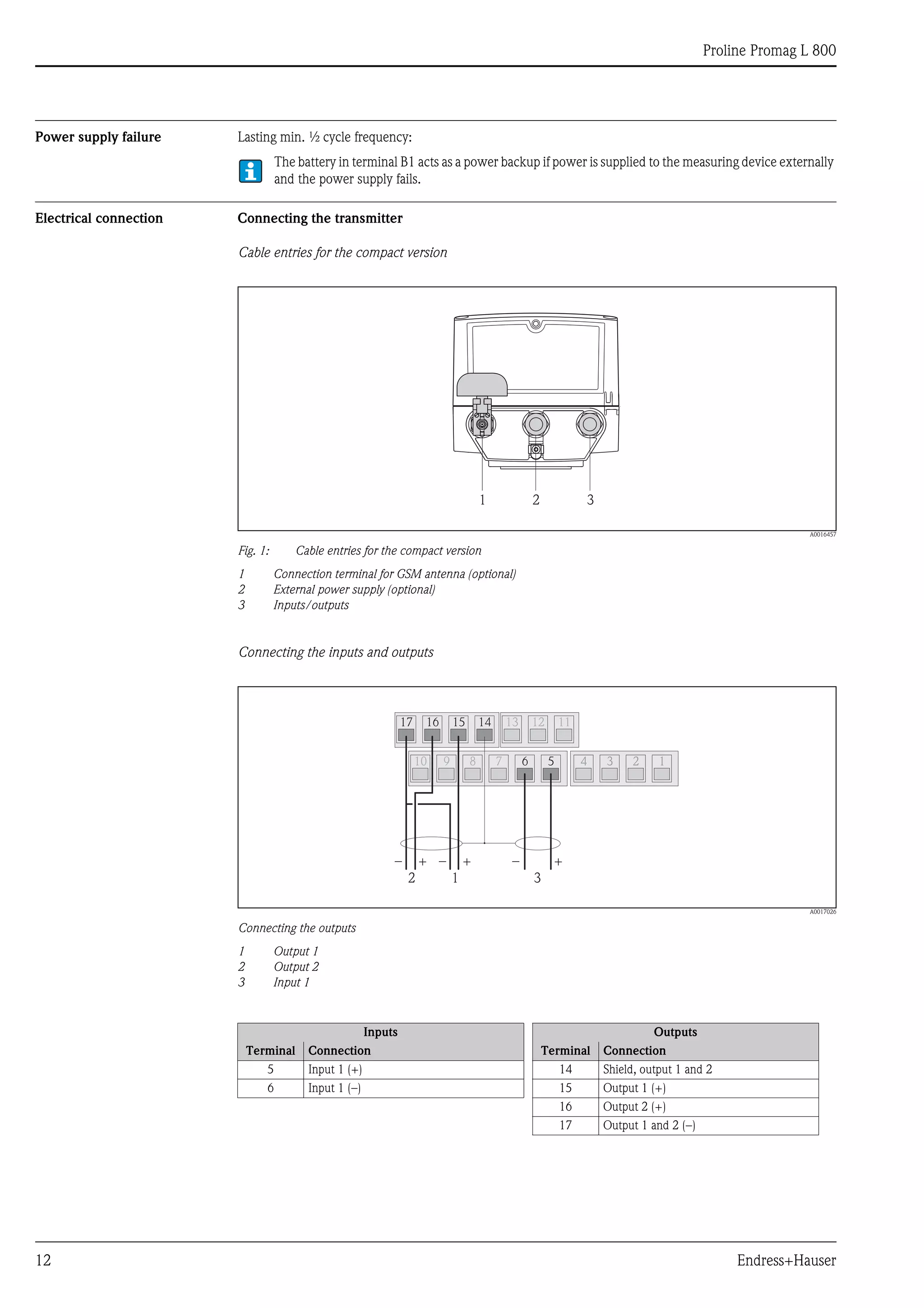
Flange connection according to EN 1092-1 (DIN 2501)
A0011573
Lap joint flange PN 10, material 1.4301/304, DN 50 to 300 (2 to 12")
Flange connection according to EN 1092-1 (DIN 2501)
A0011568
Fixed flange PN 6/10, materials 1.0038 (S235JRG2) and A105, DN 350 to 600 (14 to 24");
Lap joint flange PN 16, material 1.0038 (S235JRG2), DN 50 to 150 (2 to 6")
Flange connection according to ASME B16.5
A0011572
Lap joint flange Class 150, material A105, DN 50 to 300 (2 to 12")
PN10
0
5
10
15
20
[bar][psi]
-60 -40 -20 0 20 40 60 80 100 120 140 [°C]
[°F]0-40 100 200 300
200
100
300
0
PN16
0
5
10
15
20
[bar][psi]
-40 -20 0 20 40 60 80 100 120 140 [°C]
0-40 100 200 300
200
100
300
0
[°F]
PN10
PN6
-40 [°C]-20 0 20 40 60 80 100 120 140
0-40 100 200 300 [°F]
0
10
20
30
[bar][psi]
200
100
400
300
500
0
DN50…250(2"…10")
DN300(12")](https://image.slidesharecdn.com/prolinepromagl800-electromagneticflowmeter-130426215540-phpapp02/75/Proline-Promag-L-800-Electromagnetic-Flowmeter-25-2048.jpg)
![Proline Promag L 800
26 Endress+Hauser
Flange connection according to ASME B16.5
A0011580
Lap joint flange Class 150, material 316L, DN 50 to 300 (2 to 12")
Flange connection according to ASME B16.5
A0017264
Fixed flange Class 150, material A105, DN 350 to 600 (14 to 24")
Flange connection according to AS 2129 and AS 4087
A0017265
Fixed flange PN 16
Materials 1.0044 (S275JR), 1.0425/316L (P265GH) and A105
DN 350 to 600 (14 to 24")
Fixed flange Table E
Materials 1.0038 (S235JRG2), 1.0345 (P235GH), 1.0425/316L (P265GH), A105 and FE410 WB
DN 350 to 600 (14 to 24")
0
10
20
30
[bar][psi]
-40 -20 0 20 40 60 80 100 120 140 [°C]
[°F]0-40 100 200 300
200
100
400
300
0
DN50…250(2"…10")
DN300(12")
Class150
0
10
20
30
40
[bar][psi]
-40 -20 0 20 40 60 80 100 120 140 [°C]
[°F]0-40 100 200 300
200
100
400
300
500
0
-40 -20 0 20 40 60 80 100 120 140[°C]
0
10
5
20
15
[bar]
0-40 100 200 300
[psi]
200
100
300
0
TableE
PN16
[°F]](https://image.slidesharecdn.com/prolinepromagl800-electromagneticflowmeter-130426215540-phpapp02/75/Proline-Promag-L-800-Electromagnetic-Flowmeter-26-2048.jpg)
![Proline Promag L 800
Endress+Hauser 27
Pressure tightness Liner: polyurethane, hard rubber
Measuring tube lining: PTFE
Nominal diameter
Measuring
tube lining
Liner pressure tightness: limit values for
absolute pressure at different fluid temperatures
[mm] [in]
25 °C/77 °F 50 °C/122 °F 80° C/176 °F
[mbar]/[psi] [mbar]/[psi] [mbar]/[psi]
50…600 2…24" Polyurethane 0 0 -
350…600 14…24" Hard rubber 0 0 0
Nominal diameter
Measuring
tube lining
Liner pressure tightness: limit values for
absolute pressure at different fluid temperatures
[mm] [in]
25 °C/77 °F 90 °C/194 °F
[mbar] [psi] [mbar] [psi]
50 2" PTFE 0 0 0 0
65 - PTFE 0 0 40 0.58
80 3" PTFE 0 0 40 0.58
100 4" PTFE 0 0 135 1.96
125 - PTFE 135 1.96 240 3.48
150 6" PTFE 135 1.96 240 3.48
200 8" PTFE 200 2.90 290 4.21
250 10" PTFE 330 4.79 400 5.80
300 12" PTFE 400 5.80 500 7.25](https://image.slidesharecdn.com/prolinepromagl800-electromagneticflowmeter-130426215540-phpapp02/75/Proline-Promag-L-800-Electromagnetic-Flowmeter-27-2048.jpg)
![Proline Promag L 800
28 Endress+Hauser
Limiting flow The diameter of the pipe and the flow rate determine the nominal diameter of the sensor. The optimum velocity
of flow is between 2 and 3 m/s (6.56 to 9.84 ft/s). Also match the velocity of flow (v) to the physical properties
of the fluid:
• v < 2 m/s (v < 6.5 ft/s): for abrasive fluids (potter's clay, lime milk, ore slurry etc.)
• v > 2 m/s (v > 6.5 ft/s): for fluids producing buildup (wastewater sludge etc.)
Flow characteristic values in SI units
Flow characteristic values in US units
Nominal
diameter
Recommended
flow
min./max. full scale
value
Factory setting
Full scale value Pulse value
approx. 2 pulse/s for
Low flow cut off
[mm] (v ≈ 0.3 or 10 m/s) (v ≈ 2.5 m/s) (v ≈ 2.5 m/s) (v ≈ 0.04 m/s)
50 35…1100 dm³/min 300 dm3/min 0.10 dm3 10 dm3/min
65 60…2000 dm³/min 500 dm3/min 0.20 dm3 15 dm3/min
80 90…3000 dm³/min 750 dm3/min 0.30 dm3 20 dm3/min
100 145…4700 dm³/min 1200 dm3/min 0.50 dm3 40 dm3/min
125 220…7500 dm³/min 1850 dm3/min 0.75 dm3 60 dm3/min
150 20…600 m³/h 150 m3/h 0.001 m3 5 m3/h
200 35…1100 m³/h 300 m3/h 0.002 m3 10 m3/h
250 55…1700 m³/h 500 m3/h 0.003 m3 15 m3/h
300 80…2400 m³/h 750 m3/h 0.004 m3 20 m3/h
350 110…3300 m³/h 1000 m3/h 0.006 m3 25 m3/h
375 140…4200 m³/h 1200 m3/h 0.008 m3 35 m3/h
400 140…4200 m³/h 1200 m3/h 0.008 m3 35 m3/h
450 180…5400 m³/h 1500 m3/h 0.010 m3 40 m3/h
500 220…6600 m³/h 2000 m3/h 0.012 m3 50 m3/h
600 310…9600 m³/h 2500 m3/h 0.017 m3 80 m3/h
Nominal
diameter
Recommended
flow
min./max. full scale value
Factory setting
Full scale value Pulse value
approx. 2 pulse/s for
Low flow cut off
[in] (v ≈ 0.3 or 10 m/s) (v ≈ 2.5 m/s) (v ≈ 2.5 m/s) (v ≈ 0.04 m/s)
2" 10…300 gal/min 80 gal/min 0.03 gal 2.50 gal/min
2 ½" 16…500 gal/min 150 gal/min 0.05 gal 4.00 gal/min
3" 24…800 gal/min 200 gal/min 0.08 gal 6.00 gal/min
4" 40…1250 gal/min 300 gal/min 0.15 gal 10.0 gal/min
5" 60…1950 gal/min 500 gal/min 0.20 gal 15.0 gal/min
6" 90…2650 gal/min 700 gal/min 0.30 gal 20.0 gal/min
8" 155…4850 gal/min 1200 gal/min 0.50 gal 40.0 gal/min
10" 250…7500 gal/min 2000 gal/min 0.80 gal 60.0 gal/min
12" 350…10600 gal/min 3000 gal/min 1.15 gal 80.0 gal/min
14" 500…15000 gal/min 4000 gal/min 1.50 gal 115.0 gal/min
15" 600…19000 gal/min 5000 gal/min 2.00 gal 150.0 gal/min
16" 600…19000 gal/min 5000 gal/min 2.00 gal 150.0 gal/min
18" 800…24000 gal/min 6500 gal/min 2.50 gal 200.0 gal/min
20" 1000…30000 gal/min 7500 gal/min 3.00 gal 250.0 gal/min
24" 1400…44000 gal/min 12000 gal/min 5.00 gal 350.0 gal/min](https://image.slidesharecdn.com/prolinepromagl800-electromagneticflowmeter-130426215540-phpapp02/75/Proline-Promag-L-800-Electromagnetic-Flowmeter-28-2048.jpg)
![Proline Promag L 800
30 Endress+Hauser
Mechanical construction
Design, dimensions Compact version DN 50 to 300 (2 to 12")
A0017392
Dimensions in SI units
Dimensions in US units
DN L1)
A B C D E F G H J K
[mm] [mm] [mm] [mm] [mm] [mm] [mm] [mm] [mm] [mm] [mm] [mm]
50 200 216 189 120 165 157 269 353 84 94 182
65 200 216 189 180 165 157 294 403 109 94 182
80 200 216 189 180 165 157 294 403 109 94 182
100 250 216 189 180 165 157 294 403 109 94 182
125 250 216 189 260 165 157 334 484 150 140 182
150 300 216 189 260 165 157 334 484 150 140 182
200 350 216 189 324 165 157 359 539 180 156 182
250 450 216 189 400 165 157 384 589 205 156 182
300 500 216 189 460 165 157 409 639 230 166 182
1)
The length is independent of the selected pressure rating. Length in accordance with DVGW/ISO.
DN L1)
A B C D E F G H J K
[in] [in] [in] [in] [in] [in] [in] [in] [in] [in] [in] [in]
2" 7.87 8.50 7.44 4.72 6.50 6.18 10.59 13.90 3.32 3.70 7.17
3" 7.87 8.50 7.44 7.10 6.50 6.18 11.57 15.87 4.30 3.70 7.17
4" 9.84 8.50 7.44 7.10 6.50 6.18 11.57 15.87 4.30 3.70 7.17
6" 11.8 8.50 7.44 10.2 6.50 6.18 13.15 19.06 5.91 5.51 7.17
8" 13.8 8.50 7.44 12.8 6.50 6.18 14.13 21.22 7.10 6.14 7.17
10" 17.7 8.50 7.44 15.8 6.50 6.18 15.12 23.19 8.08 6.14 7.17
12" 19.7 8.50 7.44 18.1 6.50 6.18 16.10 25.16 9.06 6.54 7.17
1)
The length is independent of the selected pressure rating. Length in accordance with DVGW/ISO.
A
C
B
L
H
J
F
G
E
D
K](https://image.slidesharecdn.com/prolinepromagl800-electromagneticflowmeter-130426215540-phpapp02/75/Proline-Promag-L-800-Electromagnetic-Flowmeter-30-2048.jpg)
![Proline Promag L 800
Endress+Hauser 31
Compact version DN 350 to 600 (14 to 24")
A0017395
Dimensions in SI units
DN L A B C D E F G H J K
[mm] [mm] [mm] [mm] [mm] [mm] [mm] [mm] [mm] [mm] [mm] [mm]
350 550 216 189
Dependingonthepressurerating:
seethefollowingtable
165 157 433
Dependingonthepressurerating:
seethefollowingtable
Dependingonthepressurerating:
seethefollowingtable
290 192
375 600 216 189 165 157 459 290 192
400 600 216 189 165 157 459 290 192
450 600 216 189 165 157 487 290 192
500 600 216 189 165 157 512 290 192
600 600 216 189 165 157 553 290 192
DN C G H
for pressure ratings for pressure ratings for pressure ratings
PN 6 PN 10 ASME AS PN 6 PN 10 ASME AS PN 6 PN 10 ASME AS
[mm] [mm] [mm] [mm] [mm] [mm] [mm] [mm] [mm] [mm] [mm] [mm] [mm]
350 490 505 533 525 678 685 700 695 245 252 267 262
375 – – – 550 – – – 734 – – – 275
400 540 565 597 580 729 741 757 749 270 282 298 290
450 595 615 635 640 784 794 804 807 297 307 317 320
500 645 670 699 705 834 847 861 864 322 335 349 352
600 755 780 813 825 930 943 959 965 377 390 406 412
LC
E
F
J
G
A
B
D
K](https://image.slidesharecdn.com/prolinepromagl800-electromagneticflowmeter-130426215540-phpapp02/75/Proline-Promag-L-800-Electromagnetic-Flowmeter-31-2048.jpg)
![Proline Promag L 800
32 Endress+Hauser
Dimensions in US units
DN L A B C D E F G H J K
[in] [in] [in] [in] [in] [in] [in] [in] [in] [in] [in] [in]
14" 21.6 8.50 7.44
Dependingonthepressurerating:
seethefollowingtable
6.50 6.18 17.05
Dependingonthepressurerating:
seethefollowingtable
Dependingonthepressurerating:
seethefollowingtable
11.42 7.56
15" 23.6 8.50 7.44 6.50 6.18 18.07 11.42 7.56
16" 23.6 8.50 7.44 6.50 6.18 18.07 11.42 7.56
18" 23.6 8.50 7.44 6.50 6.18 19.17 11.42 7.56
20" 23.6 8.50 7.44 6.50 6.18 20.16 11.42 7.56
24" 23.6 8.50 7.44 6.50 6.18 21.77 11.42 7.56
DN C G H
for pressure ratings for pressure ratings for pressure ratings
PN 6 PN 10 ASME AS PN 6 PN 10 ASME AS PN 6 PN 10 ASME AS
[in] [in] [in] [in] [in] [in] [in] [in] [in] [in] [in] [in] [in]
14" 19.29 19.88 20.98 20.67 26.69 26.97 27.56 27.36 9.65 9.92 10.51 10.31
15" – – – 21.67 – – – 28.90 – – – 10.83
16" 21.26 25.83 22.80 22.83 28.70 29.17 29.80 29.49 10.36 11.10 11.73 11.42
18" 23.43 24.21 25.00 25.20 30.87 31.26 31.65 31.77 11.69 12.09 12.48 12.60
20" 25.39 26.38 27.52 27.76 32.83 33.35 33.90 34.02 12.68 13.19 13.74 13.86
24" 29.72 30.71 32.01 32.48 36.61 37.13 37.76 37.99 14.84 15.35 15.98 16.22](https://image.slidesharecdn.com/prolinepromagl800-electromagneticflowmeter-130426215540-phpapp02/75/Proline-Promag-L-800-Electromagnetic-Flowmeter-32-2048.jpg)
![Proline Promag L 800
Endress+Hauser 33
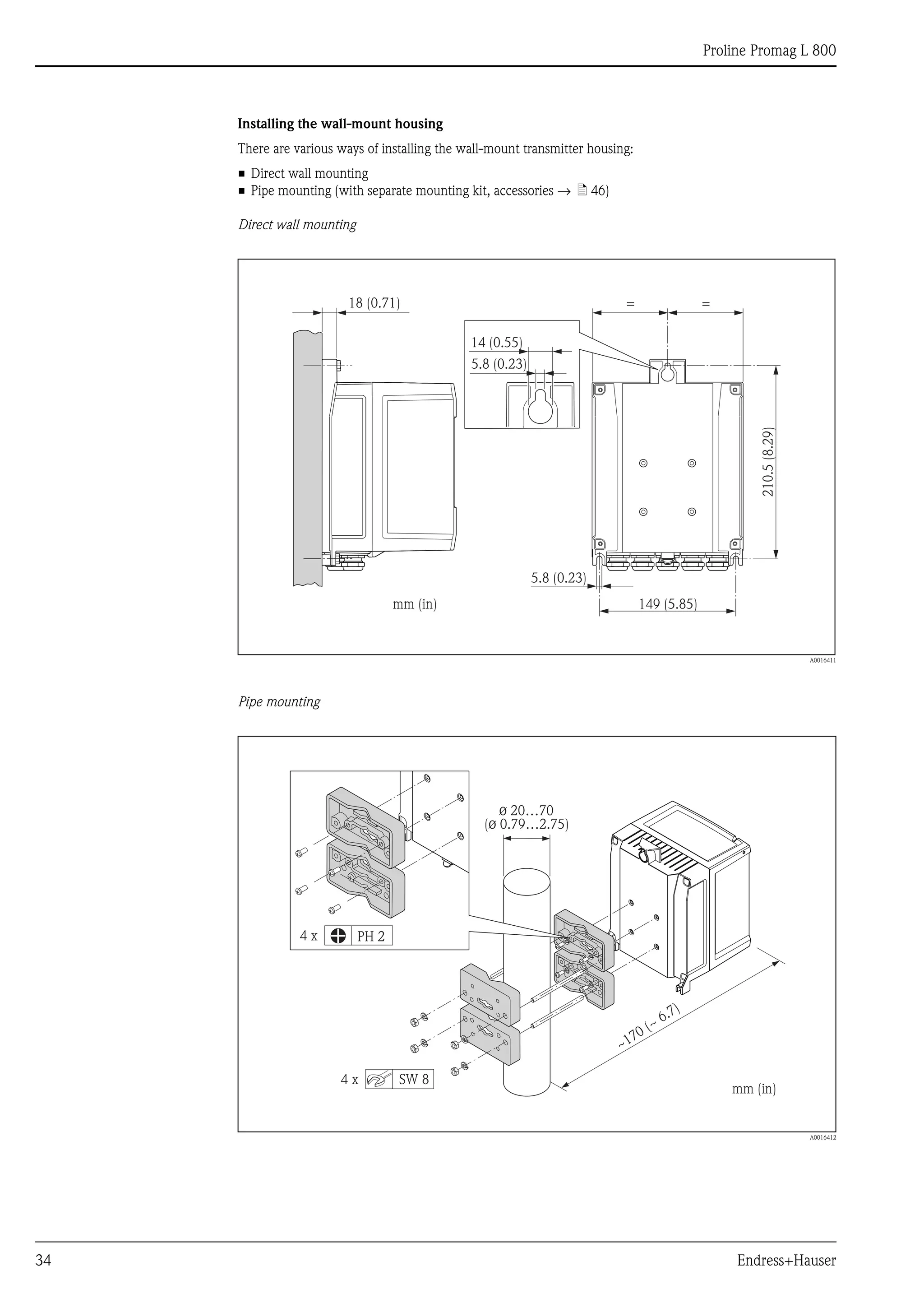
Transmitter remote version, wall-mount housing
"Housing" order feature, option N: remote, polycarbonate
A0017347
Dimensions in SI units
Dimensions in US units
A B C D E F G H J K L
[mm] [mm] [mm] [mm] [mm] [mm] [mm] [mm] [mm] [mm] [mm]
165 185 15 25 225 151.5 50 53 56 88.5 53
A B C D E F G H J K L
[in] [in] [in] [in] [in] [in] [in] [in] [in] [in] [in]
6.50 7.28 0.59 0.98 8.86 5.96 1.97 2.09 2.20 3.48 2.09
B
A
K
G
H
L
JJ
CD
E
F](https://image.slidesharecdn.com/prolinepromagl800-electromagneticflowmeter-130426215540-phpapp02/75/Proline-Promag-L-800-Electromagnetic-Flowmeter-33-2048.jpg)
![Proline Promag L 800
Endress+Hauser 35
Sensor remote version, DN 50 to 300 (2 to 12")
A0012462
Dimensions in SI units
Dimensions in US units
DN L1)
A B C D E F G H J
[mm] [mm] [mm] [mm] [mm] [mm] [mm] [mm] [mm] [mm] [mm]
50 200
129 163 143 102
286 202 84 120 94
65 200 336 227 109 180 94
80 200 336 227 109 180 94
100 250 336 227 109 180 94
125 250 417 267 150 260 140
150 300 417 267 150 260 140
200 350 472 292 180 324 156
250 450 522 317 205 400 156
300 500 572 342 230 460 166
1)
The length is independent of the selected pressure rating. Length in accordance with DVGW/ISO.
DN L1) A B C D E F G H J
[in] [in] [in] [in] [in] [in] [in] [in] [in] [in] [in]
2" 7.87
5.08 6.42 5.63 4.02
11.3 7.95 3.32 4.72 3.70
3" 7.87 13.2 8.94 4.30 7.10 3.70
4" 9.84 13.2 8.94 4.30 7.10 3.70
6" 11.8 16.4 10.5 5.91 10.2 5.51
8" 13.8 18.6 11.5 7.10 12.8 6.14
10" 17.7 20.6 12.5 8.08 15.8 6.14
12" 19.7 22.5 13.5 9.06 18.1 6.54
1) The length is independent of the selected pressure rating. Length in accordance with DVGW/ISO.
J
L
E
GF
H
B
C
A
D](https://image.slidesharecdn.com/prolinepromagl800-electromagneticflowmeter-130426215540-phpapp02/75/Proline-Promag-L-800-Electromagnetic-Flowmeter-35-2048.jpg)
![Proline Promag L 800
36 Endress+Hauser
Sensor remote version DN 350 to 600 (14 to 24")
A0014987
Dimensions in SI units
DN L A B C D E F G H
[mm] [mm] [mm] [mm] [mm] [mm] [mm] [mm] [mm] [mm]
350 550 129 163 102 –
Dependingonthepressurerating:
seethefollowingtable
353 290
Dependingonthepressurerating:
seethefollowingtable
375 600 – 379
400 600 – 379
450 600 – 407
500 600 – 432
600 600 – 473
DN E H
for pressure ratings for pressure ratings
PN 6 PN 10 ASME AS PN 6 PN 10 ASME AS
[mm] [mm] [mm] [mm] [mm] [mm] [mm] [mm] [mm]
350 598 605 620 615 490 505 533 525
375 – – – 654 – – – 550
400 649 661 677 669 540 565 597 580
450 704 714 724 727 595 615 635 640
500 754 767 781 784 645 670 699 705
600 850 863 879 885 755 780 813 825
L
G
E
F
H
A B
C](https://image.slidesharecdn.com/prolinepromagl800-electromagneticflowmeter-130426215540-phpapp02/75/Proline-Promag-L-800-Electromagnetic-Flowmeter-36-2048.jpg)
![Proline Promag L 800
Endress+Hauser 37
Dimensions in US units
DN L A B C D E F G H
[mm] [mm] [mm] [mm] [mm] [mm] [mm] [mm] [mm] [mm]
14" 21.6 5.08 6.42 4.02 –
Dependingonthepressure
rating:seethefollowingtable
13.9 11.42
Dependingonthepressure
rating:seethefollowingtable
15" 23.6 – 14.9
16" 23.6 – 14.9
18" 23.6 – 16.0
20" 23.6 – 17.0
24" 23.6 – 18.6
DN E H
for pressure ratings for pressure ratings
PN 6 PN 10 ASME AS PN 6 PN 10 ASME AS
[mm] [mm] [mm] [mm] [mm] [mm] [mm] [mm] [mm]
14" 23.5 23.8 24.4 24.2 19.3 19.9 21.0 20.7
15" – – – 25.7 – – – 21.7
16" 25.6 26.0 26.7 26.3 21.3 22.2 23.5 22.8
18" 27.7 28.1 28.5 28.6 23.4 24.2 25.0 25.2
20" 29.7 30.2 30.7 30.9 25.4 26.4 27.5 27.8
24" 33.5 34.0 34.6 34.8 29.7 30.7 32.0 32.5](https://image.slidesharecdn.com/prolinepromagl800-electromagneticflowmeter-130426215540-phpapp02/75/Proline-Promag-L-800-Electromagnetic-Flowmeter-37-2048.jpg)
![Proline Promag L 800
38 Endress+Hauser
Accessories
Ground disks for flange connections
A0017303
Dimensions in SI and US units
DN Pressure rating A B D H
[mm] [in] [mm] [in] [mm] [in] [mm] [in] [mm] [in]
50 2" 1) 52 2.05 101 3.98 115.5 4.55 108 4.25
65 2 ½" 1) 68 2.68 121 4.76 131.5 5.18 118 4.65
80 3" 1) 80 3.15 131 5.16 154.5 6.08 135 5.31
100 4" 1) 104 4.09 156 6.14 186.5 7.34 153 6.02
125 5" 1) 130 5.12 187 7.36 206.5 8.13 160 6.30
150 6" 1) 158 6.22 217 8.54 256 10.08 184 7.24
200 8" 1) 206 8.11 267 10.51 288 11.34 205 8.07
250 10" 1) 260 10.24 328 12.91 359 14.13 240 9.45
300 12" 1) 312 12.28 375 14.76 413 16.26 273 10.75
350 14"
DIN, PN 6
343 13.50
433 16.54
479 18.86 365 14.37
DIN, PN 10
420 17.05
ASME, Cl.150
400 16"
DIN, PN 6
393 15.47
470 18.50
542 21.34 395 15.55
DIN, PN 10
480 18.90
ASME, Cl.150
450 18"
DIN, PN 6
439 17.28
525 20.67
583 22.95 417 16.42
DIN, PN 10
538 21.18
ASME, Cl.150
500 20"
DIN, PN 6
493 19.41
575 23.31
650 25.59 460 18.11
DIN, PN 10
592 22.64
ASME, Cl.150
600 24"
DIN, PN 6
593 23.35
676 27.28
766 30.16 522 20.55
DIN, PN 10
693 26.61
ASME, Cl.150
1) Ground disks can be used for all the flange standards/pressure ratings which can be supplied in the standard version.
H
H
DN£ 300 (12")
t = 2 (0.08)t = 2 (0.08)
9 (0.35)Æ
6.5 (0.26)Æ
BÆ
A
Æ DÆ
A
Æ
BÆ
DÆ
³DN 350 (14")](https://image.slidesharecdn.com/prolinepromagl800-electromagneticflowmeter-130426215540-phpapp02/75/Proline-Promag-L-800-Electromagnetic-Flowmeter-38-2048.jpg)
![Proline Promag L 800
Endress+Hauser 39
Weight Weight (SI units)
Promag L (lap joint flange/welded flange DN >300)
Promag L (lap joint flange)
Weight data of Promag L in kg (excluding packaging material)
Nominal
diameter
Compact version
(sensor and transmitter)
excluding batteries
Remote version
(sensor and connection housing)
excluding connecting cable, transmitter and
batteries
[mm] [in] EN (DIN) EN (DIN) ASME AS EN (DIN) EN (DIN) ASME AS
50 2"
PN16
8.6
PN6
–
ASME/Class150
8.6
PN16,TableE
–
PN16
8.6
PN6
–
ASME/Class150
8.6
PN16,TableE
–
65 – 10.0 – – – 10.0 – – –
80 3" 12.0 – 12.0 – 12.0 – 12.0 –
100 4" 14.0 – 14.0 – 14.0 – 14.0 –
125 – 19.5 – – – 19.5 – – –
150 6" 23.5 – 23.5 – 23.5 – 23.5 –
200 8"
PN10
43 – 43 –
PN10
43 – 43 –
250 10" 63 – 63 – 63 – 63 –
300 12" 68 – 68 – 68 – 108 –
350 14" 88 77 137 99 87 76 136 98
375 15" – – – 105 – – – 104
400 16" 104 89 168 120 103 88 167 119
450 18" 112 99 191 133* 111 98 190 132*
500 20" 132 114 228 182 131 113 227 181
600 24" 155 155 302 260 154 154 301 259
*DN 450 for AS Tab E = 143 kg *DN 450 for AS Tab E = 142 kg
Transmitter remote version = 1.5 kg
Weight of battery block with: one battery = 100 g/two batteries = 190 g/three batteries = 290 g
Weight data of Promag L in kg (for standard pressure ratings, excluding packaging material)
Nominal
diameter
Compact version
(sensor and transmitter)
excluding batteries
Remote version
(sensor and connection housing)
excluding connecting cable, transmitter and
batteries
[mm] [in] EN (DIN) EN (DIN)
50 2"
PN10
5.2
PN10
5.2
65 – 6.0 6.0
80 3" 7.0 7.0
100 4" 9.5 9.5
125 – 13.0 13.0
150 6" 17.0 17.0
200 8" 35.5 35.5
250 10" 54.0 54.0
300 12" 55.0 55.0
Transmitter remote version = 1.5 kg
Weight of battery block with: one battery = 100 g/two batteries = 190 g/three batteries = 290 g](https://image.slidesharecdn.com/prolinepromagl800-electromagneticflowmeter-130426215540-phpapp02/75/Proline-Promag-L-800-Electromagnetic-Flowmeter-39-2048.jpg)
![Proline Promag L 800
40 Endress+Hauser
Weight (US units)
Promag L (lap joint flange)
Weight data of Promag L in lbs (excluding packaging material)
Nominal
diameter
Compact version
(sensor and transmitter)
excluding batteries
Remote version
(sensor and connection housing)
excluding connecting cable, transmitter and
batteries
[mm] [in] ASME ASME
50 2"
Class150
19.0
Class150
19.0
65 – – –
80 3" 26.5 26.5
100 4" 30.9 30.9
125 – – –
150 6" 51.8 51.8
200 8" 94.8 94.8
250 10" 139 139
300 12" 150 238
Transmitter remote version = 3.3 lbs
Weight of battery block with: one battery = 3.53 oz/two batteries = 6.7 oz/three batteries = 10.2 oz](https://image.slidesharecdn.com/prolinepromagl800-electromagneticflowmeter-130426215540-phpapp02/75/Proline-Promag-L-800-Electromagnetic-Flowmeter-40-2048.jpg)
![Proline Promag L 800
Endress+Hauser 41
Measuring tube specifications Nominal
diameter
Pressure rating Measuring tube internal diameter
EN (DIN) AS 2129
AS 4087
ASME Hard rubber Polyurethane PTFE
[mm] [in] [mm] [in] [mm] [in] [mm] [in]
50 2" PN 10/16 Class 150 – – 50.3 2.0 51.7 2.0
65* 2" PN 10/16 Class 150 – – 66.1 2.6 67.7 2.7
80 3" PN 10/16 Class 150 – – 78.9 3.1 79.9 3.1
100 4" PN 10/16 Class 150 – – 104.3 4.1 103.8 4.1
125 5" PN 10/16 Class 150 – – 129.7 5.1 129.1 5.1
150 6" PN 10/16 Class 150 – – 158.3 6.2 156.3 6.2
200 8" PN 10/16 Class 150 – – 206.7 8.1 202.1 8.0
250 10" PN 10/16 Class 150 – – 260.6 10.3 256.2 10.1
300 12"
PN 10/16 – – 311.5 12.3 305.5 12.0
Class 150 – – 309.9 12.2 303.9 12.0
350 14"
PN 6 341 13.4 344 13.5 – –
PN 10 341 13.4 344 13.5 – –
PN 16
Table E 339 13.3 342 13.4 – –
Class 150 339 13.3 342 13.4 – –
375 15"
PN 10 391 15.4 – – – –
PN 16 – 389 15.3 392 15.4 – –
400 16"
PN 6 391 15.4 394 13.5 – –
PN 10 442 17.4 394 13.5 – –
PN 16
Table E 389 15.3 392 13.4 – –
Class 150 389 15.3 392 13.4 – –
450 18"
PN 6 442 17.4 445 17.5 – –
PN 10 493 19.4 445 17.5 – –
PN 16
Table E 440 17.3 443 17.4 – –
Class 150 438 17.2 441 17.3 – –
500 20"
PN 6 493 19.4 496 19.5 – –
PN 10 595 23.4 496 19.5 – –
PN 16
Table E 489 19.2 492 19.3 – –
Class 150 489 19.2 492 19.3 – –
600 24"
PN 6 595 23.4 598 23.5 – –
PN 10 590 23.2 598 23.5 – –
PN 16
Table E 591 23.2 594 23.4 – –
Class 150 589 23.1 592 23.3 – –
* Designed acc. to EN 1092-1 (not to DIN 2501)](https://image.slidesharecdn.com/prolinepromagl800-electromagneticflowmeter-130426215540-phpapp02/75/Proline-Promag-L-800-Electromagnetic-Flowmeter-41-2048.jpg)
The document provides technical information on the Proline Promag L 800 electromagnetic flow measuring system, highlighting its suitability for water applications with a minimum conductivity of ≥50 μs/cm. It details the device's features such as bidirectional measurement, battery life of up to 15 years, GSM/GPRS communication for remote data transmission, and its compact design. The document also includes specifications on installation, operation, and maintenance, ensuring reliable performance across various conditions.


