Download to read offline
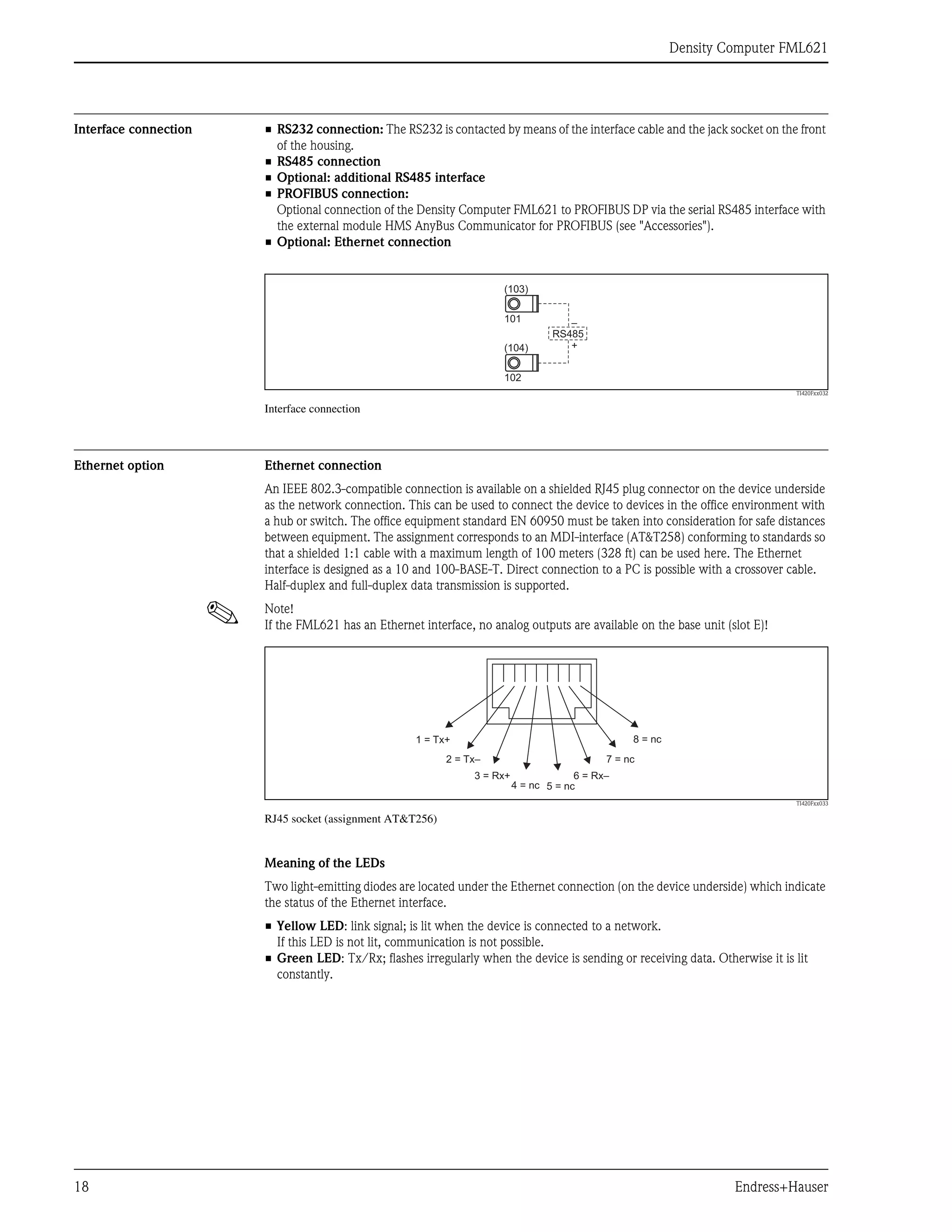
![Density Computer FML621
6 Endress+Hauser
Measuring system The FML621 supplies power directly to two-wire transmitters connected. Intrinsically safe inputs and
transmitter power supply units (for current cards) are optionally available for Ex-applications.
The inputs, outputs, limit values and display are configured, and the device is commissioned and serviced,
via 8 soft keys with the backlit dot-matrix display, using an RS232/RS485 interface or PC software
ReadWin® 2000. Online Help facilitates local operation.
The configurable change in color of the background illumination signals limit value violations or faults. The
function of the device can be extended at any time using extension cards. This also applies to use in the
hazardous area.
To use the telealarm function, we recommend common industrial modems that have an RS232 interface. The
measured values and events/alarms are coded in accordance with the serial protocol and then transmitted
(protocol can be requested).
! Note!
The number of inputs, outputs, relays and transmitter power supply units contained in the basic unit can be
individually extended using a maximum of three plug-in cards.
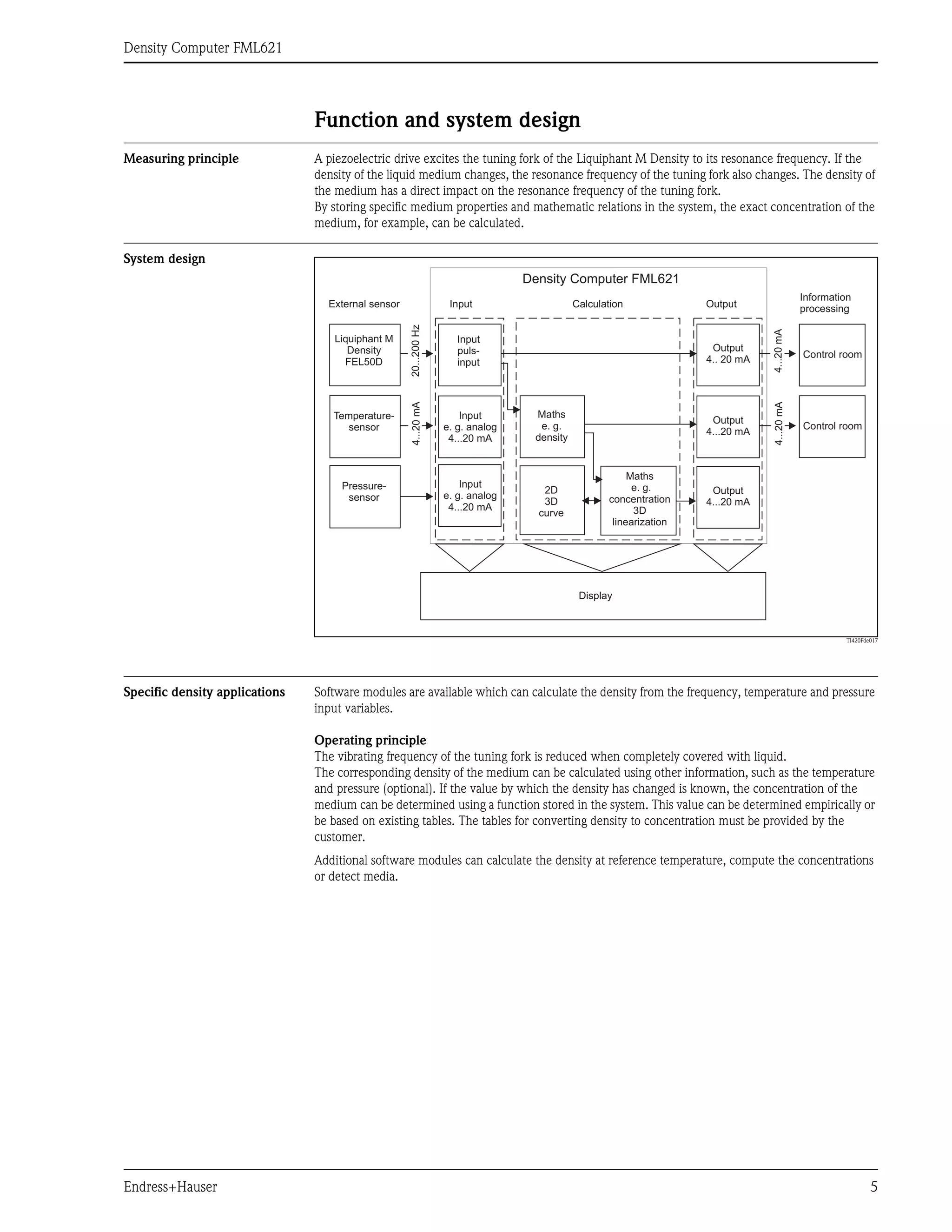
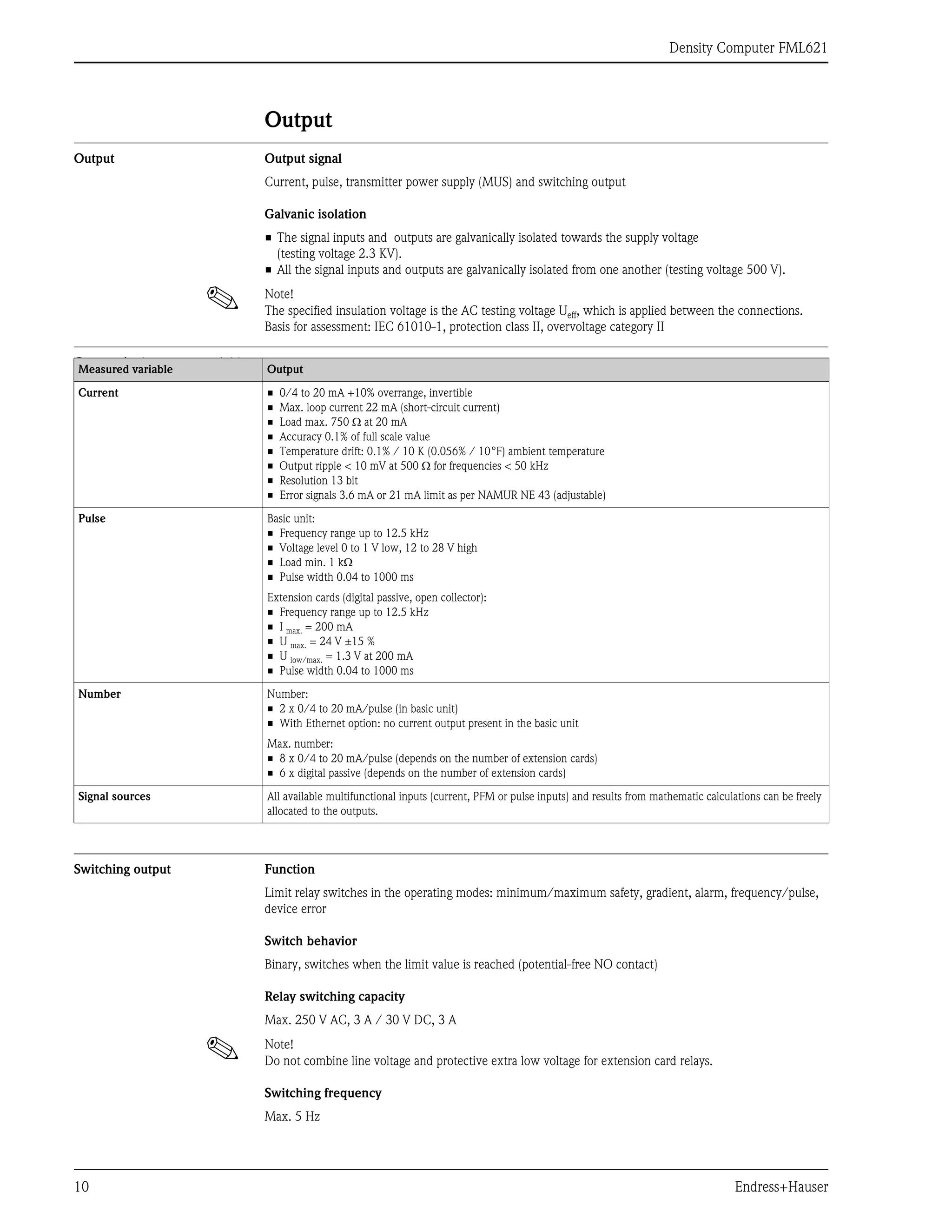
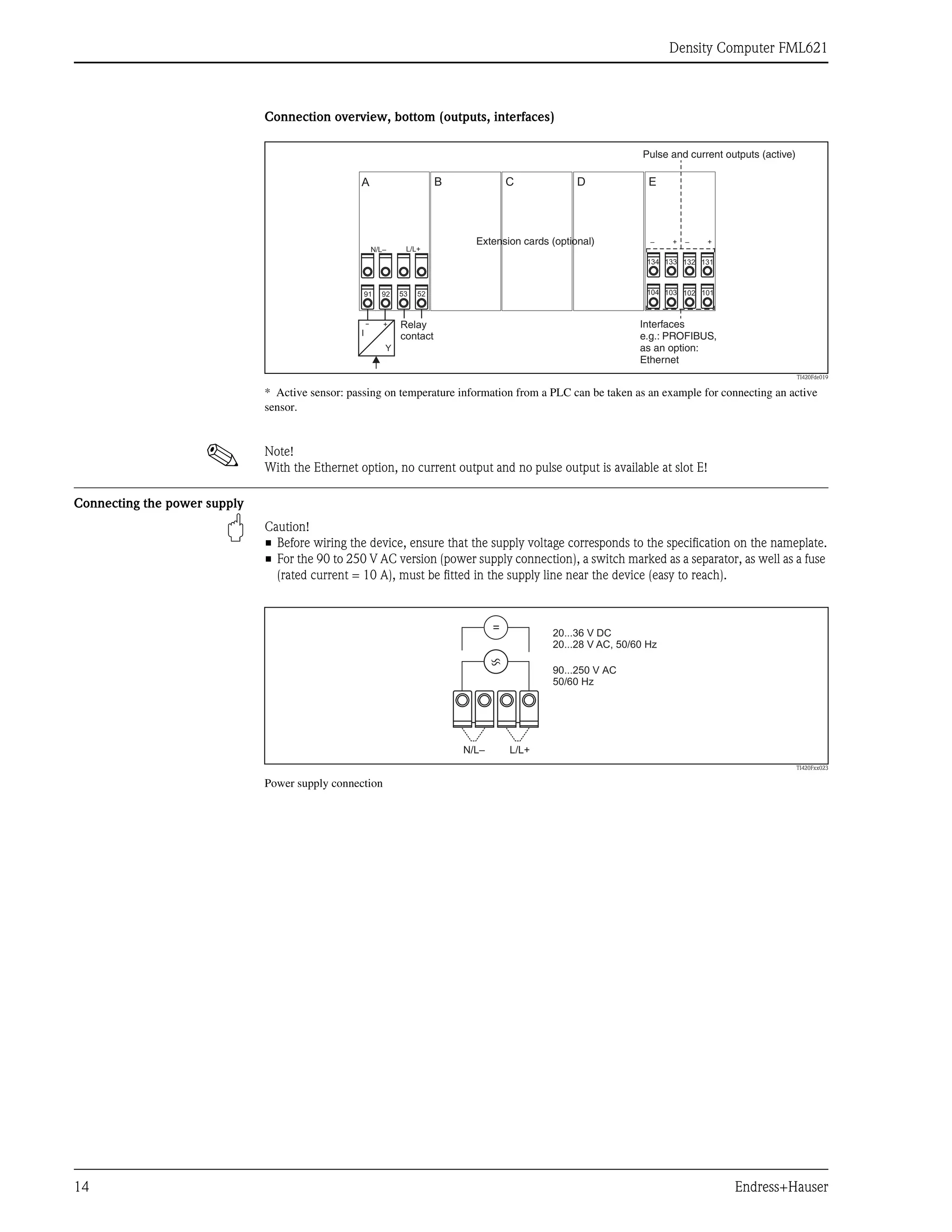
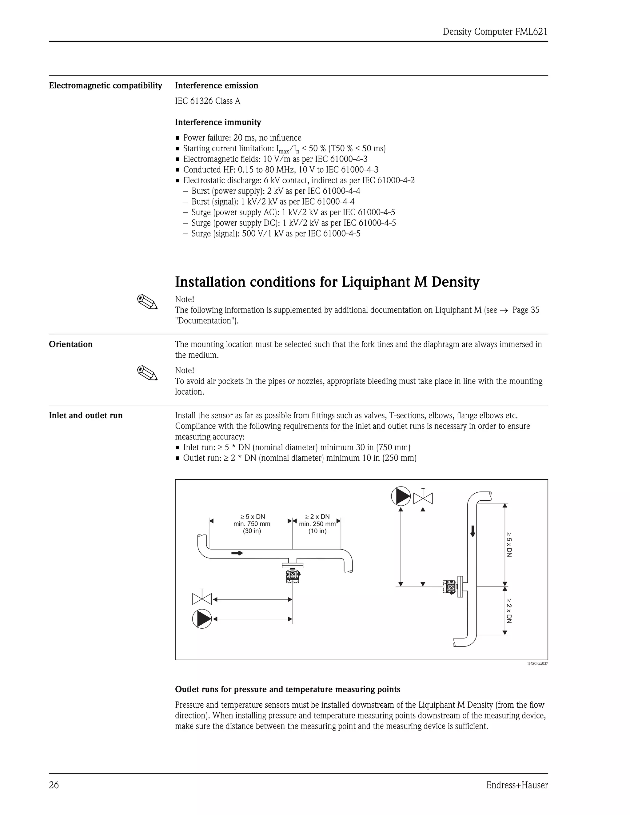
Reference density
In this module, the system refers back
to a reference temperature, such as
59°F or 70°F (15°C or 20°C).
It must be known how the density of
the medium changes at different
temperatures.
Concentration
Using density and concentration curves
already available or determined
empirically, the concentration can be
determined when substances are
continuously dissolved in a medium, for
example.
Medium detection
To be able to distinguish between two
media, the density function - as a
function of the temperature - can be
stored for several medias. In this way,
the system can distinguish between two
media or two different concentrations.
TI420Fde008
r
r
c
t
3
4
2
1
Process temperature
e. g. 30.5°C (87°F)
Calculation of reference
density e. g. 15°C (59°F)
Table [t]
r
Table , c [t]
r
Medium 1 [t]
Medium n [t]
r
r
Temperature
[°C/°F]
Temperature
[°C/°F]
Temperature
[°C/°F]
Density
[standard]
r
Concentration
Relay
Density
[g/cm³]
Density
[g/cm³]
Density
[g/cm³]](https://image.slidesharecdn.com/liquiphantmdensitydensitycontrollerfml621-endresshauserdatasheet-210818151602/75/Liquiphant-m-density-densitycontroller-fml621-endress-hauser-datasheet-6-2048.jpg)
![Density Computer FML621
Endress+Hauser 27
TI420Fxx039
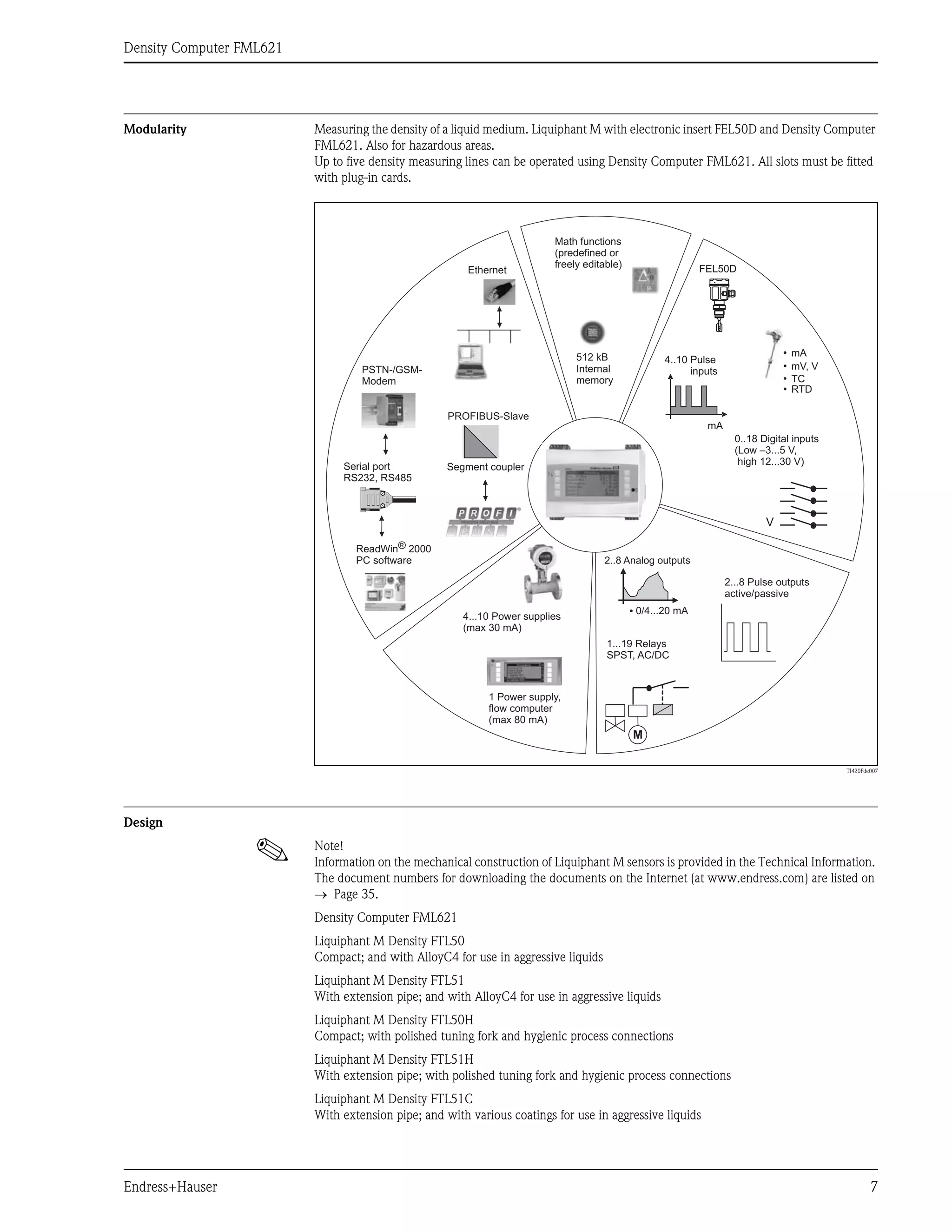
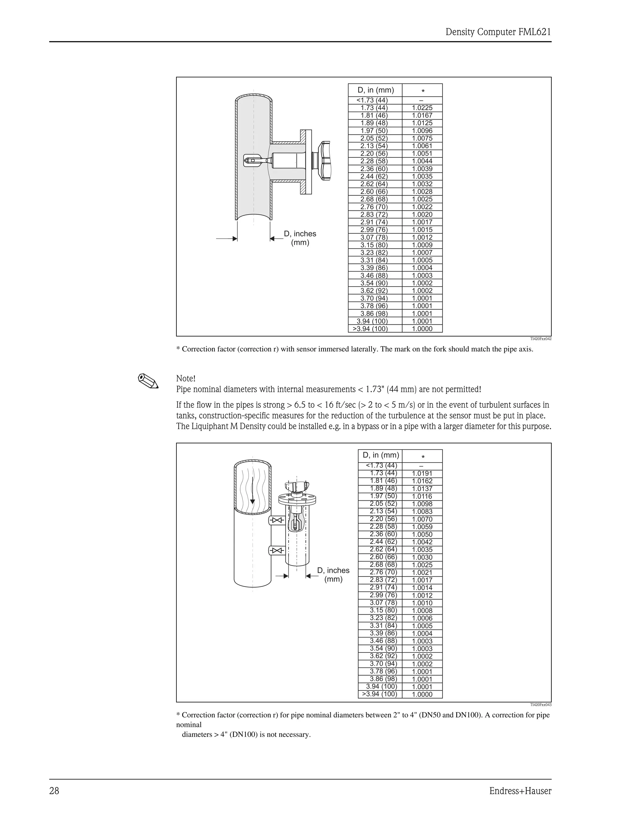
PT = Pressure measuring point
TT = Temperature measuring point
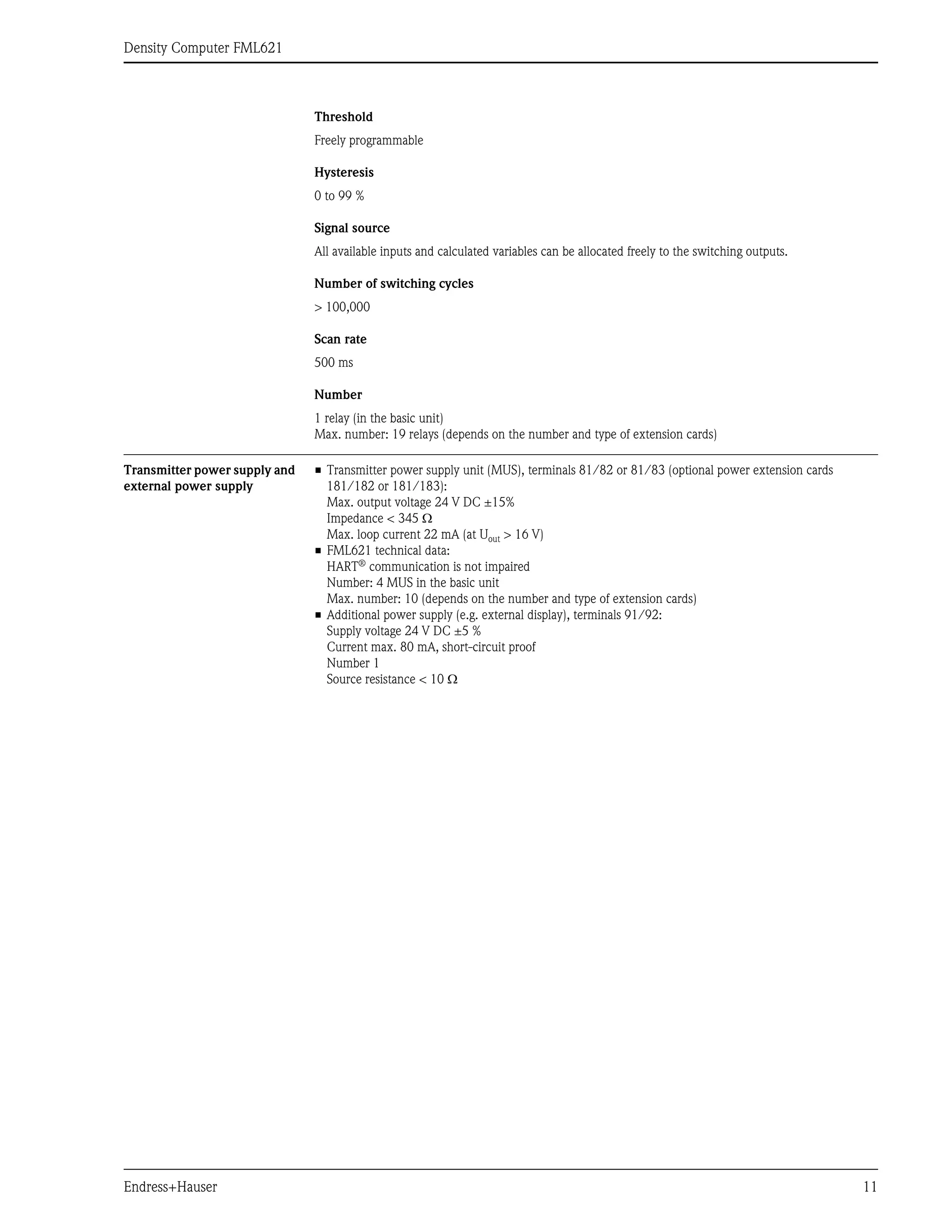
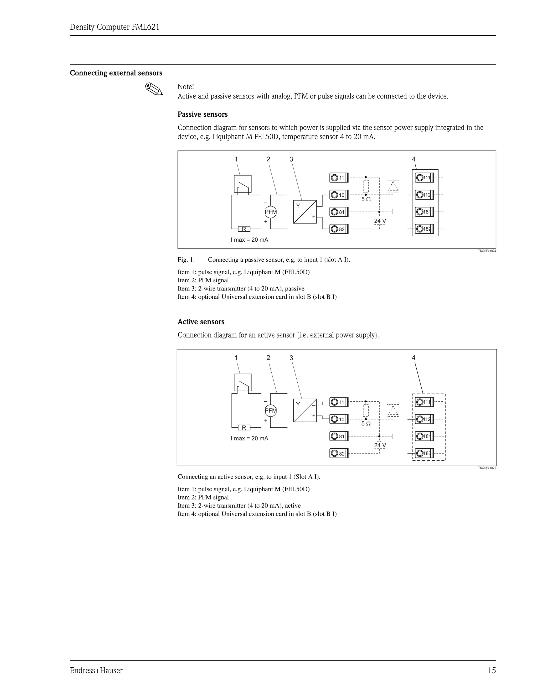
Mounting location and
correction factor (correction r)
The Liquiphant M can be installed in containers, tanks or pipes, for example.
! Note!
The following general conditions must be observed when selecting the correct mounting location:
• The vibrating tines of the Liquiphant M Density unit need room to vibrate at the mounting location. Even
with this small deflection, the medium is displaced or medium has to flow around the fork. If the distance
between the fork tines and the tank or pipe wall is very short, the measurement result is affected. This can
be balanced by entering a correction factor (correction r).
TI420Fxx040
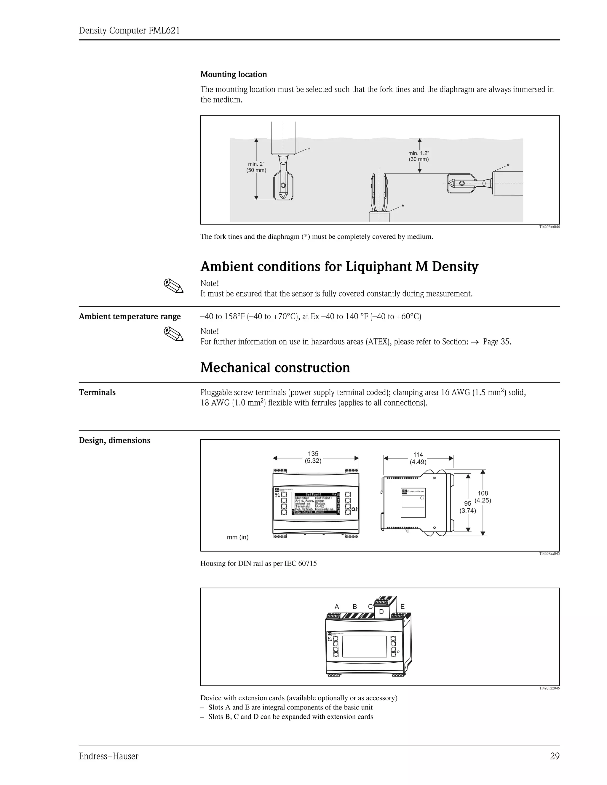
* Correction factor (correction r) with a distance of 0.47 to 1.57" (12 to 40 mm) between the tip of the fork tine and the
tank floor, for example.
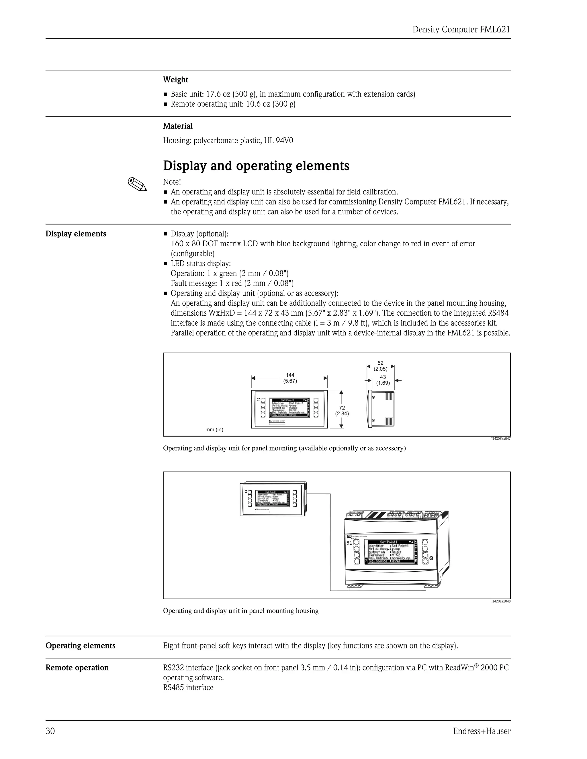
• In pipe internal fittings, the fork tines of the Liquiphant M must be aligned with the direction of flow.
Otherwise the measurement result can be distorted by vortexes and eddies.
– A mark on the process connection indicates the position of the fork tines.
Threaded connection = dot on the hexagon head; flange = two lines on the flange.
– The flow velocity of the medium may not exceed 6.5 ft/s (2 m/s) during operation.
• In tanks with an agitator, the Liquiphant must be aligned in the direction of flow. Otherwise the
measurement result can be distorted by vortexes and eddies.
TI420Fxx041
Fork tine alignment in direction of flow (note the mark on the Liquiphant M Density)
3...5 x DN
4...8 x DN
PT T
T
h, in (mm)
0.47 (12)
0.55 (14)
0.63 (16)
0.71 (18)
0.79 (20)
0.87 (22)
0.94 (24)
1.02 (26)
1.10 (28)
1.18 (30)
1.26 (32)
1.34 (34)
1.42 (36)
1.50 (38)
1.57 (40)
1.0026
1.0016
1.0011
1.0008
1.0006
1.0005
1.0004
1.0004
1.0004
1.0003
1.0003
1.0002
1.0001
1.0001
1.0000
*
h, inches [mm]](https://image.slidesharecdn.com/liquiphantmdensitydensitycontrollerfml621-endresshauserdatasheet-210818151602/75/Liquiphant-m-density-densitycontroller-fml621-endress-hauser-datasheet-27-2048.jpg)

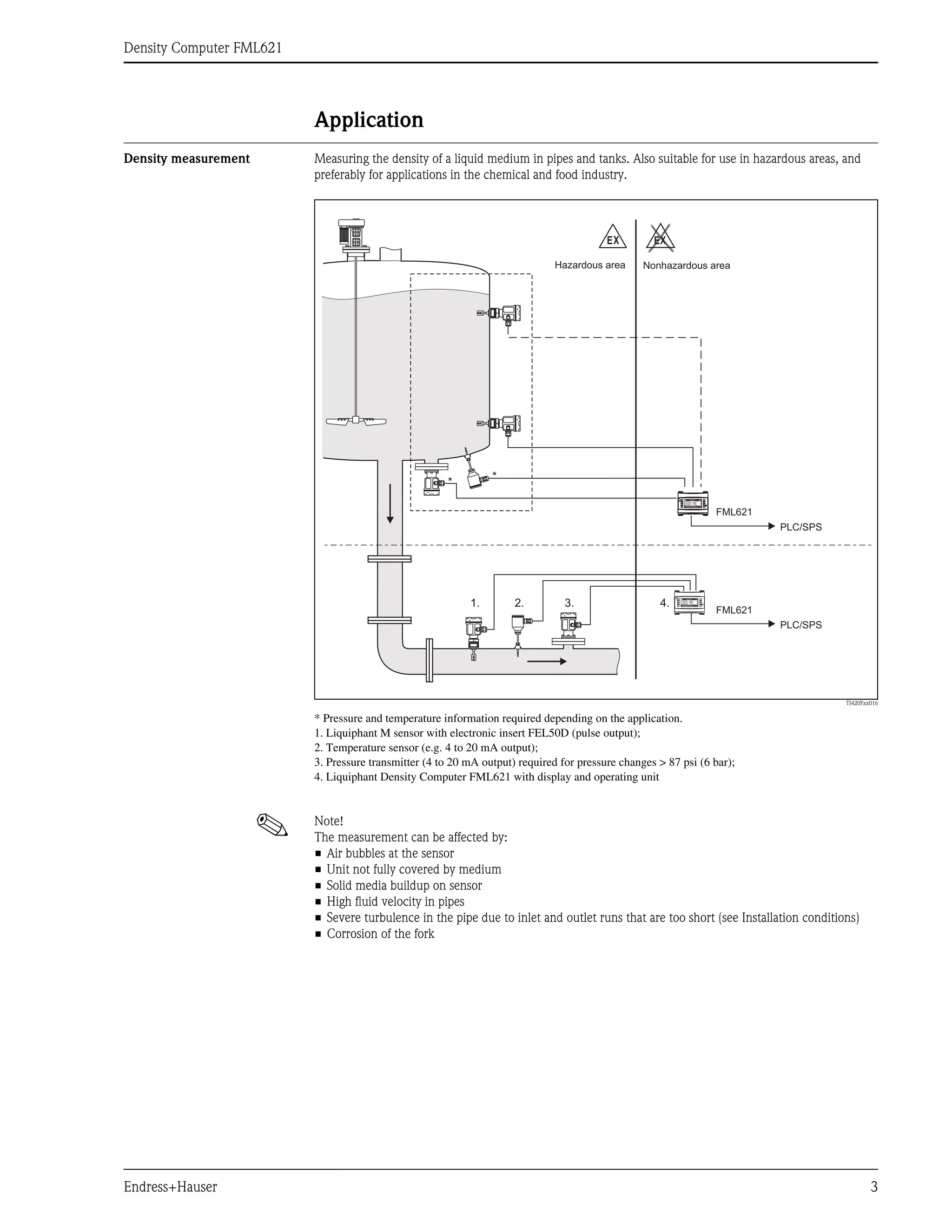
The document provides technical information about the Liquiphant M density measurement system with the FEL50D electronic insert and FML621 density computer, designed for hazardous areas and liquid media applications. It outlines the system's capabilities, including continuous density measurement, concentration calculation, and unit conversions, as well as various sensor options and benefits such as maintenance-free operation and hygienic compliance. Additionally, it discusses installation requirements, environmental considerations, and application examples for industries, including chemical and food sectors.


