
Download to read offline

![PROline Promag 23 P
Endress+Hauser 5
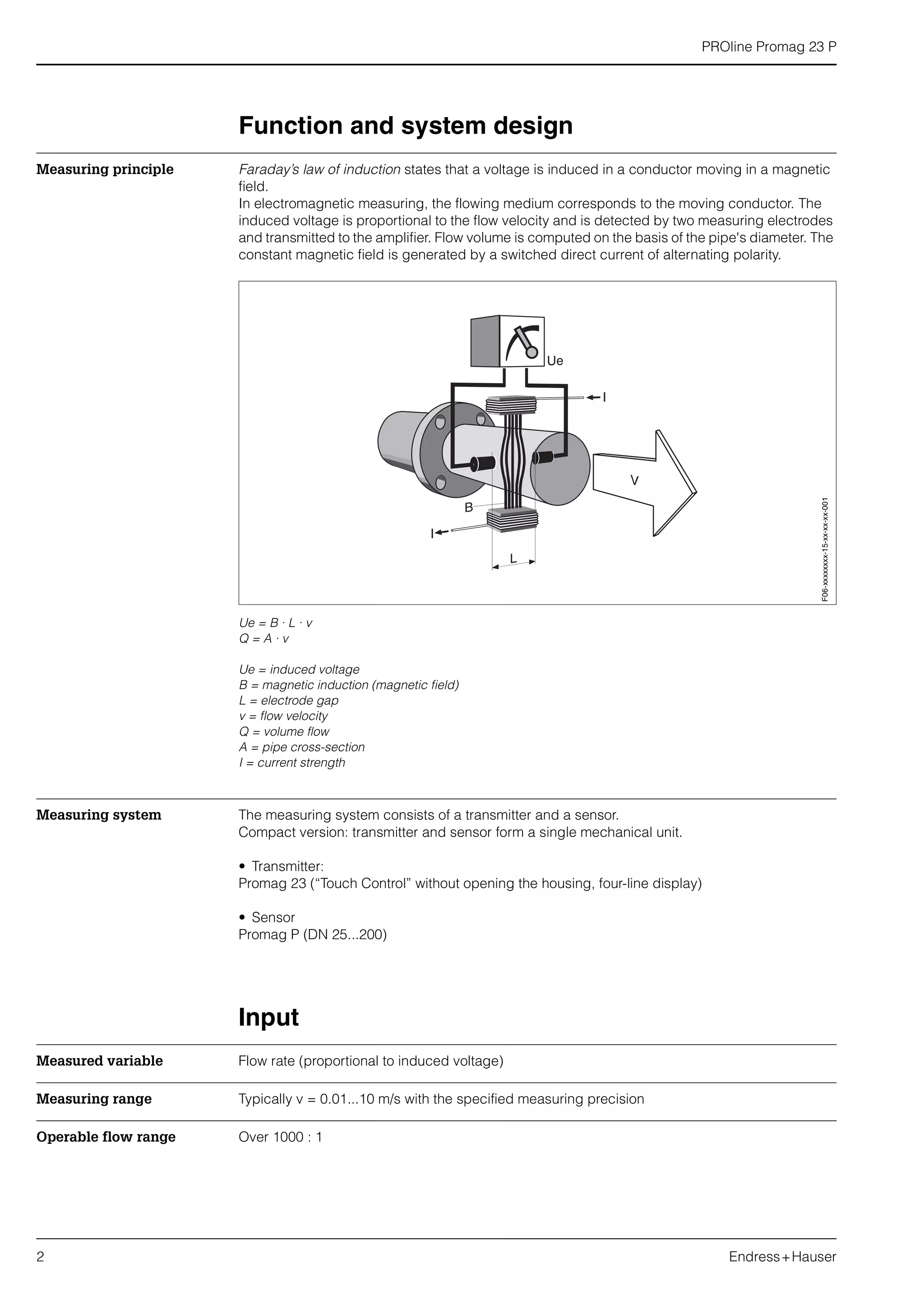
Load The load has to be calculated as follows:
Non Ex area:
Ex area (Ex i):
RL[Ω] = max. load resistance, load
(cable resistance)
US[V] = external supply voltage of 12...30 V DC
(outgoing supply voltage, transmitter supply unit)
UV[V] = min. supply voltage of 12 V DC
min. supply voltage of 13,9 V DC (Ex i)
(required supply voltage, transmitter)
IM[A] = max. signal transmission current
(failsafe mode current output: 22 mA max. current)
Note:
The minimum load resistance (RL) necessary for a data transfer via HART protocol by way of the
current signal cable is 250 Ω. The minimum external supply voltage (US) therefore has to be
17,5 V DC (non Ex).
Load at the analog current output (non Ex)
– RL – max. load resistance (with HART: min. 250 Ω)
– US – external supply voltage (non Ex)
Cable entry • Cable entry M20 x 1.5 (8...12 mm)
• Threads for cable entries, Pg 13.5 (5...15 mm), 1/2" NPT, G 1/2"
Cable specifications Use shielded cables.
Supply voltage Non Ex area: 12...30 V DC (with HART: 17.5...30 V DC)
Ex area (Ex i): 13.9...30 V DC (with HART: 19.4...30 V DC)
Power supply failure • T-DAT™ saves measuring system data if power supply fails
• S-DAT™: exchangeable data storage chip which stores the data of the sensor (nominal
diameter, serial number, calibration factor, zero point, etc.)
RL
Ω[ ]
US
V[ ] UV
V[ ]–
IM
A[ ]
--------------------------------------
US
V[ ] 12 V[ ]–
0 022 A[ ],
-------------------------------------= =
RL
Ω[ ]
US
V[ ] UV
V[ ]–
IM
A[ ]
--------------------------------------
US
V[ ] 13 9 V[ ],–
0 022 A[ ],
-------------------------------------------= =
F06-77xxxxxx-05-xx-xx-xx-000](https://image.slidesharecdn.com/prolinepromag23p-electromagneticflowmeter-130426221454-phpapp01/75/Proline-PROline-promag-23P-Electromagnetic-Flowmeter-5-2048.jpg)
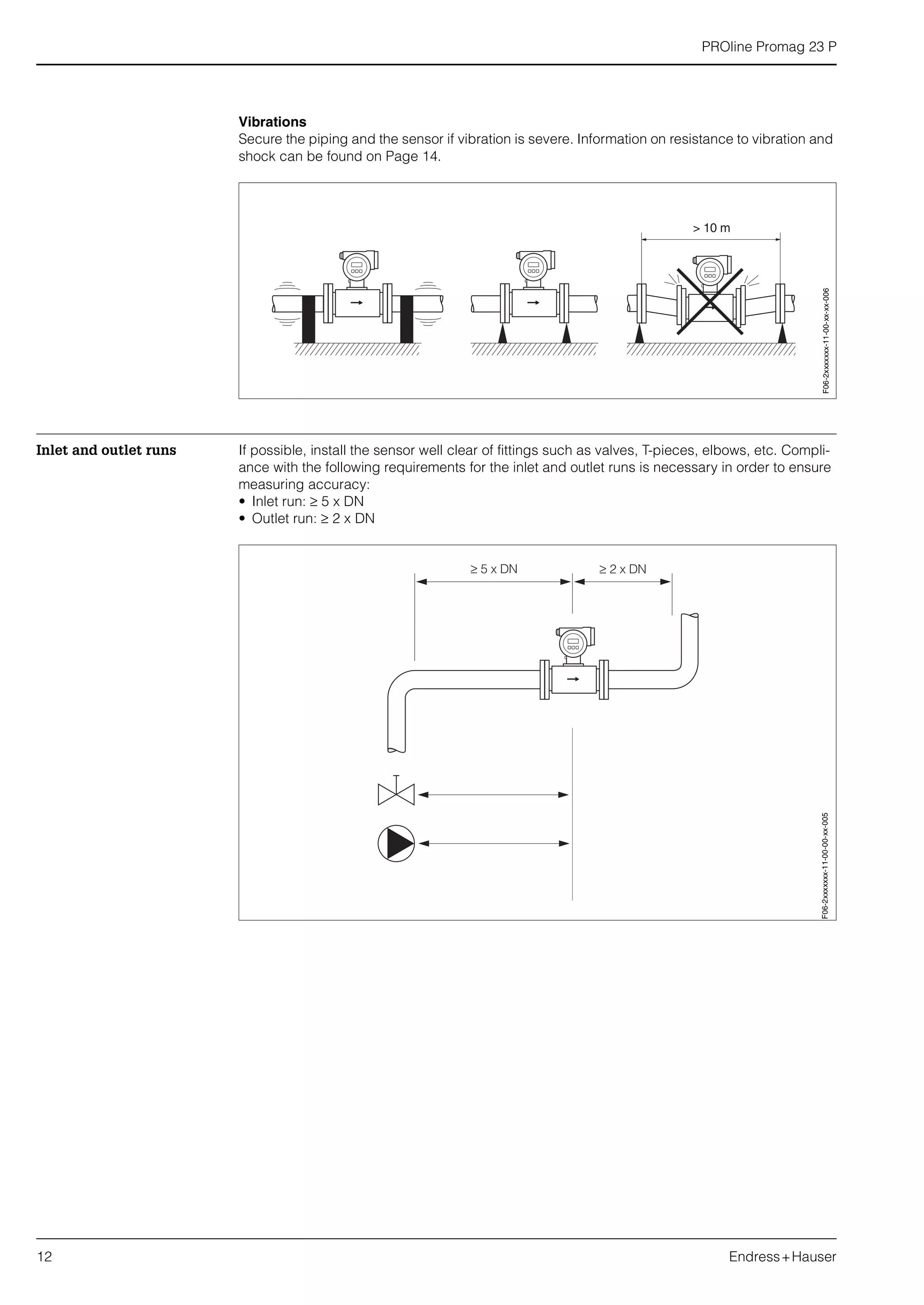
![PROline Promag 23 P
8 Endress+Hauser
Measuring accuracy
Reference operating
conditions
To DIN 19200 and VDI/VDE 2641:
• Medium temperature: +28 °C ± 2 K
• Ambient temperature: +22 °C ± 2 K
• Warm-up period: 30 minutes
Installation:
• Inlet run >10 x DN
• Outlet run > 5 x DN
• Sensor and transmitter grounded.
• Sensor centered relative to the pipe.
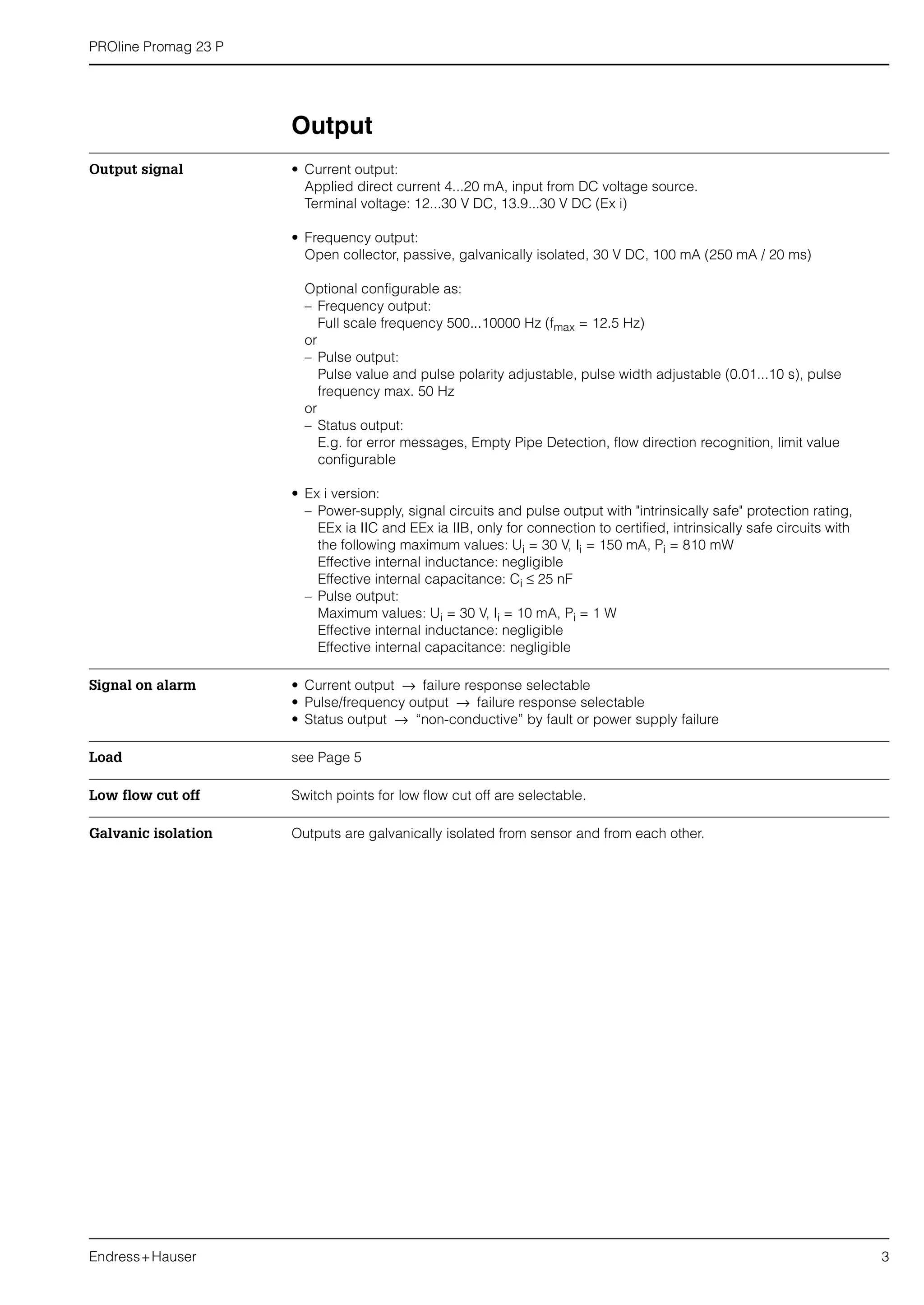
Max. measured error Signal output: ± 0.5% o.r. ± 4 mm/s (o.r. = of reading)
Supply voltage fluctuations have no effect within the specified range.
Max. measured error in [%] of reading
Repeatability max. ± 0.25% o.r. ± 2 mm/s (o.r. = of reading)
F06-2xxxxxxx-05-xx-xx-xx-001](https://image.slidesharecdn.com/prolinepromag23p-electromagneticflowmeter-130426221454-phpapp01/75/Proline-PROline-promag-23P-Electromagnetic-Flowmeter-8-2048.jpg)
![PROline Promag 23 P
14 Endress+Hauser
Ambient conditions
Ambient temperature −20...+60 °C
Install the device at a shady location. Avoid direct sunlight, particularly in warm climatic regions.
Storage temperature –10...+50 °C (preferably +20 °C)
Degree of protection IP 67 (NEMA 4X)
Shock and vibration
resistance
Acceleration up to 2 g by analogy with IEC 68-2-6
(High temperature version: no appropriate data available)
Electromagnetic
compatibility (EMC)
To EN 61326 and NAMUR recommendation NE 21
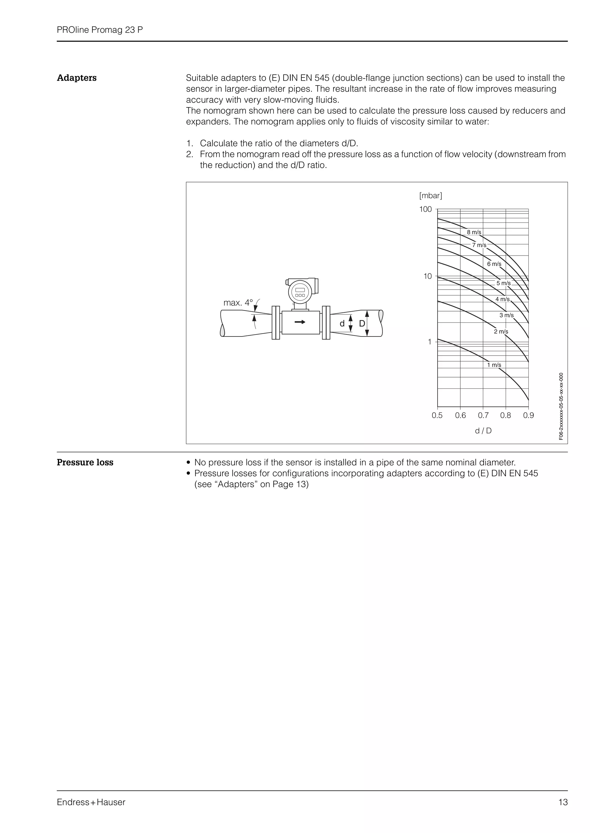
Process conditions
Medium temperature
range
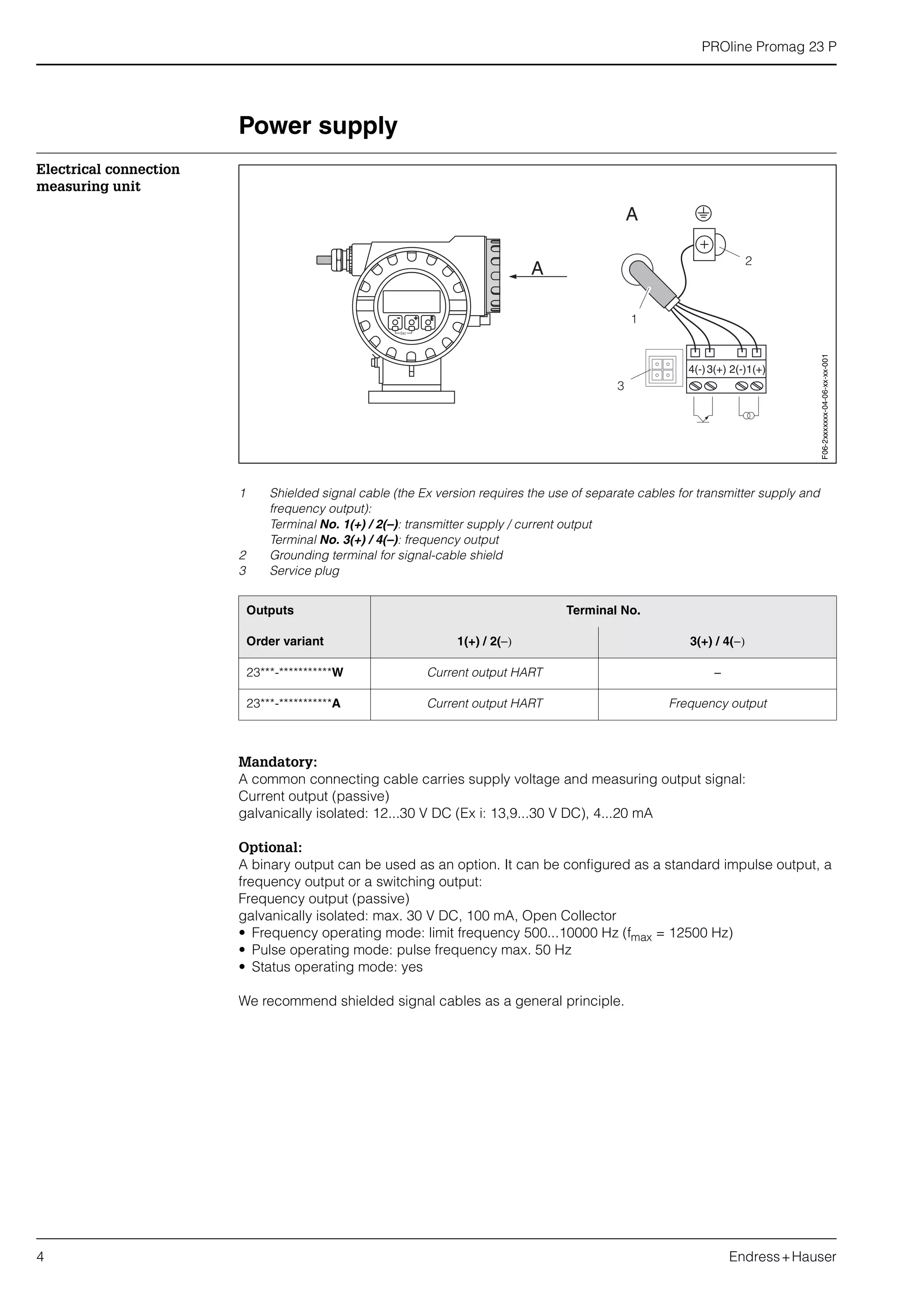
The permissible medium temperature depends on the measuring-tube lining:
• PTFE: –40...+130 °C
• PFA: –20...+180 °C (Ex i: –20...+150 °C)
for restrictions → see diagram
TA = ambient temperature
TF = medium temperature
HT = high temperature version, with insulation
Conductivity Minimum conductivity ≥ 50 µS/cm (for fluids in general)
0
0
-20 20
20
40
60
TA [°C]
40 60 80
TF [°C]
100 120 140 160 180
HT
PFA
PTFE
F06-2xPxxxxx-05-xx-xx-xx-000](https://image.slidesharecdn.com/prolinepromag23p-electromagneticflowmeter-130426221454-phpapp01/75/Proline-PROline-promag-23P-Electromagnetic-Flowmeter-14-2048.jpg)
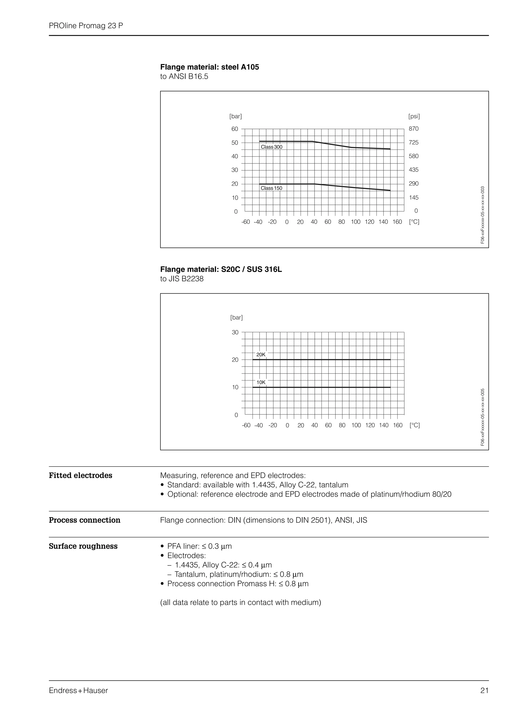
![PROline Promag 23 P
Endress+Hauser 15
Medium pressure range
(nominal pressure)
DIN 2501:
PN 10 (DN 200)
PN 16 (DN 65...200)
PN 25 (DN 200)
PN 40 (DN 25...150)
ANSI B16.5:
Class 150 (1...8")
Class 300 (1...8")
JIS B2238:
10K (DN 50...200)
20K (DN 25...200)
Pressure tightness
(liner)
Nominal
diameter
Measuring tube
lining
Resistance to partial vacuum of measuring tube lining
Limit values for abs. pressure [mbar] at various fluid temperatures
[mm] [inch] 25 °C 80 °C 100 °C 130 °C 150 °C 180 °C
25 1" PTFE / PFA 0 / 0 0 / 0 0 / 0 100 / 0 − / 0 − / 0
32 − PTFE / PFA 0 / 0 0 / 0 0 / 0 100 / 0 − / 0 − / 0
40 1 1/2" PTFE / PFA 0 / 0 0 / 0 0 / 0 100 / 0 − / 0 − / 0
50 2" PTFE / PFA 0 / 0 0 / 0 0 / 0 100 / 0 − / 0 − / 0
65 − PTFE / PFA 0 / 0 * 40 / 0 130 / 0 − / 0 − / 0
80 3" PTFE / PFA 0 / 0 * 40 / 0 130 / 0 − / 0 − / 0
100 4" PTFE / PFA 0 / 0 * 135 / 0 170 / 0 − / 0 − / 0
125 − PTFE / PFA 135 / 0 * 240 / 0 385 / 0 − / 0 − / 0
150 6" PTFE / PFA 135 / 0 * 240 / 0 385 / 0 − / 0 − / 0
200 8" PTFE / PFA 200 / 0 * 290 / 0 410 / 0 − / 0 − / 0
* No value can be specified.](https://image.slidesharecdn.com/prolinepromag23p-electromagneticflowmeter-130426221454-phpapp01/75/Proline-PROline-promag-23P-Electromagnetic-Flowmeter-15-2048.jpg)
![PROline Promag 23 P
16 Endress+Hauser
Limiting flow The diameter of the pipe and the flow rate determine the nominal diameter of the sensor. The opti-
mum velocity of flow is 2...3 m/s. The velocity of flow (v), moreover, has to be matched to the phys-
ical properties of the medium:
• v < 2 m/s: for abrasive mediums
• v > 2 m/s: for accretive mediums
Flow characteristics of Promag P (SI units)
Nominal
diameter
Recommended
flow rate
Factory settings
[mm] [inch]
Min./max. full scale value
(v ~ 0.3 or 10 m/s)
Full scale value
(v ~ 2.5 m/s)
Pulse weighting
(~ 2 pulse/s)
Creepage
(v ~ 0.04 m/s)
25 1" 9…300 dm3
/min 75 dm3
/min 0.50 dm3
1 dm3
/min
32 1 1/4" 15…500 dm3
/min 125 dm3
/min 1.00 dm3
2 dm3
/min
40 1 1/2" 25…700 dm3
/min 200 dm3
/min 1.50 dm3
3 dm3
/min
50 2" 35…1100 dm3
/min 300 dm3
/min 2.50 dm3
5 dm3
/min
65 2 1/2" 60…2000 dm3
/min 500 dm3
/min 5.00 dm3
8 dm3
/min
80 3" 90…3000 dm3
/min 750 dm3
/min 5.00 dm3
12 dm3
/min
100 4" 145…4700 dm3
/min 1200 dm3
/min 10.00 dm3
20 dm3
/min
125 5" 220…7500 dm3
/min 1850 dm3
/min 15.00 dm3
30 dm3
/min
150 6" 20…600 m3
/h 150 m3
/h 0.025 m3
2.5 m3
/h
200 8" 35…1100 m3
/h 300 m3
/h 0.05 m3
5.0 m3
/h
Flow characteristics of Promag P (US units)
Nominal
diameter
Recommended
flow rate
Factory settings
[inch] [mm]
Min./max. full scale value
(v ~ 0.3 or ~ 10 m/s)
Full scale value
(v ~ 2.5 m/s)
Pulse weighting
(~ 2 pulse/s)
Creepage
(v ~ 0.04 m/s)
1" 25 2.5…80 gal/min 18 gal/min 0.20 gal 0.25 gal/min
1 1/4" 32 4…130 gal/min 30 gal/min 0.20 gal 0.50 gal/min
1 1/2" 40 7…190 gal/min 50 gal/min 0.50 gal 0.75 gal/min
2" 50 10…300 gal/min 75 gal/min 0.50 gal 1.25 gal/min
2 1/2" 65 16…500 gal/min 130 gal/min 1 gal 2.0 gal/min
3" 80 24…800 gal/min 200 gal/min 2 gal 2.5 gal/min
4" 100 40…1250 gal/min 300 gal/min 2 gal 4.0 gal/min
5" 125 60…1950 gal/min 450 gal/min 5 gal 7.0 gal/min
6" 150 90…2650 gal/min 600 gal/min 5 gal 12 gal/min
8" 200 155…4850 gal/min 1200 gal/min 10 gal 15 gal/min](https://image.slidesharecdn.com/prolinepromag23p-electromagneticflowmeter-130426221454-phpapp01/75/Proline-PROline-promag-23P-Electromagnetic-Flowmeter-16-2048.jpg)
![PROline Promag 23 P
Endress+Hauser 17
Mechanical construction
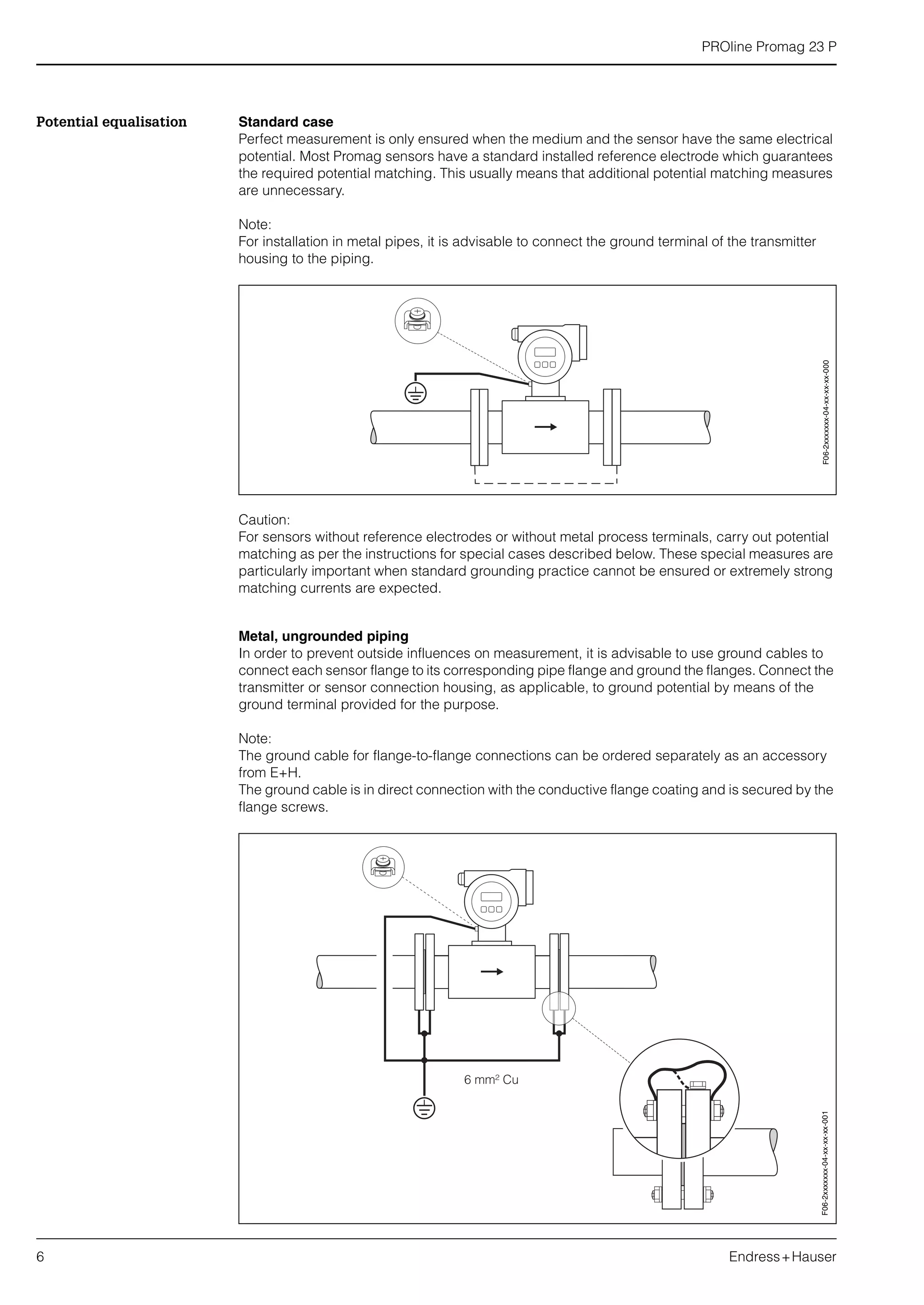
Design / dimensions Promag P / DN 25...200
Promag P / DN ≤ 300 (high temperature version)
Dimensions of high temperature version (Promag P)
Dimensions A1, B1 = A, B of standard version plus 110 mm
DN L A B C K E
DIN
[mm]
ANSI
[inch] [mm] [mm] [mm] [mm] [mm] [mm]
25 1" 200 365 281 84 120 94
32 − 200 365 281 84 120 94
40 1 1/2" 200 365 281 84 120 94
50 2" 200 365 281 84 120 94
65 − 200 415 306 109 180 94
80 3" 200 415 306 109 180 94
100 4" 250 415 306 109 180 94
125 − 250 496 346 150 260 140
150 6" 300 496 346 150 260 140
200 8" 350 551 371 180 324 156
The fitting length (L) is always the same, regardless of the pressure rating. F06-23Fxxxxx-06-00-xx-xx-000
A1
B1
110
Esc
E- +
F06-23Pxxxxx-06-00-xx-xx-000](https://image.slidesharecdn.com/prolinepromag23p-electromagneticflowmeter-130426221454-phpapp01/75/Proline-PROline-promag-23P-Electromagnetic-Flowmeter-17-2048.jpg)
![PROline Promag 23 P
18 Endress+Hauser
Ground disk (DN 25...200)
Dimensions of ground disks (Promag P / DN 25…200)
DN 1)
A B D H
DIN
[mm]
ANSI
[inch] [mm] [mm] [mm] [mm]
25 1" 30 62 77.5 87.5
32 − 38.5 80 87.5 94.5
40 1 1/2" 44.5 82 101 103
50 2" 56.5 101 115.5 108
65 − 72.5 121 131.5 118
80 3" 85 131 154.5 135
100 4" 110 156 186.5 153
125 − 135 187 206.5 160
150 6" 163 217 256 184
200 8" 210.5 267 288 205
1)
Ground disks can be used for all suppliable flange standards / pressure ratings.
15
10
H
Ø B
Ø A
Ø D
Ø
6.5
2
F06-xxxxxxxx-06-09-00-xx-001](https://image.slidesharecdn.com/prolinepromag23p-electromagneticflowmeter-130426221454-phpapp01/75/Proline-PROline-promag-23P-Electromagnetic-Flowmeter-18-2048.jpg)
![PROline Promag 23 P
Endress+Hauser 19
Weight
Materials Transmitter housing:
Powder-coated die-cast aluminum
Sensor housing:
Powder-coated die-cast aluminum
Measuring tube:
Stainless steel 1.4301 or 1.4306/304L
(with non-stainless flange material with AI/Zn protective coating)
Flanges:
• DIN : Stainless steel 1.4571, ST37 / FE 410W B (with Al/Zn protective coating)
• ANSI: A105, 316L (with Al/Zn protective coating)
• JIS: S20C, SUS 316L (with Al/Zn protective coating)
Ground disks:
• Standard: 1.4435/316L
• Option: Alloy C-22
Electrodes:
• Standard: 1.4435, platinum/rhodium 80/20
• Option: Alloy C-22, tantalum
Seals to DIN 2690
Weight data of Promag P in kg
Nominal diameter Compact version
[mm] [inch] DIN ANSI
25 1"
PN40
7,3
Class150
7,3
32 1 1/4" 8,0 –
40 1 1/2" 9,4 9,4
50 2" 10,6 10,6
65 2 1/2"
PN16
12,0 –
80 3" 14,0 14,0
100 4" 16,0 16,0
125 5" 21,5 –
150 6" 25,5 25,5
200 8"
PN10
45 45
High temperature version: +1.5 kg
(Weight data valid for standard pressure ratings and without packaging material)
TI 049D/06/en/05.00
FM+SGML 5.5](https://image.slidesharecdn.com/prolinepromag23p-electromagneticflowmeter-130426221454-phpapp01/75/Proline-PROline-promag-23P-Electromagnetic-Flowmeter-19-2048.jpg)
![PROline Promag 23 P
20 Endress+Hauser
Material load curves Flange material: steel 37
to DIN 2413 and 2505
Flange material: stainless steel 1.4571
to DIN 2413 and 2505
Flange material: steel 316L
to ANSI B16.5
0
5
10
15
20
25
PN25
PN16
PN10
35
30
40
PN40
[bar]
-60 -40 -20 0 20 40 60 80 100 120 140 160 [°C]
F06-xxFxxxxx-05-xx-xx-xx-006
0
5
10
15
20
25
PN25
PN16
PN10
35
30
40
PN40
[bar]
-60 -40 -20 0 20 40 60 80 100 120 140 160 [°C]
F06-xxFxxxxx-05-xx-xx-xx-007F06-xxFxxxxx-05-xx-xx-xx-002](https://image.slidesharecdn.com/prolinepromag23p-electromagneticflowmeter-130426221454-phpapp01/75/Proline-PROline-promag-23P-Electromagnetic-Flowmeter-20-2048.jpg)
The document details the technical specifications of the Proline Promag 23 P electromagnetic flow measuring system, suitable for chemical or process applications with various features such as robust housing, touch control operation, HART communication, and compatibility with a range of fluids. It outlines the measuring principle based on Faraday’s Law, installation requirements, output signals, installation conditions, and temperature ranges for the measuring tube lining materials. Additionally, it provides guidelines for potential equalization, grounding, and best practices to ensure accurate measurement and operation in various settings.


![Vibe Coding vs. Spec-Driven Development [Free Meetup]](https://cdn.slidesharecdn.com/ss_thumbnails/vibecodingvsspecdrivendevelopment-251209105622-43f455e7-thumbnail.jpg?width=640&height=640&fit=bounds)


