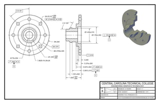
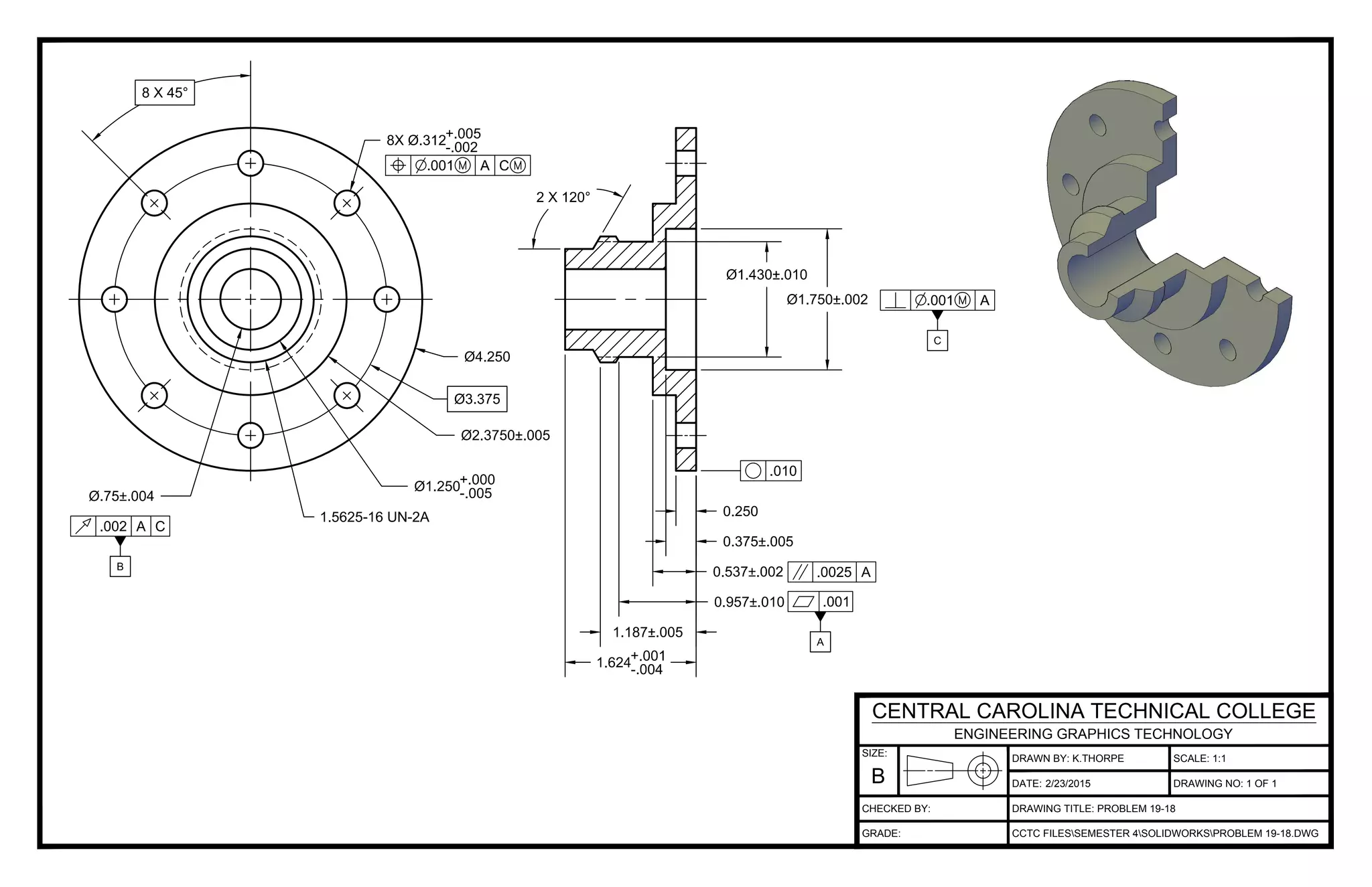
This drawing was created by K. Thorpe for Problem 19-18 on February 23, 2015 at a scale of 1:1. The drawing was created using the CCTC FILES\SEMESTER 4\SOLIDWORKS\PROBLEM 19-18.DWG file and is drawing number 1 of 1.
This technical drawing shows the dimensions of a 3D model of a queen chess piece. It includes dimensions for the height, width, angles, and diameters of circular cutouts. The drawing title is "Queen" and it was drawn by K. Thorpe on September 29, 2014 for a class project at Central Carolina Technical College.
This drawing shows the dimensions of a board with a rectangular shape. The board is 111 centimeters long and 29.25 centimeters wide. It was drawn by K. Thorpe on September 23, 2014 at a metric scale for Central Carolina Technical College's Engineering Graphics Technology program.
This technical drawing shows a plug valve design with dimensions. The plug valve features a cylindrical plug that fits inside a tapered valve body. Key dimensions include the plug diameter of 16mm, valve body diameters of 26.5mm and 38.5mm, and plug length of 30mm. The drawing was created by K. Thorpe for a class project at Central Carolina Technical College and checked for accuracy.
This drawing shows the dimensions of a 3D model of a king chess piece. It includes dimensions for the height, width, and thickness at various points on the piece. Angles and hole diameters are also specified. The drawing title is "King", it was drawn by K. Thorpe on an unspecified date, and will be 3D printed at a scale of 2:1 using CCTC files.
This drawing shows the housing component of a plug valve. It includes dimensions for the outer diameter, holes, and ribs. The housing has an outer diameter of 88mm and contains three evenly spaced ribs with a radius of 2mm on the interior. Smaller holes of varying diameters are placed throughout for connections. The title, scale, and other identifying information are present to specify the part and conform to engineering drawing standards.
This technical drawing shows the details of an angle slide, including its dimensions and tolerances. It was drawn by K. Thorpe for a class at Central Carolina Technical College. The angle slide has various sized slots and holes, with most features rounded or filleted to a radius of 0.125 inches except where noted otherwise.
This drawing document provides assembly details for a plug valve. It was drawn by K. Thorpe on December 1, 2014 at a metric scale for Central Carolina Technical College's Engineering Graphics Technology program. The drawing is numbered 1 of 6.
This drawing document provides assembly details for a trolley. It was drawn by K. Thorpe on December 1, 2014 at an unspecified scale for Central Carolina Technical College's Engineering Graphics Technology program. The drawing is numbered 1 of 8.
The document discusses conditional generative adversarial networks (GANs) for image-to-image translation tasks. It presents the conditional CycleGAN model which uses cycle consistency loss to learn mappings between domains without paired training examples. The model consists of generators and discriminators trained in an adversarial manner to translate images from one domain to another and back again.
The document discusses project scheduling techniques like PERT and CPM. It provides an example of using these methods to schedule the building of an elaborate parade float. Key activities, durations, and dependencies are laid out. Calculations are shown to determine the critical path, earliest and latest start/finish times, and project completion time. For activities with uncertain durations, a three-time estimate approach is described to model duration as a distribution and calculate the probability of on-time completion.
This document contains a list of tasks with durations and a critical path method calculation. It shows 14 tasks from A3 to N7 with various durations that make up a project planned to take 25 days to complete. The critical path is calculated to be tasks A, D, I, N.
PERT and CPM are project scheduling techniques. PERT was developed by the U.S. Navy for complex projects with uncertain times, while CPM was developed by DuPont and Remington Rand for industrial projects with known times. An example project schedule is provided showing activities, predecessors, times, earliest and latest start and finish times, slack, and identifying the critical path.
This engineering drawing document contains details for a plexyglass coil component including:
- Views A-A and B-B showing scale dimensions of the overall component and a close-up of area B.
- View C-C providing an enlarged scale view of area C.
- Dimensioned details for five sections labeled A through E with notes on chamfers and tolerances.
- Title block identifying the component, scale used, document number and approval information.
This technical drawing shows the side plate component of a trolley system, including its dimensions and hole placement. It was drawn by K. Thorpe on December 8, 2014 for Central Carolina Technical College's Engineering Graphics Technology program. The side plate is approximately 8 inches long and 7 inches high with various holes and cutouts as indicated on the scale drawing.
This document discusses project management techniques for network analysis, specifically Critical Path Method (CPM) and Program Evaluation and Review Technique (PERT). It defines key concepts like activities, events, predecessors, successors, critical paths. It provides an example network diagram for a project with activities and calculates the critical path, earliest start/finish times, latest start/finish times, and float. CPM and PERT are important techniques for managing complex projects with sequential and parallel activities.
This document contains engineering drawings of cross sections for a 3D model. Section B-B shows the dimensions and features of one cross sectional view at a 1:1 scale. Section C-C shows another cross sectional view of the same 3D model with different dimensions and including rounded edges and slots. Both views are labeled with the student name, drawing name, scale, and date they were created using Autodesk design software.
The document contains several technical drawings produced by an Autodesk educational product. Each page displays geometric shapes with numerical dimensions, and includes a student name, drawing name, scale, and date in the header. The drawings were created by a student named lee2075 between October 21-25, 2010 using Autodesk design software for educational purposes.
The document contains technical drawings from a student named depau9827 created using an Autodesk educational product. There are drawings titled "Sketching problem-3" through "Sketching problem-11" dated from October 21-25, 2010 with various scales listed. The drawings appear to be practice sketches done by the student to learn technical drawing skills.
The document contains a parts list and drawings for a model train assembly. It lists 9 parts needed for the train including the train body, cow catcher, smoke stack, wheels, and linkage arms. Accompanying the parts list are technical drawings with dimensions for each individual part.
This technical drawing shows the side plate of a trolley, including dimensions and hole specifications. It was drawn by K. Thorpe on October 2, 2014 for Central Carolina Technical College's Engineering Graphics Technology program. The drawing is number 3 of 8 for the trolley project.
This drawing shows details of a trolley wheel, including dimensions and notes. It was drawn by K. Thorpe on October 30, 2014 for Central Carolina Technical College's Engineering Graphics Technology program. The drawing depicts the profile of a wheel with various radii, diameters, and other geometric specifications.
This technical drawing shows the dimensions for a trolley axle and wheel assembly with two snap rings to hold the axle in place and four snap rings for the wheels. It was drawn by K. Thorpe on November 5, 2014 for a class project at Central Carolina Technical College.
This drawing shows a departure ball bearing for a trolley with 8 evenly spaced balls. The drawing specifies the dimensions of the balls and outer raceway of the bearing which has 2 balls required and was drawn by K. Thorpe for a class project at Central Carolina Technical College.
The drawing depicts an axle for a trolley with dimensions, including an overall length of 2.875 inches, diameter of 0.875 inches, and thickness of 0.1040 inches. It was drawn by K. Thorpe for Central Carolina Technical College's Engineering Graphics Technology course, and is drawing number 5 of 8 in the Trolley - Axle series.
This technical drawing shows dimensions and specifications for a clamp plug for an any angle tool vice. It includes dimensions for various angles and diameters of the plug. The drawing also lists the date it was created, the scale, the title, associated CAD file, and the school and program where it was created.
This technical drawing shows dimensions for an eccentric any angle tool vice. Key dimensions include the diameter and thickness of various cylindrical and circular features ranging from .125 to 1.281 units. The drawing also lists the drafter, date, scale, title, CAD file information, and school where it was created.
This technical drawing shows dimensions for a lower plate of an any angle tool vice. It includes labeled dimensions for holes, radii, angles, and features of the plate. The drawing title identifies it as the lower plate of an any angle tool vice, and it was drawn by C.J. Ingram for Central Carolina Technical College's Engineering Graphics Technology program.
This drawing shows dimensions for an angle tool vice saddle, including hole diameters, radii, lengths, and labeling. Key features include dimensions ranging from 0.125 to 6.5, holes labeled with diameters and depths, fillets and rounds of 0.125 radius, and notes specifying the date, scale, title, file path and number. The drawing was created by C.J. Ingram for Central Carolina Technical College's Engineering Graphics Technology program.
This drawing shows a compound tool holder with various dimensions and features including holes, diameters, angles, chamfers, and notes. It was drawn by C.J. Ingram for Central Carolina Technical College's Engineering Graphics Technology program and provides the details to manufacture the tool holder.
This document contains technical drawings and specifications for an upper compound member including dimensions, tolerances, notes and labels such as the title, scale, part number, date, and initials of the designer and checker. Key specifications include an outside diameter of 1.75 inches, a radius of 1.999 inches, a length of 15.1 inches, angles of 40 and 15 degrees, and thread specifications.
This technical drawing shows dimensions for an upper plate of an any angle tool vice. It includes labeled dimensions for holes, radii, angles, and features of the plate with sizes ranging from 0.063 to 3.5 inches. The drawing also lists the date, scale, title, CAD file information, drawing number, and notes that it was drawn and checked by students at Central Carolina Technical College.
This technical drawing shows dimensions for a gear puller arm with various radii, lengths, angles, and notes. Key specifications include lengths of 2.8750, 2.8400, and 1.1250 inches, an angle of 25 degrees, radii of 0.4060 and 0.0300 inches, and notes to fillet all edges but not both sides of a specific dimension. The drawing was created by K. Thorpe on November 19, 2014 for Central Carolina Technical College's engineering graphics technology course.
This drawing shows a gear puller tool used to remove cotter pins. It was drawn by K. Thorpe on November 20, 2014 at a scale of 8:1. The gear puller has several rounded features including the jaws that grip the gear, with dimensions provided in inches. It will be used to assist the removal of cotter pins from mechanical components.
The drawing depicts a gear puller with clevis pin attachment. It shows the dimensions and specifications for the gear puller's clevis pin connection point, including diameters of 0.4380 and 0.3100 inches, a 0.0300 inch by 45 degree chamfer, and 0.0940 inch diameter pin hole. The drawing also lists the date of November 20, 2014, was drawn by K. Thorpe and checked by the engineering graphics technology department at Central Carolina Technical College.
This technical drawing shows a gear puller with lead screw details. It includes dimensions for the gear puller components and lead screw, a scale of 1:1, and was drawn by K. Thorpe on November 18, 2014. It also references a detail view A of the lead screw at a scale of 4:1 and provides file information for the technical drawing.
This drawing shows a gear puller yoke with technical specifications. It was drawn by K. Thorpe on December 8, 2014 for Central Carolina Technical College's Engineering Graphics Technology program. The yoke has symmetrical features including rounded edges and holes, and notes specify fillet and round radii unless otherwise indicated.
This drawing shows the assembly of a gear puller with 5 main parts: a yoke, arm, lead screw, clevis pin, and cotter pin. The drawing was created by K. Thorpe on 11/20/2014 for Central Carolina Technical College's Engineering Graphics Technology course. It includes the quantities needed for each of the 5 parts that make up the gear puller assembly.
This technical drawing shows details of a plug valve handle. It includes dimensions for the main cylindrical handle that is 80mm long with diameters of 11mm and 9mm at each end connected by tapers with radii of 2.5mm and 1mm. Four holes with a diameter of 6mm are located around the middle section.
This drawing depicts a plug valve cap with dimensions and tolerances. It was drawn by K. Thorpe on an unspecified date for Central Carolina Technical College's Engineering Graphics Technology program. The drawing number is 2 of 6 and shows the cap has an outer diameter of 110mm, four radius 4 corners, and two M42 threads that are 2mm deep.