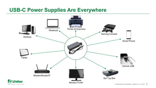
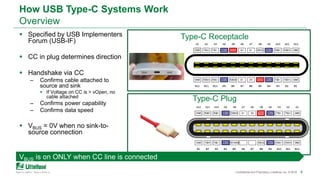
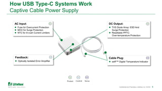
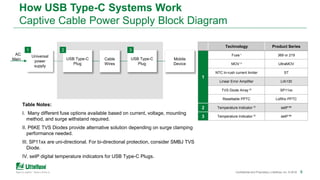
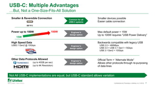
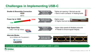
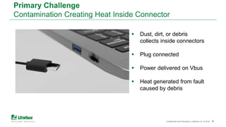
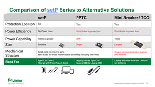
11
Preventing Over-temp
in USB Type-C Systems
Introducing the setP™ Digital
Temperature Indicator
222Confidential and Proprietary | Littelfuse, Inc. © 2018 2
USB-C Power Supplies Are Everywhere
Notebook
Monitor/TV/AV
Printer & Scanners
Set Top Box
Modem/Router/IT
Desktop
Gaming Console
Smart Phone
Tablet
Vehicle USB
33Confidential and Proprietary | Littelfuse, Inc. © 2018
USB-C Market Adoption Rate Estimates Increasing
5 Billion Devices by 2021
FIVE Billion Devices by 2021!
4Confidential and Proprietary | Littelfuse, Inc. © 2018 4
How USB Type-C Systems Work
Overview
 Specified by USB Implementers
Forum (USB-IF)
 CC in plug determines direction
 Handshake via CC
– Confirms cable attached to
source and sink
 If Voltage on CC is > vOpen, no
cable attached
– Confirms power capability
– Confirms data speed
 VBUS = 0V when no sink-to-
source connection
Type-C Receptacle
Type-C Plug
VBUS is on ONLY when CC line is connected
555Confidential and Proprietary | Littelfuse, Inc. © 2018 5
How USB Type-C Systems Work
Captive Cable Power Supply
Cable Plug:
 setP™ Digital Temperature Indicator
AC Input:
 Fuse for Overcurrent Protection
 MOV for Surge Protection
 NTC for In-rush Current Limiters
Feedback:
 Optically Isolated Error Amplifier
DC Output:
 TVS Diode Array: ESD And
Surge Protection
 Resettable PPTC:
Over-temperature Protection
666Confidential and Proprietary | Littelfuse, Inc. © 2018 6
How USB Type-C Systems Work
Captive Cable Power Supply Block Diagram
Technology Product Series
1
Fuse I 369 or 219
MOV II UltraMOV
NTC In-rush current limiter ST
Linear Error Amplifier LIA130
TVS Diode Array III SP11xx
Resettable PPTC LoRho PPTC
2 Temperature Indicator IV setP™
3 Temperature Indicator IV setP™
Universal
power
supply
1
USB Type-C
Plug
2
Table Notes:
I. Many different fuse options available based on current, voltage, mounting
method, and surge withstand required.
II. P6KE TVS Diodes provide alternative solution depending on surge clamping
performance needed.
III. SP11xx are uni-directional. For bi-directional protection, consider SMBJ TVS
Diode.
IV. setP digital temperature indicators for USB Type-C Plugs.
AC
Main USB Type-C
Plug
3
Cable
Wires
Mobile
Device
7Confidential and Proprietary | Littelfuse, Inc. © 2018 7
USB-C: Multiple Advantages
…But, Not a One-Size-Fits-All Solution
15W
100W
Engineer’s
design option
Engineer’s
design option
Engineer’s
design option
Common for all
USB-C systems
Not All USB-C implementations are equal, but USB-C standard allows variation
Smaller & Reversible Connection
Power up to 100W
High Speed Data
USB3.1 Gen2 @ 10Gbps
Other Data Protocols Allowed
(up to 40GB per sec)
(up to 4K Resolution)
Smaller devices possible
Easier cable connection
Max default power = 15W
Up to 100W requires “USB Power Delivery”
Backwards compatible with legacy USB
USB 2.0 = 480Mbps
USB 3.0 = USB 3.1 Gen1 = 5Gbps
USB 3.1 Gen2 = 10Gbps
Official Term = “Alternate Mode”
Allows other protocols through re-purposing
of data lines
8Confidential and Proprietary | Littelfuse, Inc. © 2018 8
Smaller & Reversible Connection Tighter pin spacing + Normal use dirt
+ bent or worn contacts  Heating faults
Power Up to 100W Higher power
 Higher thermal risk
High Speed Data Higher data speeds & Multiple protocols
USB3.1 Gen2 @ 10Gbps  Harder to ensure signal integrity
Alternate Modes
Up to 40Gbps with Thunderbolt 3
Challenges in Implementing USB-C
15W
100W
Uncontrolled over-heating could impact ‘compliant’ USB-C cables
Design can
improve
performance
Design can help
reduce ESD risk
Design can help
reduce thermal
risk
Normal use has
higher risk
thermal faults
9Confidential and Proprietary | Littelfuse, Inc. © 2018 9
Primary Challenge
Contamination Creating Heat Inside Connector
 Dust, dirt, or debris
collects inside connectors
 Plug connected
 Power delivered on Vbus
 Heat generated from fault
caused by debris
1010Confidential and Proprietary | Littelfuse, Inc. © 2018
Problem Condition: USB-C Plug
 Smaller Pin-to-Pin Spacing
– 23% less than micro-B
 Easier for contamination and damaged pins
to cause resistive fault
 USB-PD capable up to 100W
– Increasing likelihood of overheating
faults
– Micro-B typically only 18-25W
Smaller space with more power = more thermal risk
Power
Pin to Pin Spacing
Thermal Risk
1111Confidential and Proprietary | Littelfuse, Inc. © 2018
How setP™ Digital Temperature Indicator Works
In the plug, place on CC line as a sensing device.
Charger Cable Assembly Mobile Device
GND GND
 Charger is connected to the
AC power line and cable is
connected to the mobile device.
 Fault occurs (either at charger or mobile
device side), causing heat.
1) setP senses heat, then resistance (RsetP)
increase.
2) RsetP increase causes voltage on CC Line to
increase beyond specified value*.
VBUS
CC
VBUS
CCsetP
* vOpen value is defined by USB-IF as either 1.65V or 2.75V
POWER
setPsetP
1212Confidential and Proprietary | Littelfuse, Inc. © 2018
How setP Works
In the plug, place on CC line as a sensing device.
Charger Cable Assembly Mobile Device
GND GND
 Charger is connected to the
AC power line and cable is
connected to the mobile device.
 Fault occurs (either at charger or mobile
device side), causing heat.
1) setP senses heat, then resistance (RsetP)
increase.
2) RsetP increase causes voltage on CC Line to
increase beyond specified value*.
3) Systems assumes cable detached due to
voltage on CC being higher than specified
value*, thus VBUS power is turned off.
 System is protected
 To clear the fault: Disconnect Cable &
remove debris
VBUS
CC
VBUS
CCsetP
* vOpen value is defined by USB-IF as either 1.65V or 2.75V
setP
131313Confidential and Proprietary | Littelfuse, Inc. © 2018 13
setP Series Features & Benefits
Small size: 0805 (mils)
– 2.0mm x 1.2mm
Helps keep cable surface temperature safe for
customers
Independent of power
Protect 100W or higher systems
No disruption to USB PD
communication
Easy drop-in solution to existing designs
Sensitive switching temperature:
100ºC
20,000 Trip Events
Easy part selection
Features Benefits
Rigid physical structure
Reliably withstands modern assembly & molding
operations
14Confidential and Proprietary | Littelfuse, Inc. © 2018 14
Comparison of setP Series to Alternative Solutions
setP PPTC Mini-Breaker / TCO
Protection Location CC VBUS VBUS
Power Efficiency No Power Loss Contributes to power loss Contributes to power loss
Power Capability 100W or greater 60W 100W
Size Smallest Larger Largest
Mechanical
Structure
Solid-state, no moving parts
Well suited for most modern cable assembly including over-mold
Weaker mechanical structure leads to
poor reliability
Best For
Type-C to Type-C
Charger with Fixed Type-C Cable
Legacy USB to Type-C or
Legacy USB to Legacy USB
Laptop and other multi-cell Lithium-
ion batteries
15Confidential and Proprietary | Littelfuse, Inc. © 2018 15
Start Designing with setP
Ready to build setP into your USB-C system design? Our
guide can help.
Click below to access the downloadable guide.
Get the Guide
161616Confidential and Proprietary | Littelfuse, Inc. © 2018 16
Compliance and Standards for Power Supplies
 USB Type-C Cable and Connector Specification
 UL 1310 Standard for Class 2 Power Units
 UL 9990 Information and Communication Technology Power Cables
 IEC 60950-1 Information Technology Equipment Safety
 IEC 62368-1 Audio/video, information and communication technology equipment – Part 1: Safety requirements
 Mandatory efficiency requirements for supplies sold into various regions around the world
− Europe: Code of Conduct version 5
− USA: Department of Energy version VI
− China: National Development and Reform Commissions, “NDRC”
− Korea: Minimum Energy Performance Standards
− Israel: SI-4664.2
− India: Bureau of Energy Efficiency
 Electrostatic discharges to IEC 61000-4-2
 Fast Transient Burst Test to IEC 61000-4-4
 Fast Transient Surge Test to IEC 61000-4-5
171717Confidential and Proprietary | Littelfuse, Inc. © 2018 17
Over-temperature Protection For USB Type-C
Summary of setP Value Proposition
Reliable protection from World’s #1 circuit protection company
High power potential in small connector increases risk of thermal
failure.
 setP provides best combination of size, energy efficiency, and
indicating sensitivity.
 setP comes from PolySwitch family of products which have been
relied upon for over-temperature protection over 35 billion times.
18Confidential and Proprietary | Littelfuse, Inc. © 2018 18
Hear About Our Latest Consumer Electronics Products First
Click below to subscribe to our email newsletter.
You’ll receive helpful resources and product information
tailored to your interests.
Subscribe Now

Preventing Over-temperature in USB Type-C Systems: Introducing the Littelfuse setP Digital Temperature Indicator

  • 1.
    11 Preventing Over-temp in USBType-C Systems Introducing the setP™ Digital Temperature Indicator
  • 2.
    222Confidential and Proprietary| Littelfuse, Inc. © 2018 2 USB-C Power Supplies Are Everywhere Notebook Monitor/TV/AV Printer & Scanners Set Top Box Modem/Router/IT Desktop Gaming Console Smart Phone Tablet Vehicle USB
  • 3.
    33Confidential and Proprietary| Littelfuse, Inc. © 2018 USB-C Market Adoption Rate Estimates Increasing 5 Billion Devices by 2021 FIVE Billion Devices by 2021!
  • 4.
    4Confidential and Proprietary| Littelfuse, Inc. © 2018 4 How USB Type-C Systems Work Overview  Specified by USB Implementers Forum (USB-IF)  CC in plug determines direction  Handshake via CC – Confirms cable attached to source and sink  If Voltage on CC is > vOpen, no cable attached – Confirms power capability – Confirms data speed  VBUS = 0V when no sink-to- source connection Type-C Receptacle Type-C Plug VBUS is on ONLY when CC line is connected
  • 5.
    555Confidential and Proprietary| Littelfuse, Inc. © 2018 5 How USB Type-C Systems Work Captive Cable Power Supply Cable Plug:  setP™ Digital Temperature Indicator AC Input:  Fuse for Overcurrent Protection  MOV for Surge Protection  NTC for In-rush Current Limiters Feedback:  Optically Isolated Error Amplifier DC Output:  TVS Diode Array: ESD And Surge Protection  Resettable PPTC: Over-temperature Protection
  • 6.
    666Confidential and Proprietary| Littelfuse, Inc. © 2018 6 How USB Type-C Systems Work Captive Cable Power Supply Block Diagram Technology Product Series 1 Fuse I 369 or 219 MOV II UltraMOV NTC In-rush current limiter ST Linear Error Amplifier LIA130 TVS Diode Array III SP11xx Resettable PPTC LoRho PPTC 2 Temperature Indicator IV setP™ 3 Temperature Indicator IV setP™ Universal power supply 1 USB Type-C Plug 2 Table Notes: I. Many different fuse options available based on current, voltage, mounting method, and surge withstand required. II. P6KE TVS Diodes provide alternative solution depending on surge clamping performance needed. III. SP11xx are uni-directional. For bi-directional protection, consider SMBJ TVS Diode. IV. setP digital temperature indicators for USB Type-C Plugs. AC Main USB Type-C Plug 3 Cable Wires Mobile Device
  • 7.
    7Confidential and Proprietary| Littelfuse, Inc. © 2018 7 USB-C: Multiple Advantages …But, Not a One-Size-Fits-All Solution 15W 100W Engineer’s design option Engineer’s design option Engineer’s design option Common for all USB-C systems Not All USB-C implementations are equal, but USB-C standard allows variation Smaller & Reversible Connection Power up to 100W High Speed Data USB3.1 Gen2 @ 10Gbps Other Data Protocols Allowed (up to 40GB per sec) (up to 4K Resolution) Smaller devices possible Easier cable connection Max default power = 15W Up to 100W requires “USB Power Delivery” Backwards compatible with legacy USB USB 2.0 = 480Mbps USB 3.0 = USB 3.1 Gen1 = 5Gbps USB 3.1 Gen2 = 10Gbps Official Term = “Alternate Mode” Allows other protocols through re-purposing of data lines
  • 8.
    8Confidential and Proprietary| Littelfuse, Inc. © 2018 8 Smaller & Reversible Connection Tighter pin spacing + Normal use dirt + bent or worn contacts  Heating faults Power Up to 100W Higher power  Higher thermal risk High Speed Data Higher data speeds & Multiple protocols USB3.1 Gen2 @ 10Gbps  Harder to ensure signal integrity Alternate Modes Up to 40Gbps with Thunderbolt 3 Challenges in Implementing USB-C 15W 100W Uncontrolled over-heating could impact ‘compliant’ USB-C cables Design can improve performance Design can help reduce ESD risk Design can help reduce thermal risk Normal use has higher risk thermal faults
  • 9.
    9Confidential and Proprietary| Littelfuse, Inc. © 2018 9 Primary Challenge Contamination Creating Heat Inside Connector  Dust, dirt, or debris collects inside connectors  Plug connected  Power delivered on Vbus  Heat generated from fault caused by debris
  • 10.
    1010Confidential and Proprietary| Littelfuse, Inc. © 2018 Problem Condition: USB-C Plug  Smaller Pin-to-Pin Spacing – 23% less than micro-B  Easier for contamination and damaged pins to cause resistive fault  USB-PD capable up to 100W – Increasing likelihood of overheating faults – Micro-B typically only 18-25W Smaller space with more power = more thermal risk Power Pin to Pin Spacing Thermal Risk
  • 11.
    1111Confidential and Proprietary| Littelfuse, Inc. © 2018 How setP™ Digital Temperature Indicator Works In the plug, place on CC line as a sensing device. Charger Cable Assembly Mobile Device GND GND  Charger is connected to the AC power line and cable is connected to the mobile device.  Fault occurs (either at charger or mobile device side), causing heat. 1) setP senses heat, then resistance (RsetP) increase. 2) RsetP increase causes voltage on CC Line to increase beyond specified value*. VBUS CC VBUS CCsetP * vOpen value is defined by USB-IF as either 1.65V or 2.75V POWER setPsetP
  • 12.
    1212Confidential and Proprietary| Littelfuse, Inc. © 2018 How setP Works In the plug, place on CC line as a sensing device. Charger Cable Assembly Mobile Device GND GND  Charger is connected to the AC power line and cable is connected to the mobile device.  Fault occurs (either at charger or mobile device side), causing heat. 1) setP senses heat, then resistance (RsetP) increase. 2) RsetP increase causes voltage on CC Line to increase beyond specified value*. 3) Systems assumes cable detached due to voltage on CC being higher than specified value*, thus VBUS power is turned off.  System is protected  To clear the fault: Disconnect Cable & remove debris VBUS CC VBUS CCsetP * vOpen value is defined by USB-IF as either 1.65V or 2.75V setP
  • 13.
    131313Confidential and Proprietary| Littelfuse, Inc. © 2018 13 setP Series Features & Benefits Small size: 0805 (mils) – 2.0mm x 1.2mm Helps keep cable surface temperature safe for customers Independent of power Protect 100W or higher systems No disruption to USB PD communication Easy drop-in solution to existing designs Sensitive switching temperature: 100ºC 20,000 Trip Events Easy part selection Features Benefits Rigid physical structure Reliably withstands modern assembly & molding operations
  • 14.
    14Confidential and Proprietary| Littelfuse, Inc. © 2018 14 Comparison of setP Series to Alternative Solutions setP PPTC Mini-Breaker / TCO Protection Location CC VBUS VBUS Power Efficiency No Power Loss Contributes to power loss Contributes to power loss Power Capability 100W or greater 60W 100W Size Smallest Larger Largest Mechanical Structure Solid-state, no moving parts Well suited for most modern cable assembly including over-mold Weaker mechanical structure leads to poor reliability Best For Type-C to Type-C Charger with Fixed Type-C Cable Legacy USB to Type-C or Legacy USB to Legacy USB Laptop and other multi-cell Lithium- ion batteries
  • 15.
    15Confidential and Proprietary| Littelfuse, Inc. © 2018 15 Start Designing with setP Ready to build setP into your USB-C system design? Our guide can help. Click below to access the downloadable guide. Get the Guide
  • 16.
    161616Confidential and Proprietary| Littelfuse, Inc. © 2018 16 Compliance and Standards for Power Supplies  USB Type-C Cable and Connector Specification  UL 1310 Standard for Class 2 Power Units  UL 9990 Information and Communication Technology Power Cables  IEC 60950-1 Information Technology Equipment Safety  IEC 62368-1 Audio/video, information and communication technology equipment – Part 1: Safety requirements  Mandatory efficiency requirements for supplies sold into various regions around the world − Europe: Code of Conduct version 5 − USA: Department of Energy version VI − China: National Development and Reform Commissions, “NDRC” − Korea: Minimum Energy Performance Standards − Israel: SI-4664.2 − India: Bureau of Energy Efficiency  Electrostatic discharges to IEC 61000-4-2  Fast Transient Burst Test to IEC 61000-4-4  Fast Transient Surge Test to IEC 61000-4-5
  • 17.
    171717Confidential and Proprietary| Littelfuse, Inc. © 2018 17 Over-temperature Protection For USB Type-C Summary of setP Value Proposition Reliable protection from World’s #1 circuit protection company High power potential in small connector increases risk of thermal failure.  setP provides best combination of size, energy efficiency, and indicating sensitivity.  setP comes from PolySwitch family of products which have been relied upon for over-temperature protection over 35 billion times.
  • 18.
    18Confidential and Proprietary| Littelfuse, Inc. © 2018 18 Hear About Our Latest Consumer Electronics Products First Click below to subscribe to our email newsletter. You’ll receive helpful resources and product information tailored to your interests. Subscribe Now

Editor's Notes

  • #3 Laptops LED drivers Medical Rugged laptop Printer Scanner Phones Monitor Set top box Modem / Router