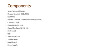
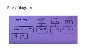
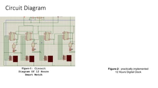
CHITTAGONG UNIVERSITY OF ENGINEEING AND TECHNOLOGY
Department of Biomedical Engineering
12 Hours Digital Clock Using
Seven Segment Display
Presented by
DIGITAL CLOCK
Table of Contents
• Objectives
• Component
• Circuit Diagram
• Methodology
• Application
• Limitation
• Conclusion
Objectives
• To Building a 12hour Smart Watch.
• To learn about the components.
• To learn about seven segment display system.
• Practically learned application of logic gates.
Introduction
• A digital clock is a type of clock that displays the time digitally.
• Digital clock opposed to an analogue clock.
• Hours, minute, seconds are indicated by digit.
• Digital clock represent by seven segment display.
Components
• Seven Segment Display
• Decade Counter( 4060 ,4026)
• IC( 7400 )
• Resistor (10kohm,330ohm,100kohm,330kohm )
• Capacitor :30pF
• Zener Diode:1N 4148
• Crystal Oscillator 32.768 kHz
• Push Switch
• LED
• Transistor BC 548
• Jumper Wires
• Bread Board
• Power Supply
Module Structure
Block Diagram
Circuit Diagram
Figure-1: Circuit
Diagram Of 12 Hours
Smart Watch
Figure-2: practically implemented
12 Hours Digital Clock
Methodology
7 segment display
Truth table of BCD to 7 segment display
Component Driscription
3 Input AND Gate
• It works as a reset button and clock pulse
generator.
• If e=f=g=1, then the output of the AND Gate is
1.As a result the IC 4026 resets and a clock
pulse is sent to the next IC 4026.
Crystal Oscillator
• For providing a stable clock signal .
Decade Counter
 To count clock pulses and return the output in
a form which can be displayed on a seven-
segment display.
 To display decimal digits (0-9).
Application
There are many uses for digital clocks
in daily life. It can be used, for instance, to
keep time in homes, offices, and classrooms.
Because they are more accurate than analog
clocks, digital clocks make it simpler for
everyone to keep track of the time.
Limitation
 This project does not run unless the source voltage is 9V.
 The total capacitance of the capacitors has to be 1.25 µF. Unless:
1.If the capacitance is less than 1.25 µF, the clock becomes faster.
2.If the capacitance is more than 1.25 µF, the clock becomes slower.
• Digital clocks is that they are more expensive than analog clocks.
• Don't last as long before needing replacement batteries.
Conclusion
The project was designed by using both the combinational and
sequential circuit with Crystal Oscillator to implement 12 hours
digital clock.
The circuit was initially designed using basic logic gates.
This project taught us about various types of counter and sequential
circuits. It also taught us how to work in groups.
THANK YOU

Presentation.pptx

  • 1.
    CHITTAGONG UNIVERSITY OFENGINEEING AND TECHNOLOGY Department of Biomedical Engineering 12 Hours Digital Clock Using Seven Segment Display Presented by
  • 2.
  • 3.
    Table of Contents •Objectives • Component • Circuit Diagram • Methodology • Application • Limitation • Conclusion
  • 4.
    Objectives • To Buildinga 12hour Smart Watch. • To learn about the components. • To learn about seven segment display system. • Practically learned application of logic gates.
  • 5.
    Introduction • A digitalclock is a type of clock that displays the time digitally. • Digital clock opposed to an analogue clock. • Hours, minute, seconds are indicated by digit. • Digital clock represent by seven segment display.
  • 6.
    Components • Seven SegmentDisplay • Decade Counter( 4060 ,4026) • IC( 7400 ) • Resistor (10kohm,330ohm,100kohm,330kohm ) • Capacitor :30pF • Zener Diode:1N 4148 • Crystal Oscillator 32.768 kHz • Push Switch • LED • Transistor BC 548 • Jumper Wires • Bread Board • Power Supply
  • 7.
  • 8.
  • 9.
    Circuit Diagram Figure-1: Circuit DiagramOf 12 Hours Smart Watch Figure-2: practically implemented 12 Hours Digital Clock
  • 10.
  • 11.
    7 segment display Truthtable of BCD to 7 segment display
  • 12.
    Component Driscription 3 InputAND Gate • It works as a reset button and clock pulse generator. • If e=f=g=1, then the output of the AND Gate is 1.As a result the IC 4026 resets and a clock pulse is sent to the next IC 4026. Crystal Oscillator • For providing a stable clock signal .
  • 13.
    Decade Counter  Tocount clock pulses and return the output in a form which can be displayed on a seven- segment display.  To display decimal digits (0-9).
  • 14.
    Application There are manyuses for digital clocks in daily life. It can be used, for instance, to keep time in homes, offices, and classrooms. Because they are more accurate than analog clocks, digital clocks make it simpler for everyone to keep track of the time.
  • 15.
    Limitation  This projectdoes not run unless the source voltage is 9V.  The total capacitance of the capacitors has to be 1.25 µF. Unless: 1.If the capacitance is less than 1.25 µF, the clock becomes faster. 2.If the capacitance is more than 1.25 µF, the clock becomes slower. • Digital clocks is that they are more expensive than analog clocks. • Don't last as long before needing replacement batteries.
  • 16.
    Conclusion The project wasdesigned by using both the combinational and sequential circuit with Crystal Oscillator to implement 12 hours digital clock. The circuit was initially designed using basic logic gates. This project taught us about various types of counter and sequential circuits. It also taught us how to work in groups.
  • 17.