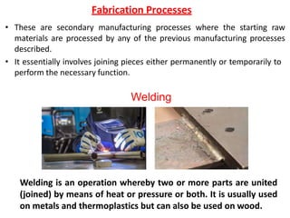
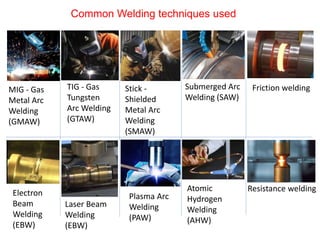
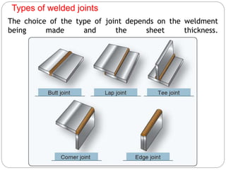
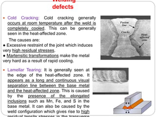
Unit 4 Part-2
Secondary Manufacturing Process:
Welding
Fabrication Processes
• These are secondary manufacturing processes where the starting raw
materials are processed by any of the previous manufacturing processes
described.
• It essentially involves joining pieces either permanently or temporarily to
perform the necessary function.
Welding
Welding is an operation whereby two or more parts are united
(joined) by means of heat or pressure or both. It is usually used
on metals and thermoplastics but can also be used on wood.
Classification of welding processes
1. Gas welding
2. Arc welding
3. Resistance welding
4. Solid-state welding
5. Thermo-chemical welding
6. Radiant energy welding
Gas welding:
- Oxy-acetylene welding
- Air acetylene welding
- Oxy-hydrogen welding
- Pressure gas welding
Arc welding:
- Carbon arc
- Flux cored arc
- TIG or GTAW
- Plasma arc
- Electro slag & electro gas
- Shielded metal arc
- Submerged arc
- MIG or GMAW
- Stud arc
Resistance welding:
- Spot
- Seam
- Projection
- Resistance butt
- Flash butt
- Percussion
- HF resistance
Solid state welding:
- Cold welding
- Explosive welding
- Friction welding
- Roll welding
- Diffusion welding
- Forge welding
- Hot-pressure welding
- Ultrasonic welding
Thermo-chemical:
- Thermit welding
- Atomic hydrogen welding
Radiant energy welding:
- Electron beam welding
- Laser beam welding
Allied process:
- Brazing
- Soldering
Common Welding techniques used
MIG - Gas
Metal Arc
Welding
(GMAW)
Electron
Beam
Welding
(EBW)
TIG - Gas
Tungsten
Arc Welding
(GTAW)
Stick -
Shielded
Metal Arc
Welding
(SMAW)
Submerged Arc
Welding (SAW)
Laser Beam
Welding
(EBW)
Plasma Arc
Welding
(PAW)
Atomic
Hydrogen
Welding
(AHW)
Friction welding
Resistance welding
Types of welded joints
The choice of the type of joint depends on the weldment
being made and the sheet thickness.
Welded joint terminology
Electric Arc welding
Electric Arc welding is a type of welding process using an electric arc to create heat
to melt and join metals.
A power supply (using either direct current (DC) or alternating current (AC))
generates an electric arc between a consumable or non-consumable electrode and
the base material.
An electric arc creates an intense heat
of around 6500°F which melts the
metal at the interface between two
workpieces.
The arc can be either manually or
mechanically guided along the line
of the interface of two materials,
while the electrode either simply
carry the current or conduct the
current and melt into the weld pool
at the same time to supply filler
metal to the joint.
Different Types of Arc Welding
Consumable Electrode Methods
Gas Metal Arc Welding (GMAW)
Shielded Metal Arc Welding (SMAW)
Flux Cored Arc Welding (FCAW)
Submerged Arc Welding (SAW)
Electro-Slag Welding (ESW)
Non-Consumable Electrode Methods
Gas Tungsten Arc Welding (GTAW)
Plasma Arc Welding (PAW)
Gas metal arc welding (GMAW)
Gas metal arc welding (GMAW) uses a continuous solid wire electrode which is
heated and fed into the weld pool from a welding gun.
The two base materials are melted together which causes them to join.
The welding gun also feeds an inert shielding gas alongside the wire electrode,
which helps protect the process from airborne contaminants.
Process feature of Gas metal arc welding (GMAW)
GMAW is a versatile technique suitable for both thin sheet and thick section
components.
An arc is struck between the end of a wire electrode and the workpiece, melting
both of them to form a weld pool.
The wire serves as both heat source (via the arc at the wire tip) and filler metal
for the joint. The wire is fed through a copper contact tube (contact tip) which
conducts welding current into the wire.
The weld pool is protected from the surrounding atmosphere by a shielding gas
fed through a nozzle surrounding the wire.
The wire is fed from a reel by a motor drive, and the welder moves the welding
torch along the joint line. Wires may be solid (simple drawn wires), or cored
(composites formed from a metal sheath with a powdered flux or metal filling).
The process offers high productivity, as the wire is continuously fed.
Gas Tungsten Arc Welding (GTAW) is an arc welding process that produces the weld
with a non-consumable tungsten electrode.
Gas Tungsten Arc Welding (GTAW)
The arc is formed between a pointed tungsten electrode and the workpiece in an
inert atmosphere of argon or helium. The small intense arc provided by the
pointed electrode is ideal for high quality and precision welding. When filler metal
is required, it must be added separately to the weldpool.
Gas welding
The gas welding is particularly suitable for joining metal sheets and plates having
thickness of 2 to 50 mm.
An additional metal called filler material is used for thickness more than 15 mm. This
filler metal is used in the form of welding rod.
The composition of filler rod is usually same as that of base metal. The filler metal is
used to fill up the cavity made during edge preparation.
A flux material is also used during welding to remove impurities and oxides present
on the metal surfaces to be joined.
Different combinations of gases are used to produce hot gas flame, e.g., Oxygen and
acetylene, oxygen and hydrogen, oxygen and propane, air and acetylene etc.
Gas Welding uses fuel gas (or liquid fuels such as gasoline) and oxygen to weld
materials.
Oxyacetylene gas welding set up
Schematic of Oxyacetylene gas welding torch and welding process
Process features of Oxyacetylene gas welding
Oxyacetylene welding relies on combustion of oxygen
and acetylene. When mixed together in correct
proportions within a hand-held torch or blowpipe, a
relatively hot flame is produced with a temperature
of about 3,200⁰C. The chemical action of the
oxyacetylene flame can be adjusted by changing the
ratio of the volume of oxygen to acetylene.
Three distinct flame settings are used: neutral, oxidising and carburising.
Welding is generally carried out using the neutral flame setting which has equal
quantities of oxygen and acetylene. The oxidising flame is obtained by increasing
just the oxygen flow rate while the carburising flame is achieved by increasing
acetylene flow in relation to oxygen flow.
Parts of the Flame
Parts of the flame are based on the temperature zones.
- Inner cone
- Inner reducing cone (in case of carburizing flame)
- Outer zone or envelope
The greatest amount of heat of produced just ahead of the inner cone.
Types of the Flame
Neutral flame:
-Neutral flame has two definite zones.
-Sharp brilliant cone extending a short distance from the torch tip.
-Outer envelope–bluish in colour.
-Inner cone develops heat and the outer envelope protects the
molten metal from oxidation.
-Neutral flame is used for welding steel, SS, Cast iron, Cu, Al, etc.
Types of the Flame
Carburizing flame/reducing flame:
-Percentage of acetylene is more.
-Sharply defined inner cone.
-Intermediate cone of whitish colour (feather).
-Bluish outer cone.
-The length of the intermediate cone is an indication of the
proportion of excess acetylene in flame.
- While welding steel, the presence of more acetylene tends to give
the weld a higher carbon content than the parent metal, resulting in
a hard and brittle weld.
Types of the Flame
Oxidizing flame:
-Percentage of oxygen is more.
-Have two zones.
-Small inner cone which has a purple colour.
-Outer cone/envelope.
-In oxidizing flame, the inner cone is not sharply defined.
-This flame is used for welding brass metal.
Types of the Flame
Resistance Welding
The welding processes covered so far are fusion welding processes where only
heat is applied in the joint.
In contrast, the resistance welding process is a fusion welding process where both
heat and pressure are applied to the joint but no filler metal or flux is added.
The heat necessary for the melting of the joint is obtained by the
heating effect of the electrical resistance of the joint and hence, the name
resistance welding.
Soldering
 Soldering is a method of joining similar or dissimilar metals by means of a filler
metal whose liquidus temperature is below 450°C.
 Though soldering obtains a good joint between the two plates, the strength of
the joint is limited by the strength of the filler metal used. Soldering is normally
used for obtaining a neat leak-proof joint or a low-resistance electrical joint. The
soldered joints are not suitable for high-temperature service because of the low
melting temperatures of the filler metals used.
Soldering
 Brazing is the coalescence of a joint with the help of a filler metal whose liquidus
temperature is above 450°C and is below the solidus temperature of the base
metal.
 The filler metal is drawn into the joint by means of capillary action (entering fluid
into tightly fitted surfaces). Dissimilar metals such as stainless steel to cast iron
can be joined by brazing.
 Except for aluminium and magnesium, brazing can join almost all metals.
Because of the lower temperatures used, there is less distortion in brazed joints.
Brazing
Brazing
 Undercut: This appears like a small notch in
the weld interface. This is generally attributed
to the improper welding technique or
excessive welding current. This is mainly
caused by the incorrect manipulation of the
electrode while depositing the bead,
particularly, in horizontal and vertical welding.
 Incomplete Fusion: This will be seen as a
discontinuity in the weld zone. The main
causes for this defect are improper
penetration of the joint, wrong design of the
joint, or incorrect welding technique including
the wrong choice of the welding parameters.
The main parameter that controls is the
welding current, if it is lower than required, it
would not sufficiently heat all the faces of the
joint to promote proper fusion. Also, the
improper cleaning of the joint hinders the
fusion of the metal in the joint.
Welding
defects
 Porosity: Porosity in welding is caused by the
presence of gases that get entrapped during the
solidification process. The main gases that cause
porosity are Hydrogen, Oxygen, and Nitrogen.
 Slag Inclusion: Slag is formed by the reaction with the
fluxes and is generally lighter. In view of its low
density, it will float on top of the weld pool and would
be chipped off after solidification.
 Hot Cracking: Generally occurs at high temperatures
and the size can be very small to visible. The crack is,
in most parts, intergranular and its magnitude depends
upon the strains involved in solidification. It occurs
when the available supply of liquid weld metal is
insufficient to fill the spaces between solidifying weld
metal, which is opened by shrinkage strains. Liquid
Welding
defects
 Cold Cracking: Cold cracking generally
occurs at room temperature after the weld is
completely cooled. This can be generally
seen in the heat-affected zone.
The causes are:
● Excessive restraint of the joint which induces
very high residual stresses.
● Martensitic transformations make the metal
very hard as a result of rapid cooling.
Welding
defects
 Lamellar Tearing: It is generally seen at
the edge of the heat-affected zone. It
appears as a long and continuous visual
separation line between the base metal
and the heat-affected zone. This is caused
by the presence of the elongated
inclusions such as Mn, Fe, and S in the
base metal. It can also be caused by the
weld configuration which gives rise to high
References
• Manufacturing Technology Volume I (Foundry, Forming
and Welding) by P N Rao
• https://www.youtube.com/watch?v=43KqYUtwQQc
• https://www.youtube.com/watch?v=Rq_Vuye4HL0
• Texts and Figures available on the Web, Books, and
Study materials

Presentation4 BME unit-4 part-2.pptxmechanical

  • 1.
    Unit 4 Part-2 SecondaryManufacturing Process: Welding
  • 2.
    Fabrication Processes • Theseare secondary manufacturing processes where the starting raw materials are processed by any of the previous manufacturing processes described. • It essentially involves joining pieces either permanently or temporarily to perform the necessary function. Welding Welding is an operation whereby two or more parts are united (joined) by means of heat or pressure or both. It is usually used on metals and thermoplastics but can also be used on wood.
  • 3.
    Classification of weldingprocesses 1. Gas welding 2. Arc welding 3. Resistance welding 4. Solid-state welding 5. Thermo-chemical welding 6. Radiant energy welding Gas welding: - Oxy-acetylene welding - Air acetylene welding - Oxy-hydrogen welding - Pressure gas welding Arc welding: - Carbon arc - Flux cored arc - TIG or GTAW - Plasma arc - Electro slag & electro gas - Shielded metal arc - Submerged arc - MIG or GMAW - Stud arc Resistance welding: - Spot - Seam - Projection - Resistance butt - Flash butt - Percussion - HF resistance
  • 4.
    Solid state welding: -Cold welding - Explosive welding - Friction welding - Roll welding - Diffusion welding - Forge welding - Hot-pressure welding - Ultrasonic welding Thermo-chemical: - Thermit welding - Atomic hydrogen welding Radiant energy welding: - Electron beam welding - Laser beam welding Allied process: - Brazing - Soldering
  • 5.
    Common Welding techniquesused MIG - Gas Metal Arc Welding (GMAW) Electron Beam Welding (EBW) TIG - Gas Tungsten Arc Welding (GTAW) Stick - Shielded Metal Arc Welding (SMAW) Submerged Arc Welding (SAW) Laser Beam Welding (EBW) Plasma Arc Welding (PAW) Atomic Hydrogen Welding (AHW) Friction welding Resistance welding
  • 6.
    Types of weldedjoints The choice of the type of joint depends on the weldment being made and the sheet thickness.
  • 7.
  • 8.
    Electric Arc welding ElectricArc welding is a type of welding process using an electric arc to create heat to melt and join metals. A power supply (using either direct current (DC) or alternating current (AC)) generates an electric arc between a consumable or non-consumable electrode and the base material. An electric arc creates an intense heat of around 6500°F which melts the metal at the interface between two workpieces. The arc can be either manually or mechanically guided along the line of the interface of two materials, while the electrode either simply carry the current or conduct the current and melt into the weld pool at the same time to supply filler metal to the joint.
  • 9.
    Different Types ofArc Welding Consumable Electrode Methods Gas Metal Arc Welding (GMAW) Shielded Metal Arc Welding (SMAW) Flux Cored Arc Welding (FCAW) Submerged Arc Welding (SAW) Electro-Slag Welding (ESW) Non-Consumable Electrode Methods Gas Tungsten Arc Welding (GTAW) Plasma Arc Welding (PAW)
  • 10.
    Gas metal arcwelding (GMAW) Gas metal arc welding (GMAW) uses a continuous solid wire electrode which is heated and fed into the weld pool from a welding gun. The two base materials are melted together which causes them to join. The welding gun also feeds an inert shielding gas alongside the wire electrode, which helps protect the process from airborne contaminants.
  • 11.
    Process feature ofGas metal arc welding (GMAW) GMAW is a versatile technique suitable for both thin sheet and thick section components. An arc is struck between the end of a wire electrode and the workpiece, melting both of them to form a weld pool. The wire serves as both heat source (via the arc at the wire tip) and filler metal for the joint. The wire is fed through a copper contact tube (contact tip) which conducts welding current into the wire. The weld pool is protected from the surrounding atmosphere by a shielding gas fed through a nozzle surrounding the wire. The wire is fed from a reel by a motor drive, and the welder moves the welding torch along the joint line. Wires may be solid (simple drawn wires), or cored (composites formed from a metal sheath with a powdered flux or metal filling). The process offers high productivity, as the wire is continuously fed.
  • 12.
    Gas Tungsten ArcWelding (GTAW) is an arc welding process that produces the weld with a non-consumable tungsten electrode. Gas Tungsten Arc Welding (GTAW) The arc is formed between a pointed tungsten electrode and the workpiece in an inert atmosphere of argon or helium. The small intense arc provided by the pointed electrode is ideal for high quality and precision welding. When filler metal is required, it must be added separately to the weldpool.
  • 13.
    Gas welding The gaswelding is particularly suitable for joining metal sheets and plates having thickness of 2 to 50 mm. An additional metal called filler material is used for thickness more than 15 mm. This filler metal is used in the form of welding rod. The composition of filler rod is usually same as that of base metal. The filler metal is used to fill up the cavity made during edge preparation. A flux material is also used during welding to remove impurities and oxides present on the metal surfaces to be joined. Different combinations of gases are used to produce hot gas flame, e.g., Oxygen and acetylene, oxygen and hydrogen, oxygen and propane, air and acetylene etc. Gas Welding uses fuel gas (or liquid fuels such as gasoline) and oxygen to weld materials.
  • 14.
  • 15.
    Schematic of Oxyacetylenegas welding torch and welding process
  • 16.
    Process features ofOxyacetylene gas welding Oxyacetylene welding relies on combustion of oxygen and acetylene. When mixed together in correct proportions within a hand-held torch or blowpipe, a relatively hot flame is produced with a temperature of about 3,200⁰C. The chemical action of the oxyacetylene flame can be adjusted by changing the ratio of the volume of oxygen to acetylene. Three distinct flame settings are used: neutral, oxidising and carburising. Welding is generally carried out using the neutral flame setting which has equal quantities of oxygen and acetylene. The oxidising flame is obtained by increasing just the oxygen flow rate while the carburising flame is achieved by increasing acetylene flow in relation to oxygen flow.
  • 17.
    Parts of theFlame Parts of the flame are based on the temperature zones. - Inner cone - Inner reducing cone (in case of carburizing flame) - Outer zone or envelope The greatest amount of heat of produced just ahead of the inner cone.
  • 18.
  • 19.
    Neutral flame: -Neutral flamehas two definite zones. -Sharp brilliant cone extending a short distance from the torch tip. -Outer envelope–bluish in colour. -Inner cone develops heat and the outer envelope protects the molten metal from oxidation. -Neutral flame is used for welding steel, SS, Cast iron, Cu, Al, etc. Types of the Flame
  • 20.
    Carburizing flame/reducing flame: -Percentageof acetylene is more. -Sharply defined inner cone. -Intermediate cone of whitish colour (feather). -Bluish outer cone. -The length of the intermediate cone is an indication of the proportion of excess acetylene in flame. - While welding steel, the presence of more acetylene tends to give the weld a higher carbon content than the parent metal, resulting in a hard and brittle weld. Types of the Flame
  • 21.
    Oxidizing flame: -Percentage ofoxygen is more. -Have two zones. -Small inner cone which has a purple colour. -Outer cone/envelope. -In oxidizing flame, the inner cone is not sharply defined. -This flame is used for welding brass metal. Types of the Flame
  • 22.
    Resistance Welding The weldingprocesses covered so far are fusion welding processes where only heat is applied in the joint. In contrast, the resistance welding process is a fusion welding process where both heat and pressure are applied to the joint but no filler metal or flux is added. The heat necessary for the melting of the joint is obtained by the heating effect of the electrical resistance of the joint and hence, the name resistance welding.
  • 23.
    Soldering  Soldering isa method of joining similar or dissimilar metals by means of a filler metal whose liquidus temperature is below 450°C.  Though soldering obtains a good joint between the two plates, the strength of the joint is limited by the strength of the filler metal used. Soldering is normally used for obtaining a neat leak-proof joint or a low-resistance electrical joint. The soldered joints are not suitable for high-temperature service because of the low melting temperatures of the filler metals used.
  • 24.
  • 25.
     Brazing isthe coalescence of a joint with the help of a filler metal whose liquidus temperature is above 450°C and is below the solidus temperature of the base metal.  The filler metal is drawn into the joint by means of capillary action (entering fluid into tightly fitted surfaces). Dissimilar metals such as stainless steel to cast iron can be joined by brazing.  Except for aluminium and magnesium, brazing can join almost all metals. Because of the lower temperatures used, there is less distortion in brazed joints. Brazing
  • 26.
  • 27.
     Undercut: Thisappears like a small notch in the weld interface. This is generally attributed to the improper welding technique or excessive welding current. This is mainly caused by the incorrect manipulation of the electrode while depositing the bead, particularly, in horizontal and vertical welding.  Incomplete Fusion: This will be seen as a discontinuity in the weld zone. The main causes for this defect are improper penetration of the joint, wrong design of the joint, or incorrect welding technique including the wrong choice of the welding parameters. The main parameter that controls is the welding current, if it is lower than required, it would not sufficiently heat all the faces of the joint to promote proper fusion. Also, the improper cleaning of the joint hinders the fusion of the metal in the joint. Welding defects
  • 28.
     Porosity: Porosityin welding is caused by the presence of gases that get entrapped during the solidification process. The main gases that cause porosity are Hydrogen, Oxygen, and Nitrogen.  Slag Inclusion: Slag is formed by the reaction with the fluxes and is generally lighter. In view of its low density, it will float on top of the weld pool and would be chipped off after solidification.  Hot Cracking: Generally occurs at high temperatures and the size can be very small to visible. The crack is, in most parts, intergranular and its magnitude depends upon the strains involved in solidification. It occurs when the available supply of liquid weld metal is insufficient to fill the spaces between solidifying weld metal, which is opened by shrinkage strains. Liquid Welding defects
  • 29.
     Cold Cracking:Cold cracking generally occurs at room temperature after the weld is completely cooled. This can be generally seen in the heat-affected zone. The causes are: ● Excessive restraint of the joint which induces very high residual stresses. ● Martensitic transformations make the metal very hard as a result of rapid cooling. Welding defects  Lamellar Tearing: It is generally seen at the edge of the heat-affected zone. It appears as a long and continuous visual separation line between the base metal and the heat-affected zone. This is caused by the presence of the elongated inclusions such as Mn, Fe, and S in the base metal. It can also be caused by the weld configuration which gives rise to high
  • 30.
    References • Manufacturing TechnologyVolume I (Foundry, Forming and Welding) by P N Rao • https://www.youtube.com/watch?v=43KqYUtwQQc • https://www.youtube.com/watch?v=Rq_Vuye4HL0 • Texts and Figures available on the Web, Books, and Study materials