Purpose of digitalgovernor
• A digital governor is a control system used primarily in
hydropower turbines to:
• Maintain turbine speed at a desired set point despite load
variation
• Regulate power output to match grid demand
• Ensure system stability by responding rapidly to disturbances
• Optimize turbine efficiency by precise control of the wicket
gates or valves
• Reduce mechanical wear maintenance by replacing
mechanical linkages with electronic controls
• Enable remote monitoring and diagnosis via digital
communication interfaces
3.
Components of digitalgovernor
• Sensors
• Measure turbine speed ,load and other crtical parameters
• Often include speed sensors (tachometers) pressure sensors,and flow meters
• Controller unit (digital processor
• A microprocessor or PLC that excute the control algorithms
• Converts sensor inputs in to control signals for actuters
• Often programable for different operating modes
• Actaters /servomechanisms
• Hydraulic or electronic actuaters that adjust the position of the turbine gates /valves
• Receive controlsignal from the digital controller
• Human machine interface/HMI
• Display system status ,alrm,and allow s operator input
• Used for configrartion ,monitoring and manual overide
• Communication interfaces
• Connect the governor to plant control system like SCADA or DCS
• Enables dta exchange for monitoring and remote control
• Power supply
• Provide eelectrical power to sensors ccontrollrs and actuaters
4.
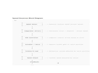
Operation of digitalgovernor
• The sensor measure the actual turbine speedand load
• The controllr compares the measured speed with the desired
speed setpoint
• Based on this error , the controller compares the required
adjustment using control algorithm (PID)
• The controller send signal to the actuator , which adjusts the
wickate gate or valve position
• This ajustment changes the water flow , which affects turbine
speed and power output
• The system continoisly monitors and adjusts to maintaine
stable operation under varieng load condition
5.
Control mechanism
• Speedcontroller mode : maintain constant
turbine speed regardless of the load change
• Load contrl mode: regulate power output by
controlling turbine speed within limites
• Valve position control : direct control of wickate
gate to manage flow precisely
• Droop control : implement proportional speed
drop with increasing load to share load between
multiple turbines
6.
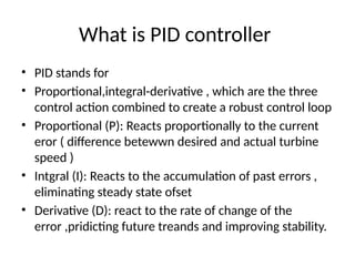
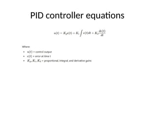
What is PIDcontroller
• PID stands for
• Proportional,integral-derivative , which are the three
control action combined to create a robust control loop
• Proportional (P): Reacts proportionally to the current
eror ( difference betewwn desired and actual turbine
speed )
• Intgral (I): Reacts to the accumulation of past errors ,
eliminating steady state ofset
• Derivative (D): react to the rate of change of the
error ,pridicting future treands and improving stability.
7.
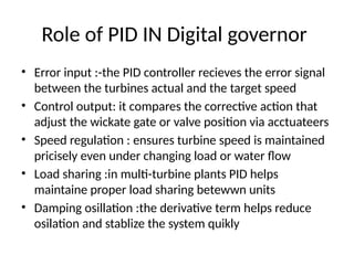
Role of PIDIN Digital governor
• Error input :-the PID controller recieves the error signal
between the turbines actual and the target speed
• Control output: it compares the corrective action that
adjust the wickate gate or valve position via acctuateers
• Speed regulation : ensures turbine speed is maintained
pricisely even under changing load or water flow
• Load sharing :in multi-turbine plants PID helps
maintaine proper load sharing betewwn units
• Damping osillation :the derivative term helps reduce
osilation and stablize the system quikly
8.
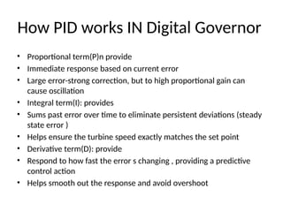
How PID worksIN Digital Governor
• Proportional term(P)n provide
• Immediate response based on current error
• Large error-strong correction, but to high proportional gain can
cause oscillation
• Integral term(I): provides
• Sums past error over time to eliminate persistent deviations (steady
state error )
• Helps ensure the turbine speed exactly matches the set point
• Derivative term(D): provide
• Respond to how fast the error s changing , providing a predictive
control action
• Helps smooth out the response and avoid overshoot
Benefits of usingPID digital governor
• Precise control
• Adaptability
• Stability
• Improved efficiency
12.
• The PIDtype governor typically receives two types of input
signals:
• Speed Error Signal (Primary Input):
– This is the difference between the reference speed (setpoint) and
the actual turbine speed measured by sensors.
• It represents how much the turbine speed deviates from the
desired value
• Load or Power Demand Signal (Secondary Input):
– This input reflects the desired power output or load demand from
the grid or control system.
– It helps adjust the governor's action to match changing load
requirements.
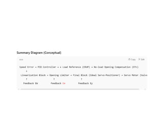
13.
Detailed Control Flowin a PID Type Digital Governor
• PID Controller Output:
– The PID controller processes the speed error signal and generates a preliminary control
output.
• Addition of Load Reference Signal (ERdP):
– The load reference signal is added downstream of the PID block.
– This input is active only after synchronization of the generator with the grid.
– It adjusts the turbine opening setpoint to meet the power demand while maintaining stable
operation.
• No-load Opening Compensation (EYv):
– After the node where PID output and load reference are combined, a block compensates for
no-load valve/gate opening.
– This compensation becomes active only after synchronization, ensuring proper valve position
even when there is no load.
– Linearization Block: Compensates for the nonlinear relationship between valve/gate opening
and power output.
– Ensures that valve positions correspond linearly to power changes, improving control accuracy.
14.
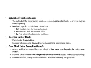
• Saturation FeedbackLoops:
– The output of the linearization block goes through saturation limits to prevent over or
under-opening.
– Feedback signals control these saturations:
• EW: Feedback from the linearization block.
• Em: Feedback from the limitation block.
• Ey: Final setpoint feedback to the positioner.
• Opening Limiter Block:
– Placed after linearization.
– Ensures valve opening stays within mechanical and operational limits.
• Final Block (Ideal Servo-Positioner):
– Acts as an ideal servo-positioner sending the final valve opening setpoint to the servo
motors.
– Includes calibration of operating times for servo-motors (speed and response tuning).
– Ensures smooth, timely valve movements as commanded by the governor.